Zedyone_kenobi
Free Member
-
Joined
-
Last visited
-
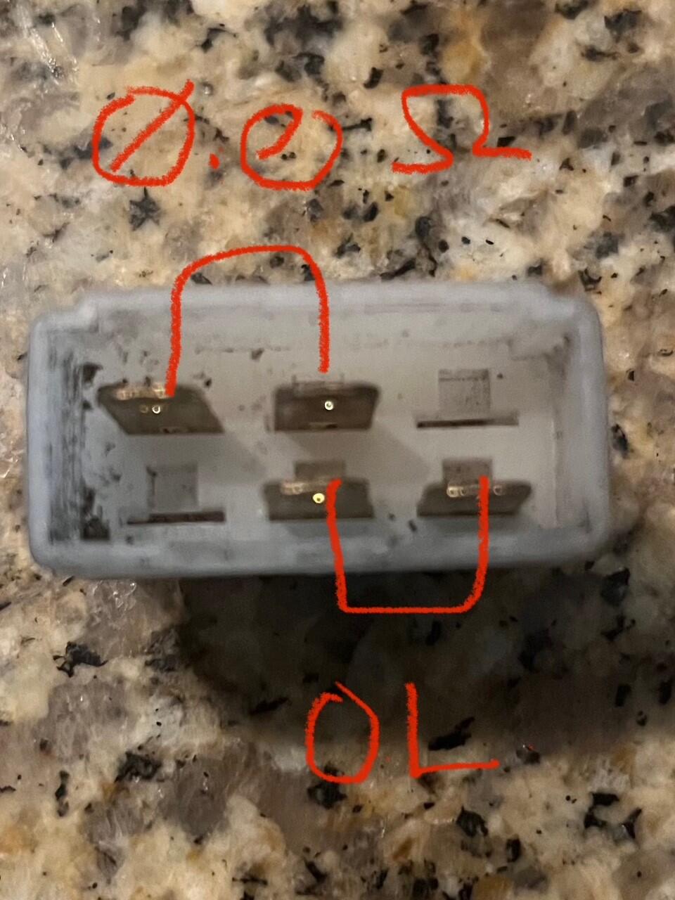
Update: My new alternator came in and when I tested the voltage regulator cap the leads that go to the diode read OL in one direction and when I switched the leads it read 0.597 V. That is what a diode should do. Low and behold the alternator is now outputting voltage. :) Problem solved. Now I have a spare alternator :)
-
-
-
So, while the failure seems possibly diagnosed, lets talk about why. What makes the alternator stop charging if that diode burns out. I have been looking a LOT at a 72 wiring diagram (I do not have a nice color 71 Z wiring diagram). I am trying to find something that looks like a feedback loop with a sense input, internal regulation and finally, output happens. I assumed the white wire with the red stripe coming out of the back of the alternator was the output voltage back to the fusebox and battery respectively. Is the T connector used in the feedback loop which tells the alternator to 'activate'
-
I already have another MSA alternator kit coming from MSA as we speak. It will be here in a few days. When I was just SURE it was the alternator I ordered one. But now it may look like I have a spare. It will come with the bypass clip for the Voltage regulator and I will swap it out then. If I had a spare diode laying around I could just solder up one with clips, but I am pretty sure I do not have one.
-
Okay, I went into the electrical lab at work and borrowed a Fluke. with the Multimeter on Ohms, with the leads going red to black (left to right) on the two pins with the diode the Resistance is 23M Ohms with the leads going black to red (left to right) on the two pins with the diode the Resistance is 1 M Ohms I then switched the Multimeter to Diode Tester. Red to black or black to red the Multimeter read OL.
-
-
-
-
Now I have no idea what the test read, as it only comes back with a big green check. No voltage out put was displayed. According to the 72 Z wiring diagram the red/white wire runs back to the fusebox, so that seems like it should be supplying the car with power after the car starts. My problem is that the wiring diagram shows the voltage regulator and I am running an internally regulated alternator. So I have to figure our which wire it is that should be charging my battery and which is supplying the car with power (me thinks red'white)
-
The alternator tested a big green check at the parts store. However, I tried to test to find any out put from the T connector while the alternator was running well I got nothing, but it would see that it fried my volt meter LOL LOL. I am sure I should have measured the red/white wire from the back of the alternator instead. But now I have to get a fuse for my voltmeter or a brand new voltmeter... which would not be horrible.
-
-
-
-
I pulled the alternator this morning (wearing my osha white safety socks - those who have followed my Z build will understand) and plan on taking it to get tested this afternoon. None of my connections were lose or corroded. No matter what I do the amperage never changes or moves with revs and the battery will NOT read more than 12.3 volts.