ea6driver
Community Member
-
Joined
-
Last visited
Everything posted by ea6driver
-
That's a good point. During the restoration process i did completely disassemble the the entire hand brake linkage. I guess I could have reassembled the linkage in a way that is putting tension on the cable, causing it to be so tight at the ends. I'll look at that tomorrow. Fortunately I haven't re installed the driveshaft yet so it should still be easy to access.
-
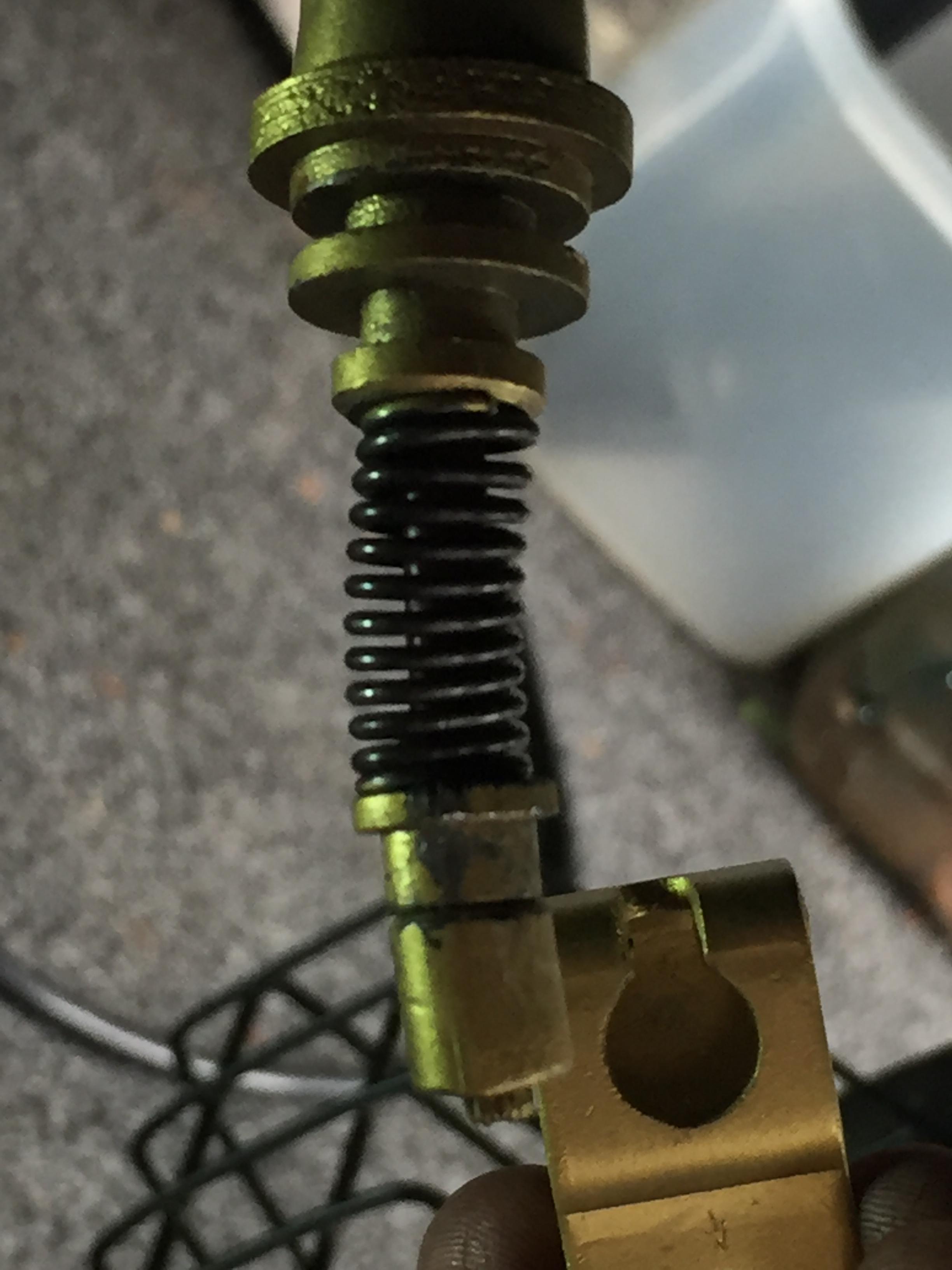
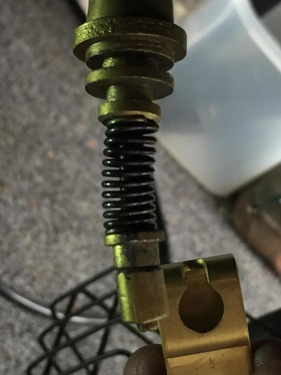
The hand brake handle/lever is down. The spring in the photo holds pressure (tension) on the end of the cable. The spring needs to be compressed to allow a gap for the bracket to fit in the area where the black line is in the photo. It's a stiff spring. As usual, taking it apart was much easier than putting it back together.
-
For the life of me ,I can't figure an easy way to re attach this handbrake hardware back onto the end of the cable. The spring tension is too much to compress with my hands. I'm thinking i might need a special tool to compress the spring enough to install the end piece... I'm looking for some advice.
-
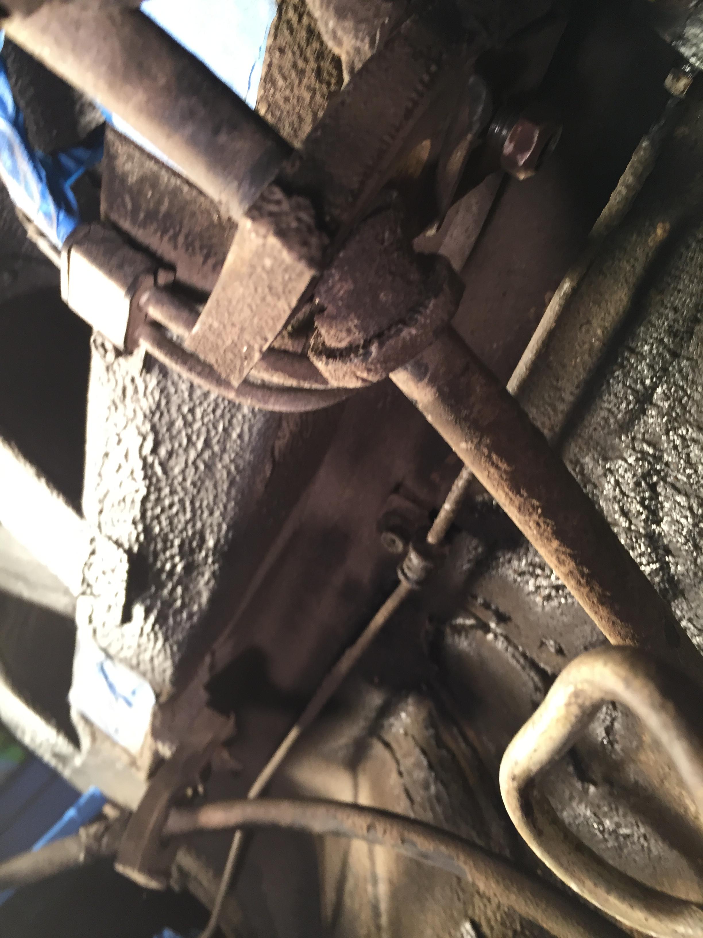
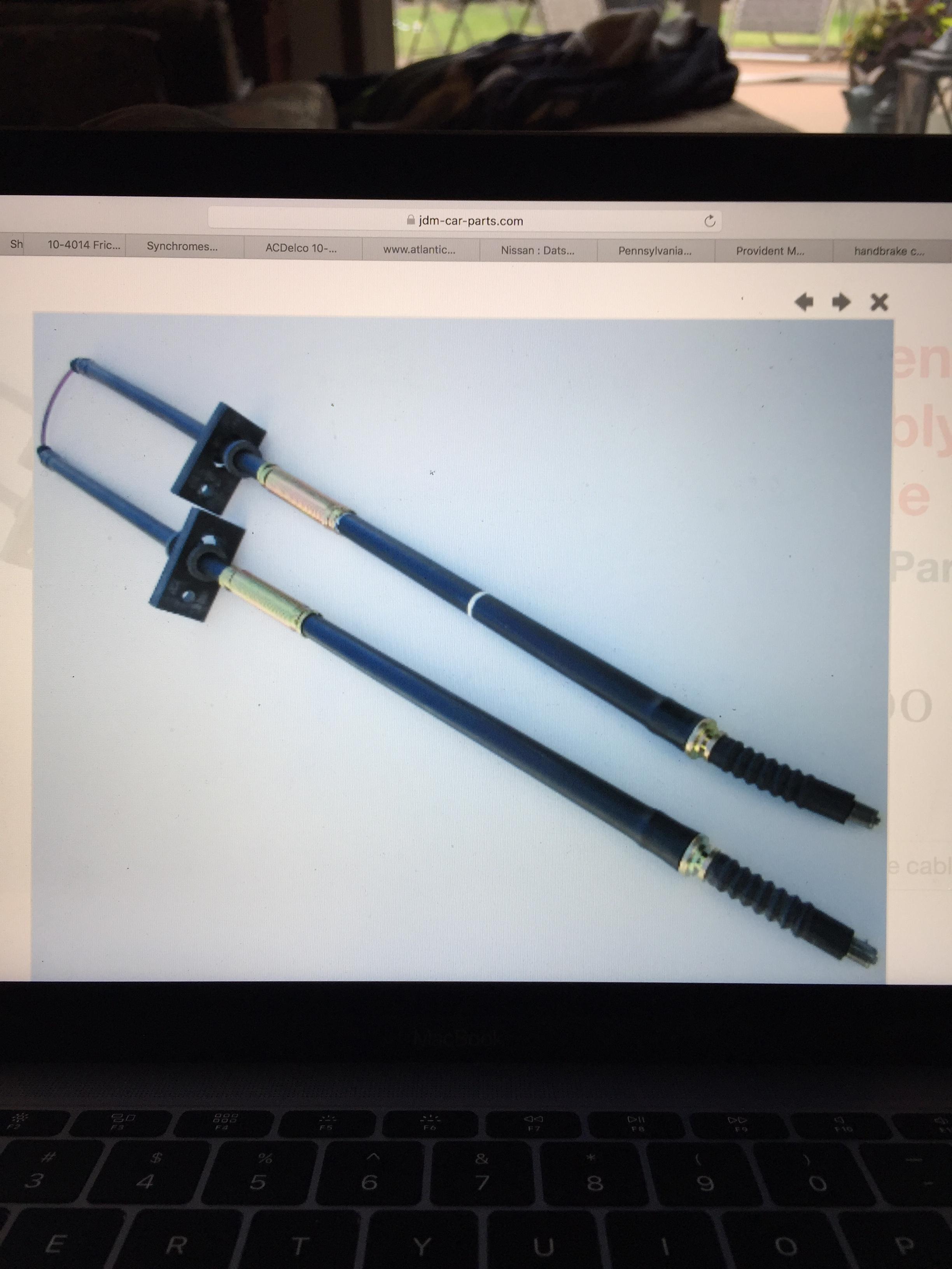
Thanks for that idea. Just to be clear, the rubber part I'm trying to replace is not the rectangular piece. It's the cylindrical piece that runs through the hole in the rectangular piece. This piece is only a couple inches long and slides over the actual handbrake cable. I'm thinking it's there to prevent the cable from sliding fore/aft in the rectangular hanger hole.
-
I'm looking to replace the original rubber "grommets" that encircled the handbrake cable where the handbrake cable runs through the rubber "hangers". I've attached a couple of photos to help show the rubber part I'm looking for. Anybody have any good ideas on a replacement part for this?


-
Thanks so much gentlemen...I do have the white/19 tooth speedo gear (had not thought about needing to install that with the OE tranny/3.90 diff combo). Tire/wheel combo is aftermarket, but same overall diameter as OE. Glad to find out that the Z will at least be drivable until I can get it back up on the jack stands in a few months. I appreciate all the comments.
-
I do have the correct (white) speedo gear to install in the replacement ZX 5 speed tranny, but the original gear is still in the OE tranny. Are you saying to go ahead and swap in the white gear in the OE tranny so the speedometer will be accurate?
-
78 280Z. Factory 4 speed. Car has been on jack stands in my garage for the last year while I've been restoring the underside. Pretty much have finished up the rear end, but my wife really wants me to get it out of the garage for a while this summer before I can finish up the front end. The restoration plan includes swapping out the OE 3.545 diff/4 speed tranny with a 3.90 diff/5 speed tranny from an 83 ZX. I've already installed the 3.90 diff. Would really like to delay installing the replacement tranny for a few months. My question is will the car be drivable with the 3.90 diff and the OE 4 speed tranny? I realize this combo won't be optimum, but by "drivable" I simply mean acceptable for a short term until I can get it back up on the jack stands after summer. I'd only be driving the car easy and on nice days....60 mph max. Thanks in advance for your advice.
-
Success...a "rat" file, some light lube and about 30 minutes of work and now the spindle pin passes right through by hand. And I think it was a combination of left over corrosion and at least a couple small burrs because a close inspection of the spindle pin after initially tapping it through with a rubber hammer did reveal a couple light scorch marks along its horizontal axis. But I couldn't see anything visually when looking through the hole with a light. Anyway...all is good now with this problem. On to the next...and thanks for all the good advice!
-
thanks zed. all good advice. i realize that "tight" is good...at least to a degree. right now i'm concerned that the fit is so tight that, once the holes in the control arm "ears" are aligned with the strut hole and the pin is pushed into place that it would be extremely difficult to rotate the pin any at all if necessary to align the notch in the spindle pin with the lock pin. Especially since, at that point, the only part of the spindle pin available to work with is the threaded ends. I'm off to the garage to pull out the rat file and some sandpaper.
-
The spindle pins are new. And they do seem to slide in fairly easily on both ends of the strut holes. Only after they've slid in a couple inches does the going get tough. So perhaps your idea about the area closer to the lock pin being a little deformed is in fact the problem. I'll try sanding/filing down around that area today to see if I can get things to fit better. Thanks!
-
Thanks for the tip...I'll do some more sanding on it tomorrow...another fun filled Saturday in the garage!
-
I didn't mean to give the impression that the old spindle pins came out easily. To the contrary. I had to use a sawzall to cut each pin into 3 pieces. Then I had to take the lower control arms and strut assemblies down to NAPA to have them press them out. They said getting the pin pieces out with their press was very difficult. I agree though...precision fit...no wobble. Right now, I'm not even close to the wobble stage. It's tight...very tight.
-
This diagram from the FSM makes it look like it should be fairly easy!

-
So tonight's' job involved installing new spindle pins into the rear strut assemblies. The question I have is...how tight/loose is an acceptable fit for the spindle pin in the strut housing hole? I tried reaming/cleaning out the inside of the hole passage by wrapping some sand paper around a dowel rod and passing it through the hole a few minutes. Then I greased up the pin real good. I can get the pin to pass through the hole, but only by tapping it with a hammer. It's so tight that the only way I can pull it out is by clamping down on the pin with vice grips and working it back and forth real good. I guess I'm really thinking I need to ream out the hole a little more and was hoping for some ideas on the best/easiest way to do that.

-
I had read elsewhere on the forum that others had difficulty reassembling the lower control arm and strut because of the very tight fit once the new PU bushings were in place. Some simply sanded down the "flanges" of the bushings while others discussed techniques for spreading the control arm mounting points. We'll see what happens once I see just how tight it is. As for the "wave washers" on the mustache bar, they are new OEM washers. They've been laying in a box in my garage for probably over a decade. I'm reusing the original bushing inside the mustache bar. It looked OK as far as I could see. I"m sure it isn't as good as new, but with all the complaints I'd read about PU bushings transmitting gear noise I just didn't want to take the chance with that.
-
Sorry about that...here's photos of the diagrams we've been talking about from the 78 FSM: The first photo is of page RA-10, diagram #RA276. It incorrectly shows the mustache bar installed on the 78Z with the mounting "cylinders" aft of the mustache bar itself (I've highlighted the actual mustache bar for clarity). It also incorrectly shows the bar installed forward of the link mounting brace. Post #6 above shows a photo the correct installation in a 78Z. The second photo is of page RA-11, diagram #RA278. While less obvious, it still shows the mustache bar incorrectly installed forward of the link mounting brace. Again, actual mustache bar highlighted.


-
Yes..let's hope so. Tomorrow I'll be "reconnecting" the right side lower control arm to the strut with a shiny new spindle pin and PU bushings. I've already read enough on the forum to know that I'll likely need some patience during that job. But I'll be sure to chime in again if I encounter problems!
-
I am actually using the 78 FSM...don't know how I missed the very nice diagram on page RA-3. However, check out diagram #RA276 on page RA-10. It shows the mustache bar oriented opposite the diagram on page RA-3. Additionally, check out diagram #RA278 at the top of page RA-11. It shows the mustache bar running behind (toward the front of the car) the vertical link mounting brace. Both of these diagrams are incorrect with regard to the actual installation on the 78 year model.
-
-
double checked the diff "insulator"....it's oriented correctly. The same as in the photo above that 240260280 posted. Also, where did you get that diagram of the top view of the rear suspension? Have not run across that one. It clearly shows the mustache bar installed "reversed" from other year model Z cars. And thanks for the photo (from Blue's Tech Tips site I think). Funny...I scoured through the 78 FSM looking for clues to the answer to my question. Actually found a couple of diagrams that showed the mustache bar installed the (apparent) "wrong" way. I guess they just never updated them from previous year model manuals.
-
Update. Going through all the photos I took when disassembling everything, I came across this photo which shows that the mustache bar was indeed "reversed" when I took it off the car. So I guess I'll go ahead and put it back together the same way it came apart. Interesting. I'm still confused that in order to get it all to mate up that I have to install the mustache bar opposite from what all the reference materials seem to indicate. The diff is not original equipment to this car...it's from a late model ZX, but I don't think that should matter. Any ideas?

-
78 280Z. So over the last few months I've disassembled, refurbished and now am reinstalling my rear suspension. Today, I began installing the mustache bar, differential and forward differential mount. I lifted the differential into place and bolted up the mustache bar to the differential and to the body mounting bolts. Then when I went forward to bolt the forward differential mount to the body I was confused that the mount bolts didn't line up with the screw holes in the body. The mount was too far forward by at least a couple inches (photos). It looks like it might all line up fine if I reverse the mustache bar, but all the diagrams/photos I've seen show the mustache bar oriented with the end "cylinders" aft of the bar. Any ideas of what my problem is would be greatly appreciated.


-
OK...I just purchased a set of Rota RB's. They will arrive in a day or two, and I am researching which valve stems to buy for the wheels. I definitely prefer the metal look (steel, chrome, aluminum) over the rubber ones, but would appreciate any insight in this area. After a few hours of searching, I didn't come up with much, but I did learn that apparently the holes in the wheels for the stems come in two different diameters (.453 or .625) and some stems seem to slip on using a rubber gasket, while others are secured with a hex nut tightened from the inside of the wheel. I would appreciate any advice on which hole size the RB's come with as well as personal experiences with the different types available. Perhaps even recommended venders. Thanks in advance...
-
Thanks for all the info on suppliers and weights. One last unanswered question: If the Classic 8's and Panasports both LOOK exactly the same, why would I pay almost twice as much for the Panasports? Again, we're not talking a racing application here. I know there must be differences in construction, I just would like to know if those differences justify the additional cost for street use. Again, thanks...