

Glove Box latch fix and prevent door warp solution part 1 of 2
Entry posted by Mikes Z car
1,040 views
Glove box latch fix and door warp prevention (see part 2 of 2 of this blog post for bending the latch tang on the upper half of the door latch on the body of the car to make the latch click solidly every time)
I wanted to make the glove box latch work right and to stop the door warp by weakening the overly strong light switch spring. Note that ZULAYTR posted in a thread:
http://www.classiczcars.com/forums/interior-s30/19881-glove-box-door-light-switch.html
as to how to straighten out your door if it is already warped by heating it up and bending it the other way.
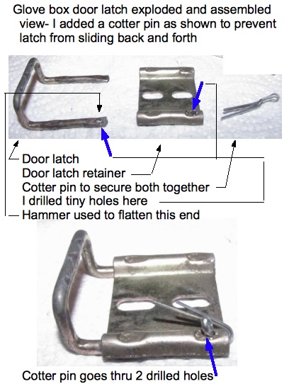
To stop the latch on the door from sliding if it is loose:
1. The door latch on my car was loose (a two piece assembly) and sliding even when tightened so I took it out and flattened with a hammer the back 3/8 inch part of one end of the U shaped piece closest to the hinge.
2. I drilled a tiny hole thru the U shaped piece and the lip on the flat piece it fits in and put a cotter pin through the hole to keep it from sliding back and forth. There is room for a tiny cotter pin. On my car this hole needed to position the parts so that the U shaped part is slid all the way into the flat part it mounts on to mate to the upper latch right:
As information the upper half of the glove box latch on my early 240 is held in place by two 4 MM metric bolts with a .7 pitch.
Preventing door warp by weakening the door light spring:
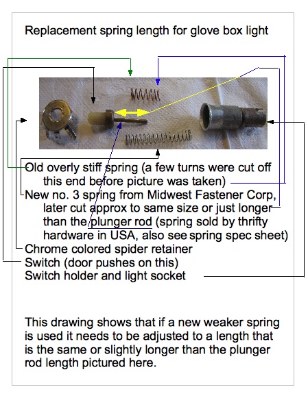
1. To avoid further warping of the glove box door I replaced the spring in the glove box switch with a weaker spring; what Ace Hardware here calls a no. 3 spring.
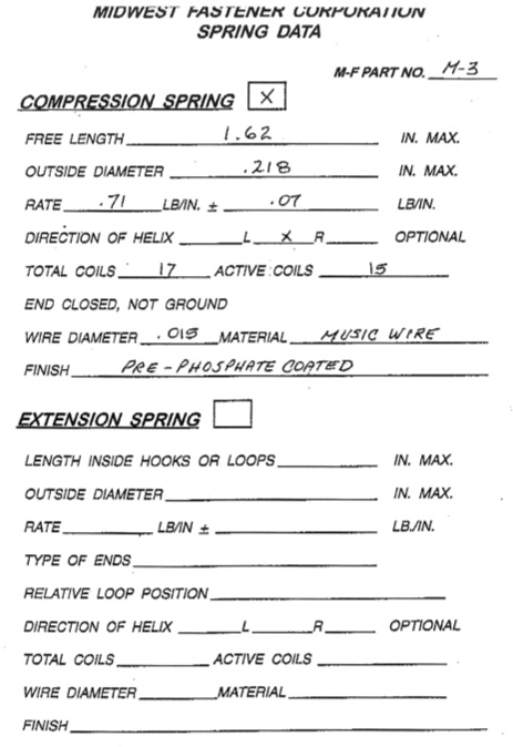
Spring specification:
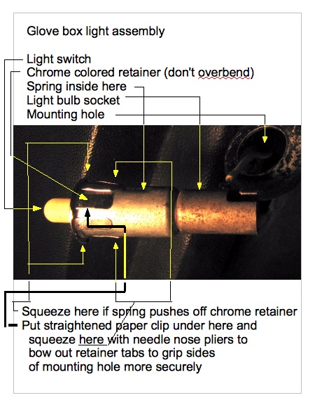
2. The switch assembly, called "nut spring" in the fiche can be pried out with a pocket knife.
3. Bend the legs of the chrome colored retainer out just enough to allow it to pop off of the rest of the assembly. The spring will pop out at this point. The "legs" of this item fatigue easily and will break if bent too much so limit bending as much as possible.
4. I cut off part of the no. 3 spring to make it even weaker however if you do this be sure the spring is still long enough to push the copper connection on the end of the plastic plunger rod into firm contact with the chrome colored retainer as that is where it gets its ground connection. I tried shortening the original spring but the spring still felt too strong. After replacing the chrome colored retainer on the rest of the assembly pull gently to test that the two parts are gripping each other. If not it is possible to gently squeeze the retainer with pliers just under the lip to force the legs to grip tighter. If the legs need to grip the sides of the hole better try putting a straightened out paper clip under a few of the legs in the middle and use pliers to squeeze the end of the leg to force it to bow out so it will grip the hole it fits in better.


0 Comments
Recommended Comments
There are no comments to display.
Create an account or sign in to comment
You need to be a member in order to leave a comment
Create an account
Sign up for a new account in our community. It's easy!
Register a new accountSign in
Already have an account? Sign in here.
Sign In Now