Seppi72
 Subscriber
-
Joined
-
Last visited
-
 That's quite understandable as those of us "up North" don't drive our beauties in the winter and those of us "down South" probably have temperatures that allow for choke-free operation the year round. But maybe someone in the Northwest uses them and it would certainly be good to have this knowledge available on CZCC, Of course, because Webers and Mikunis have completely different operating mechanics from our SU carbs, coupled with changes in fuel compositions since the 1970s, it could be that cold start units simply are obsolete.
 -
I have been planning to put triple Webers on both of my cars since 2019 and have been searching and sometimes posting in this sub-forum for a while. I now expect to be putting the engines together over the winter. While folks talk about their various starting and running problems, jetting recommendations, and so forth, what I've noted is a general lack of pix showing the details of the various setups that must be out there. I've only seen one AFAIK in a post from 2023 (https://www.classiczcars.com/forums/topic/68479-triple-webers-setup/#comments). Could those of you who actually have triple Webers take the time to produce both general and up-close pix of your linkages (OEM pedal to throttle bar or cable) and the various options for mounting (soft or hard mounts; studs or bolts, etc.) and linking (or not) the carbs and why you went the way you did? In conversation with Pierce Manifolds, I've learned that there is actually a "left-handed" cold start module, which would integrate with the existing S30 choke cable setup. The default cold start unit (right-handed) only works if it gets pulled from the front of the engine. So, did anyone ever install a pulley system to allow use of the R/H cold starts with the OEM choke cable setup?
-
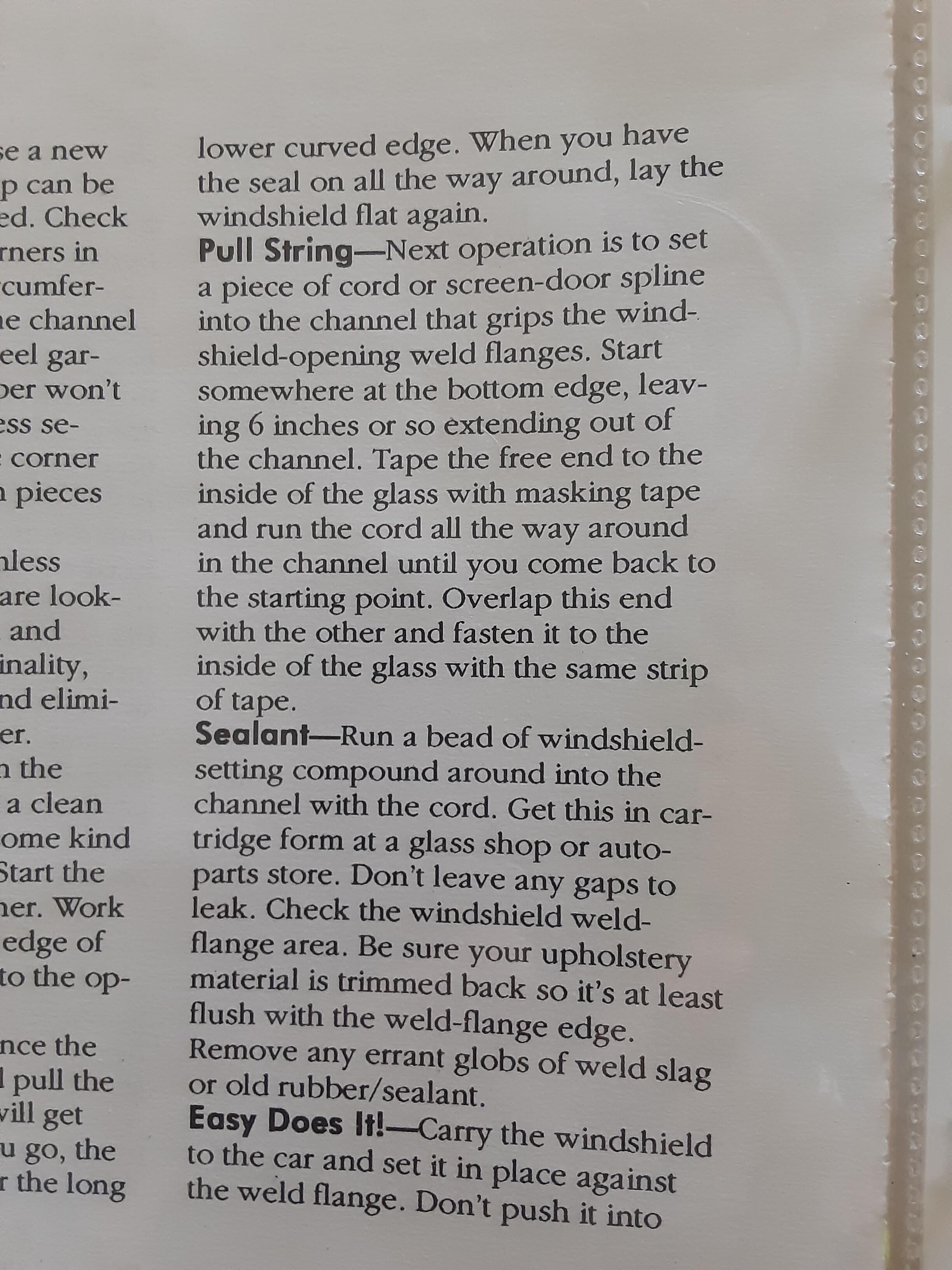
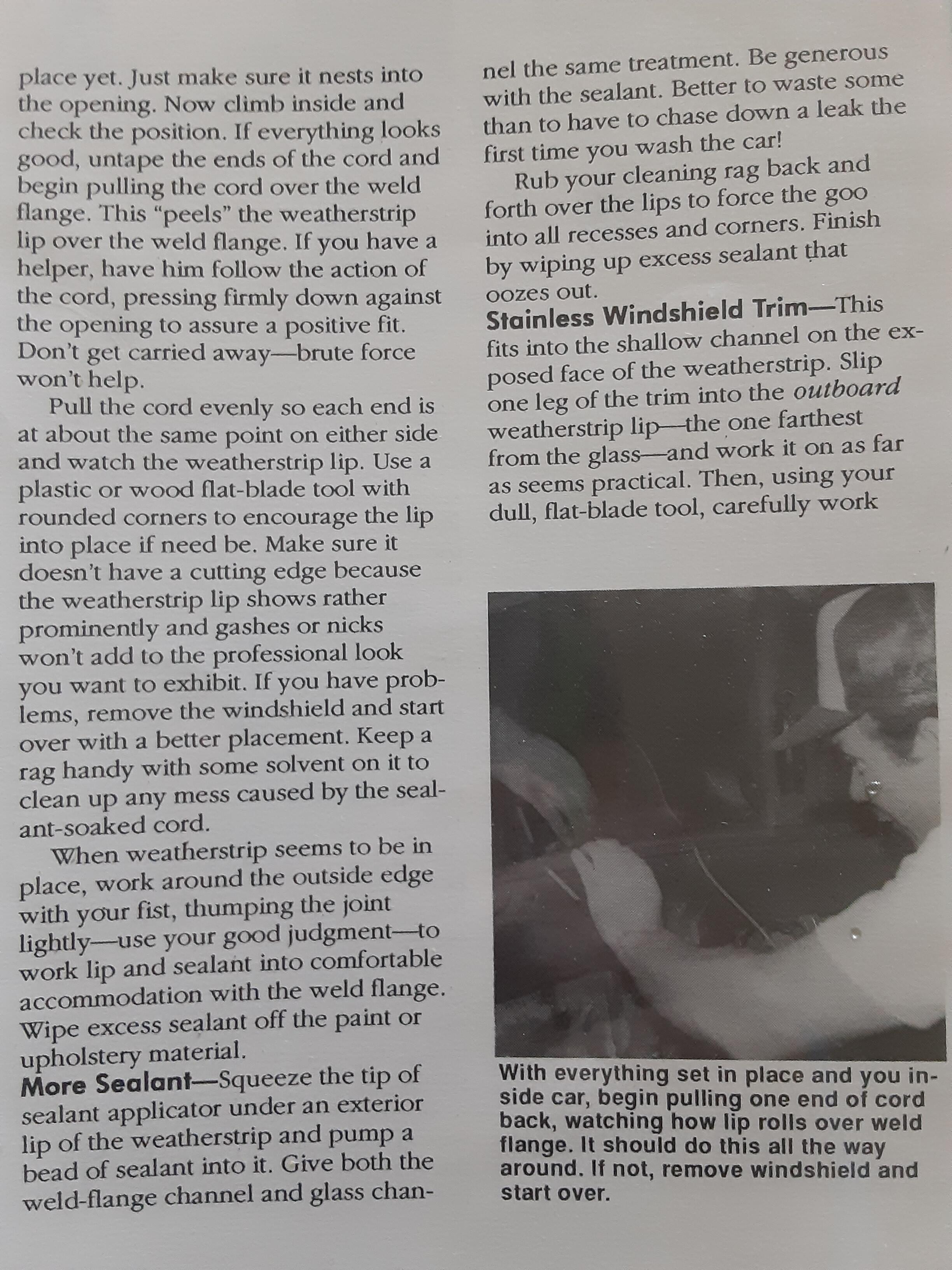
It did strike me as odd that Humble had you snug in the spline and then put a continuous bead of adhesive over it only to pull the spline out later. I can attest that this pulls out most of the adhesive as well. But, who am I to argue with a guy who did it this way and wrote the book on restoring a Z car? Attached photo of Page 130 shows exactly what he said to do. This was for the windshield but he later on says to do the hatch glass the same way. Then, at the bottom of the first column of Page 131 he says to do exactly as you say; i.e., put the sealant under the raised lip of the window. In fact, as I read it, he's saying to do this on all three channels: glass, exterior and interior. This makes eminent sense and really makes me wonder how that first bit of nonsense made it through editing. Oh well, live and learn. Frankly, it's stuff like what I've just been through that makes it all the more important that users of this site comb through all the old threads and extract useful info that can be condensed and put into technical articles for any and all to utilize. I'm trying to do that during my build. Final photo is of my pet Senegal parrot, Koki, eating the marrow out of a chicken bone; a favorite activity. He just loves attention.


-
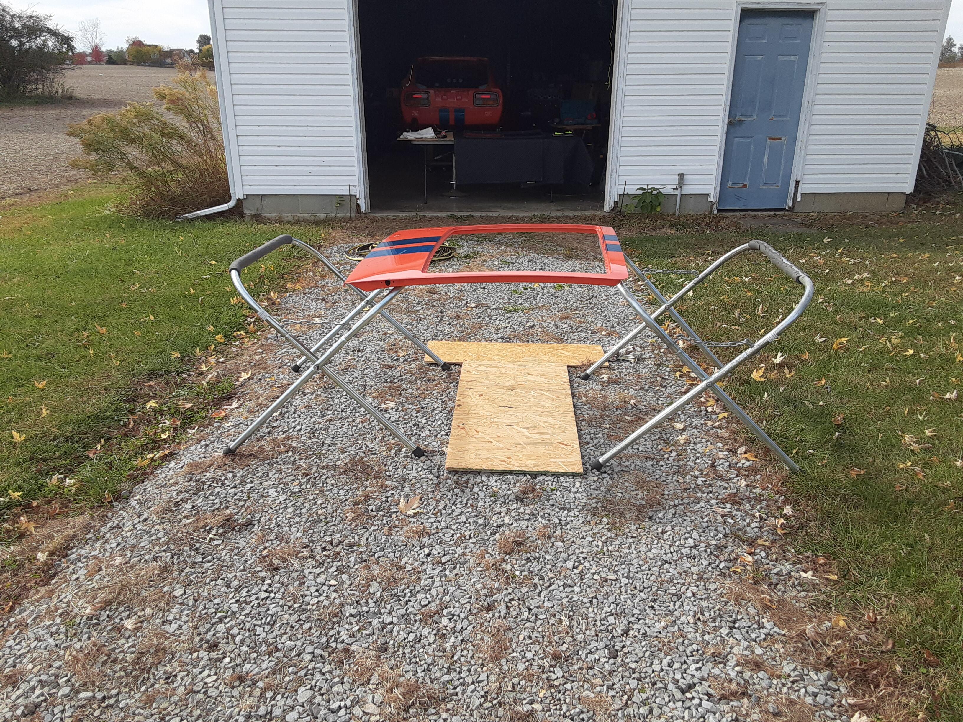
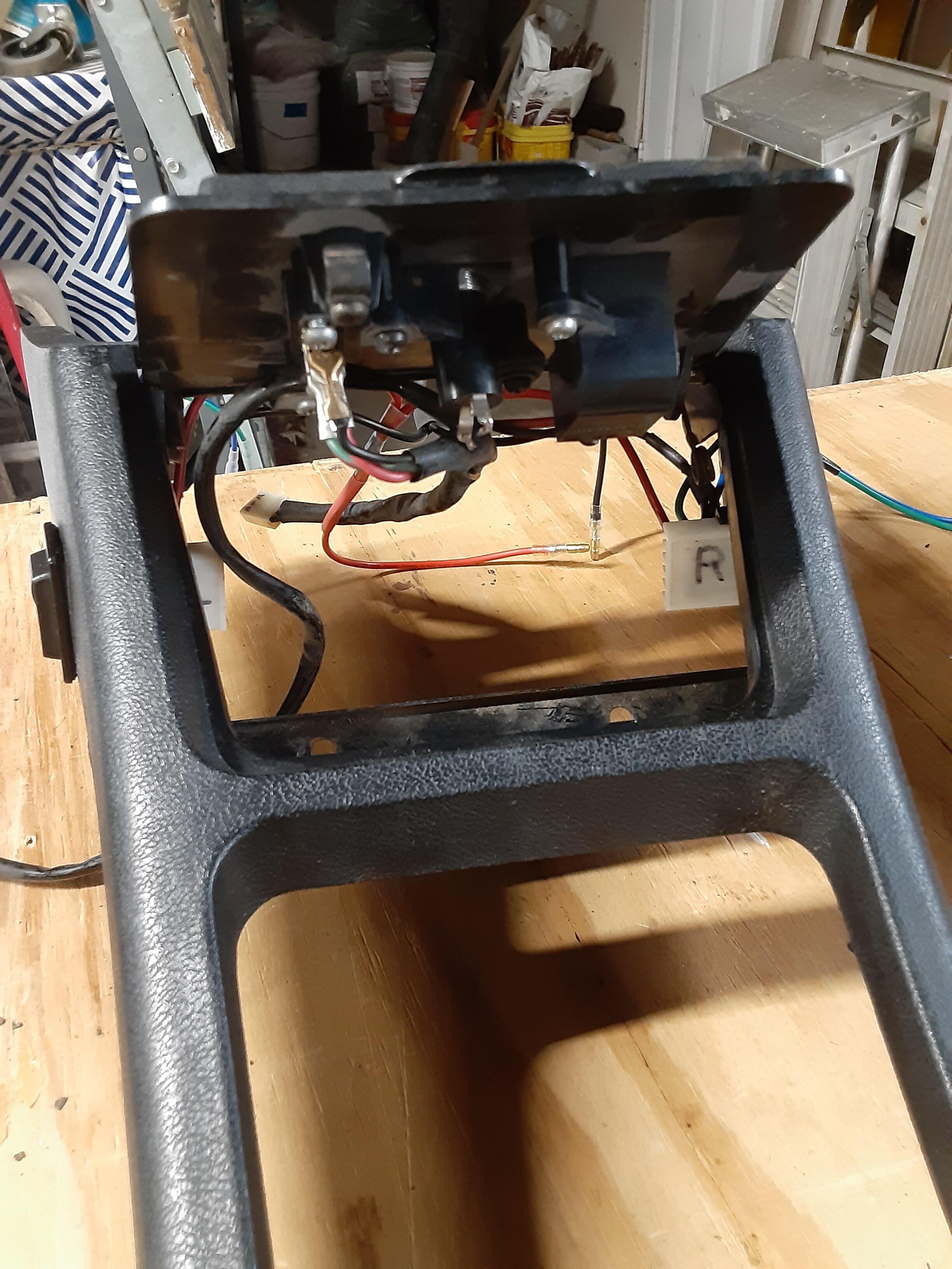
Today, I tried to install the rear hatch glass in my 240 all by myself. BIG MISTAKE. Even though the glass and weatherstrip sat in the channel OK, I simply could NOT get the inner channel to slip over the weld flange, resulting in an adhesive mess. Then spent two hours with paint thinner and a LOT of rags to remove that black adhesive first from my orange metalflake paint and then from the weatherstrip and its flange channel in an attempt to salvage it for another try when I have an assistant to press down on the edges AND the temperature is at least 65 F. That may not be until next spring. SIGH. Maybe I'll bring my set up into the house and do it in my family room AFTER I put down a big plastic "drop cloth." BTW, the hatch was secured to each of those stands so it would not shift or fall. I was following the procedure outlined by Wick Humble in his book How to Restore Your Datsun Z-Car by placing screen spline in the weld flange channel and then laying in a continuous bead of adhesive over top of it. But, with the glass/rubber assembly not sitting low enough in the hatch opening all I managed to do was get adhesive everywhere it should NOT be -- including me. Oy. So, in the end, I did replace all my OEM incandescent taillight bulbs and my choke light with LEDs that came in today from Super Bright LEDs in California. Cold comfort, but progress.

-
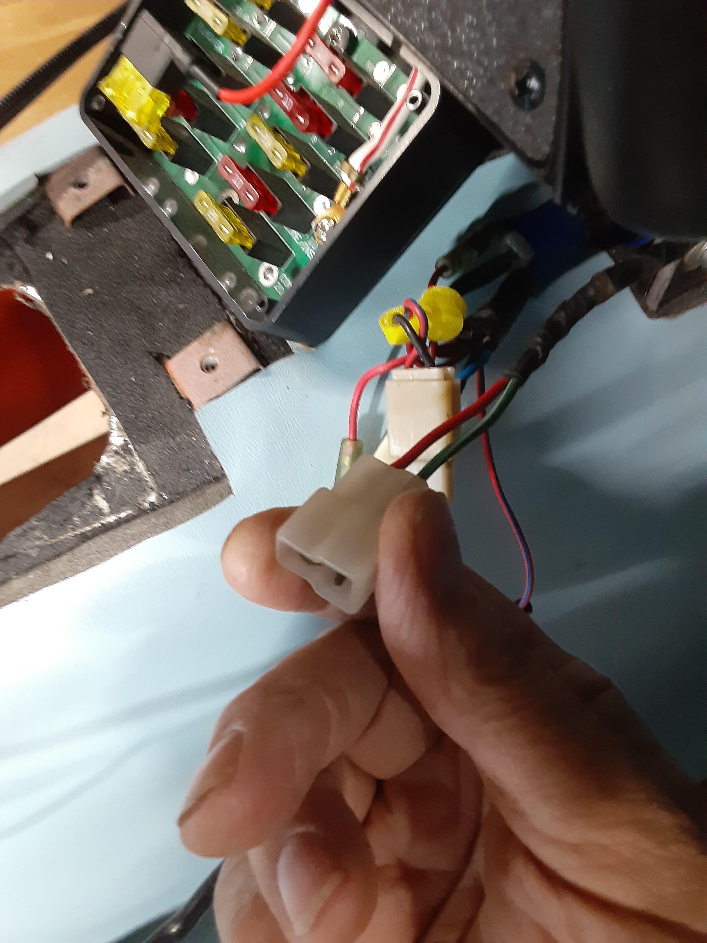
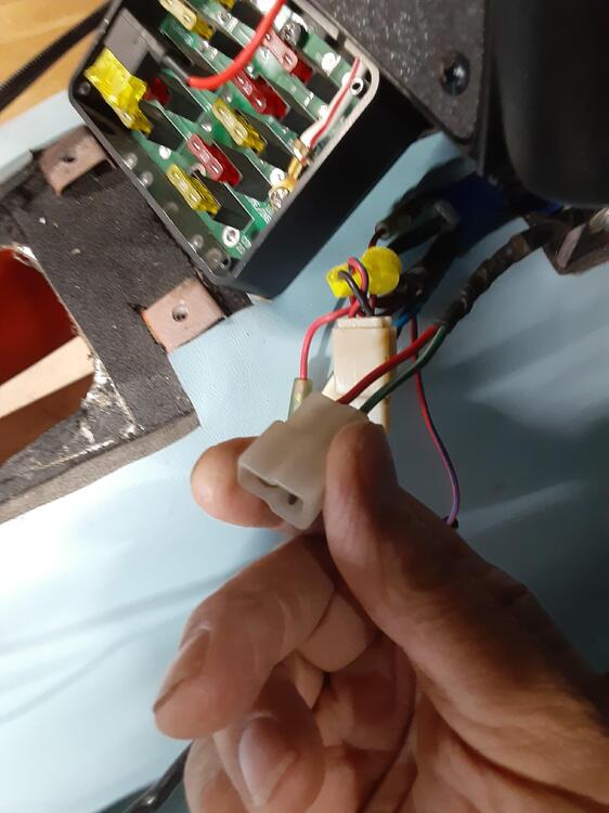
On my early 1972 car (HLS30-46372), this two-wire connector extends from one of the wire bundles that connect with the fuse box. However, I cannot figure out what it's supposed to connect with. It has a red and a green/white wire and I've not seen that combo on any wiring diagram or harness illustration. Any thoughts are welcomed. I do have a later-run '72 car (HLS30-81416) that I could tear into to see what's up there but I'd prefer to not do that if at all possible.
-
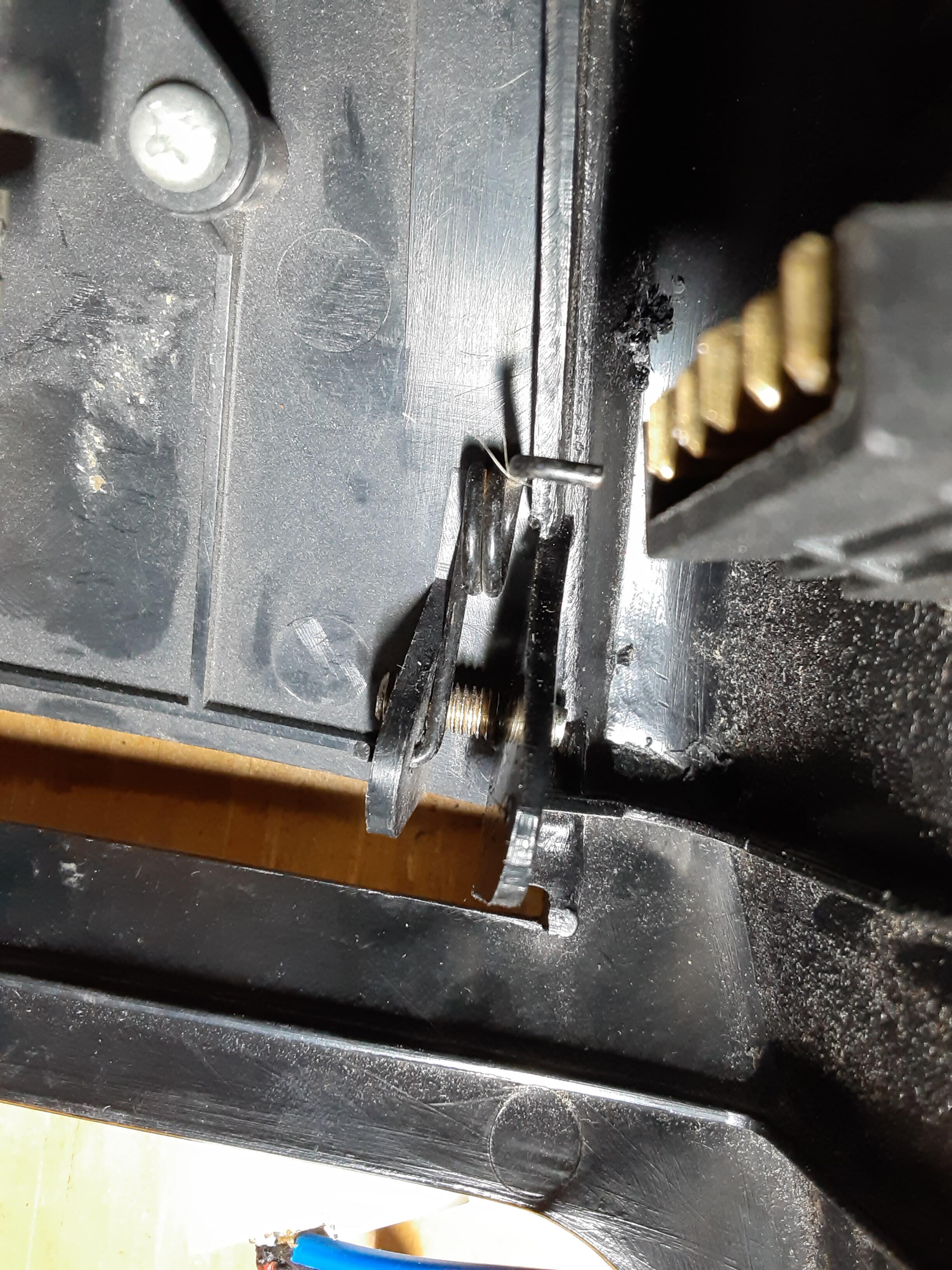
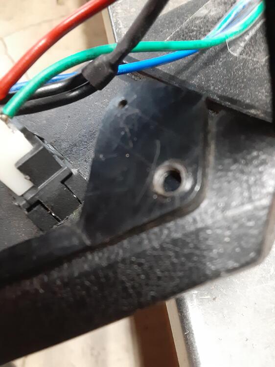
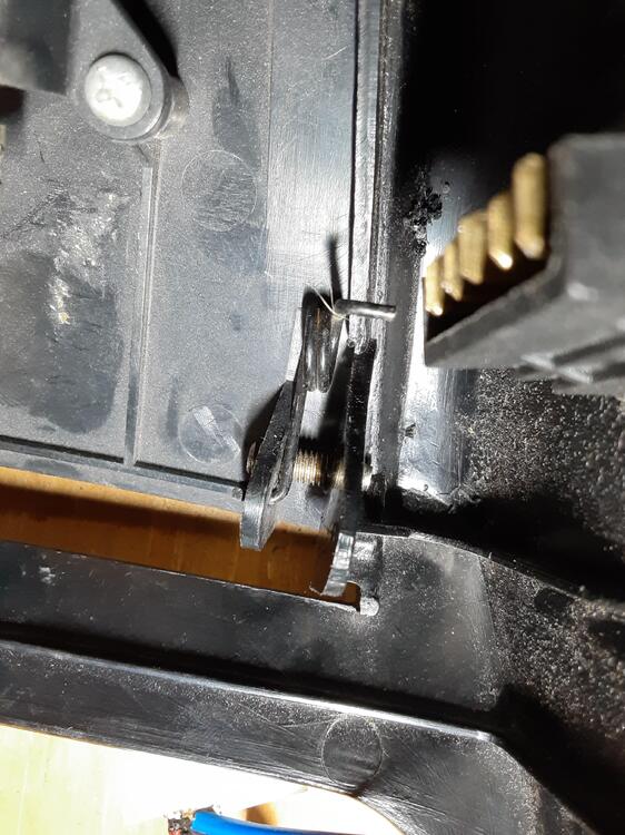
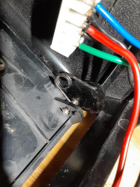
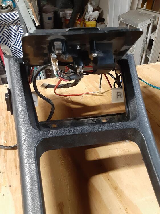
Well, no one came to my aid on this matter so I've solved it as best I could using a metric bolt to replace the missing plastic pin. I measured the left side plastic pin diameter as approximately 4.7 mm. This is close to the 4.7 mm diameter that I measured on a 5M bolt's threads. The hole on the tab on that side of the cover comes in at 5.3 mm so there is about 0.6 mm of "slop" when the pin is in the hole. The hole on the right side tab measured 5.8 mm, almost exactly the diameter I measured for the threads on an M6 bolt. I was a bit squeamish about using an M6 bolt as there would little, if any, of the kind of slop as exists on the other side. So, an M5 bolt it was. But I do have the option of swapping in an M6 if I feel the need. I started by creating a small divot in the middle of the broken pin's location. Then, starting with a 1/16" drill bit (Hey, I ain't got metric drill bits), I gradually increased the hole size step-by-step using the next larger drill bit until i finished with 5/32" bit. I then slowly tapped the hole with a 5 mm-0.8 tap. Note that my tap and die set says to use an 11/64" drill for this but I wanted to have plenty of plastic "meat" for the tap to bite into. With that done, I took a 5M-0.8 x 30 bolt and cut off the hex head to give me a crude stud. I threaded this into my hole so that just a little tip of the stud showed on the side where the tab would eventually be. I then put the cover on the remaining plastic pin and, using needle-nose pliers, rotated the M5 stud so it engaged with the tab hole and then a bit more for good measure. I was going to epoxy the M5 stud into place but decided to not do so now at least because things are working well and it will be easy to retract the stud if I need to remove the cover at some point. I LOVE field engineering.
-
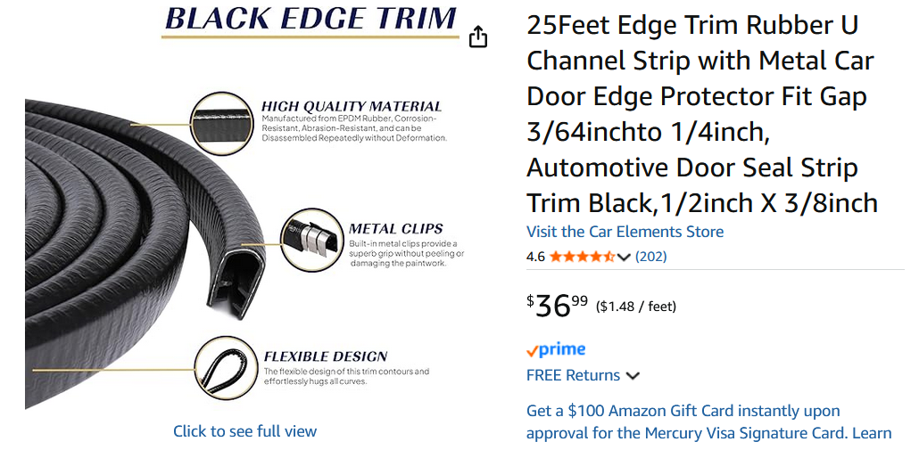
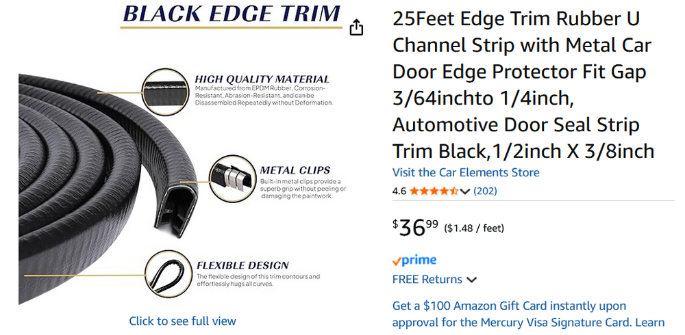
There are sources for the OEM gripper strips and I bought 25 feet of it on Amazon (nice stuff, BTW, and I used some of this channel, in white, around my interior roof line) before I got my Precision weatherstrip kit and saw the gripper integrated into the door seal. If anyone wants it, let me know and we'll work a deal.
-
Could AI be smarter than marketers? Better speller for sure.
-
Right you are, Zed Head, as temperature, humidity and the area actually exposed to atmosphere are the critical variables. And, don't blame Amazon for that spelling. It's what is on the cartridge itself. Ah,marketers... Many's the time I've had fascinating discussions with the ones I worked with. Always looking for that "hook" to drive customer recognition and product uniqueness. Sometimes a few weren't securely tethered to reality. I remember one asking if I could replace air with something less expensive. 🙄
-
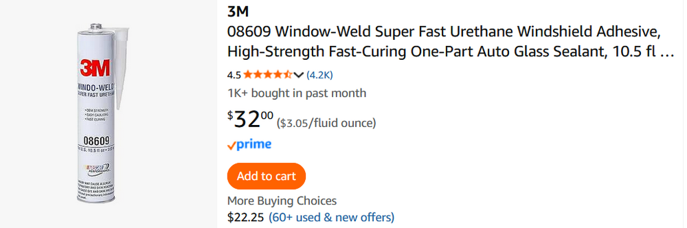
That's 3M's marketing terminology and being a chemist who has worked with one-component urethanes, I know the many variables involved. BTW, I spoke today with a local auto service shop owner who has many collectible cars and has installed several windshields over the years. He advised that the 3M product is what should be used but not to bother with using it in the channel where the glass goes unless the car will be parked outside or driven in the rain regularly. Wick Humble's restoration book also does not advise using any adhesive in this channel during glass insertion. He also advised to place the windshield on the car without first applying the urethane to the weld flange and then to "backfill" the inner part of the weld flange channel with urethane. Humble advises putting adhesive into the weatherstrip's channel before installation and then backfill both the exterior of the weld flange AND glass channels with adhesive once you're satisfied with the placement. Makes sense to do that on the exterior portions so I'll see what things are like when I get to that point. Finally,as for the door weatherstrip, my local guy says to put it in "dry" and only use some 3M Yellow Super Weatherstrip and Gasket Adhesive at the point where the two ends meet up on the door sill.
-
So, I bought a cartridge of 3M Windo-Weld Super Fast Urethane adhesive to use when I set my windshield. It's $44 at my local NAPA store but I see it for $32 on Amazon. Do you who have done weatherstrip replacements think this will be good for the door weatherstrip as well? It sure seemed as though the OEM weatherstrip had a "permanent" adhesive used on it.
-
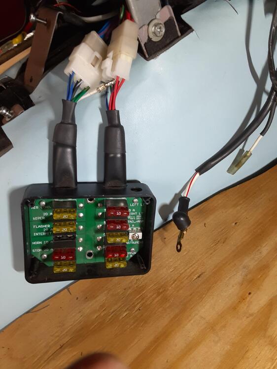
I have these two wires hanging in close proximity to the connectors that attach to the 6-lead plugs coming out of the fuse box - a thick white/red and a "normal" white (that had been covered by a black sleeve. Because of the proximity, I'm confident that the white wire connects with the white wire coming out of the left side bundle from the fuse box and services the horn circuit. I think I have a good idea of where the white/red wire goes but want confirmation from one of our electrical gurus. Because it is finished with a lug, it is supposed to be held on somewhere with a screw or bolt and I think that place is the metal block located around 3 o'clock on the MSA fuse box. On my other '72 that has the OEM fuse box, the white/red wire disappears underneath the box and I haven't torn things apart to see exactly where it attaches. Can someone verify that this white/red wire does indeed go on the screw mount inside the MSA fuse box?
-
Pretty sure I know the answer, but for confirmation's sake, I'll ask. First, the set-up. Just got a new Precision complete weatherstrip kit for my 1972 240Z. The door strips in the kit are quite a bit different from the OEM ones in that they have a "gripper" channel (see Photo 1) whereas the OEM strips have but a thin U-channel (see Photo 2). I believe this was a design change made for the 280Z. Both of these are meant to attach to the metal weld and quarter window flanges around the door openings. The OEM strip's grip on the flanges is then reinforced with a stiff U-channel (Photo 3) that covers all but a small section of flange along the bottom of the door opening where the inner scuff plate does the job In his book "How to Restore Your Datsun Z-car", author Wick Humble said (page 135) that the factory's 280Z-style weatherstrip comes preloaded with a "non-hardening adhesive/sealant in the "U" of the weld flange trim that was not previously specified." Clearly, the strips I got from Precision do not have such a preloaded material So, my question to you fine folks is this: Should I apply some kind of adhesive/sealant in the U-channel and, if so, what would you recommend? I'm already using 3M Yellow Super Weatherstrip and Gasket Adhesive on the rest of the car that needs such a material.


-
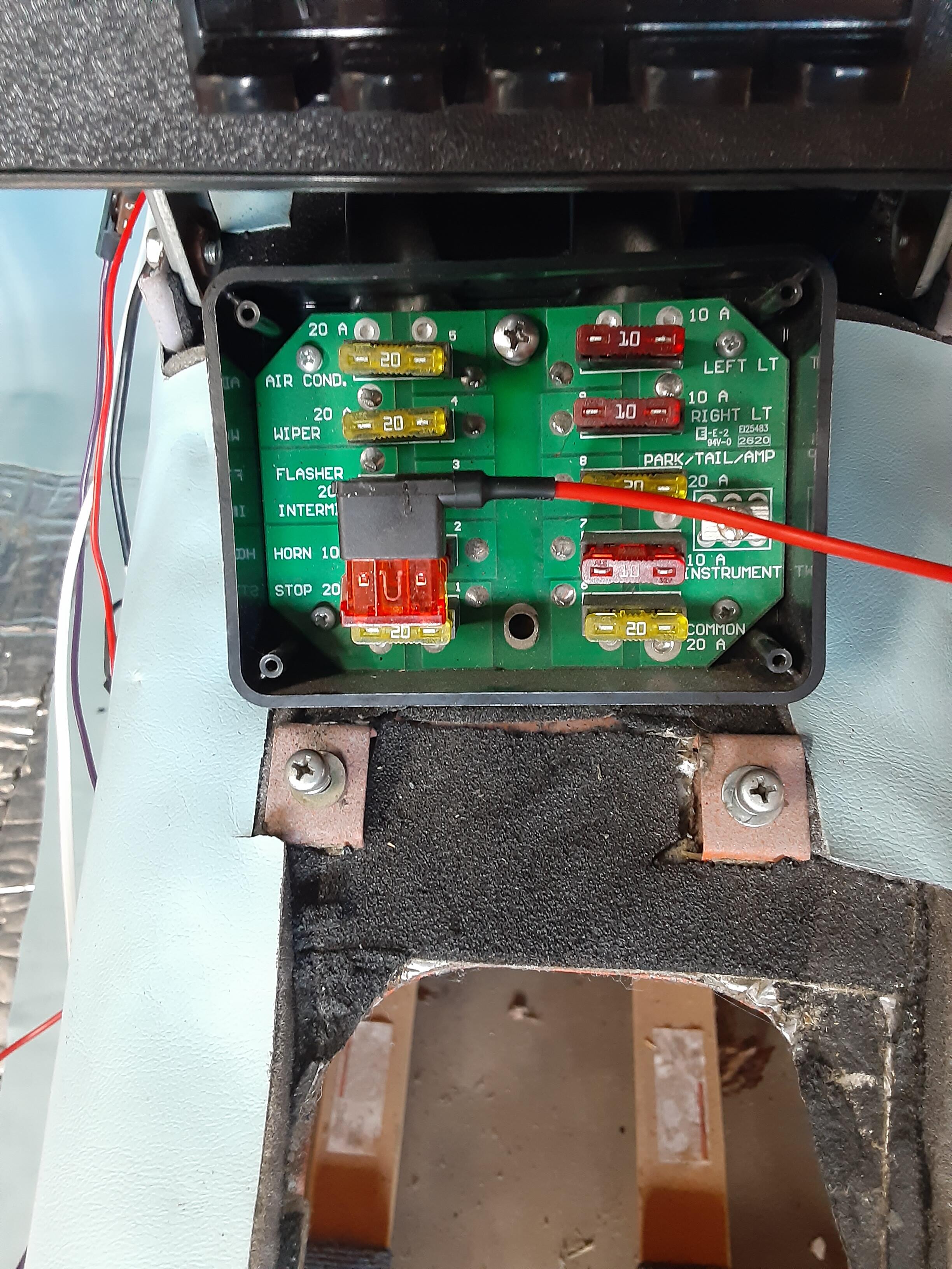
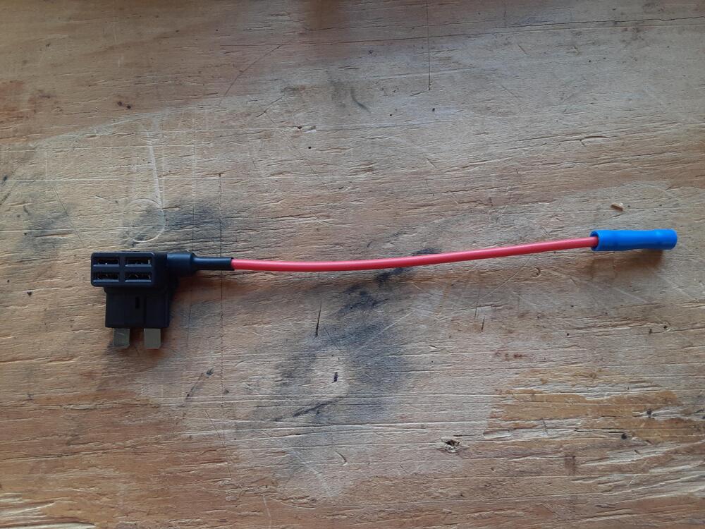
I may have inadvertently covered up that wire when I re-wrapped all my harnesses several years ago (what a FUN time that was). In any case, I've decided to go with a fuse tap in the main fuse box on the 20 A FLASHER fuse, which is the only circuit in the box that is KEY-ON activated. Will use a 10 A fuse for my Retrosound Motor 4 radio, Vintage Air HVAC controller and Valentine One radar detector. Frankly, until yesterday I didn't know such a thing as a fuse tap existed. Ran across it when searching online how to hard-wire my radar detector. Really happy now that I swapped the OEM fuse box for an ATO-style one from Motorsport Auto.

-
It occurred to me today as I was reinstalling the dashboard (after 17 years) that because I have completely separate wiring for the Vintage Air HVAC system, I mighty just take the power intended for the OEM heater/blower and use that instead of finding a KEY-ON wire. Yes, I know that circuit is activated in the ig-switch's ACC position but because I don't have adolescents who will want to listen to the radio when the car is not running, that might be a good option.