


Dave WM
Free Member
-
Joined
-
Last visited
Everything posted by Dave WM
-
 this use of movies subplosts to communicate reminds me darmok
 -
Since its adjustable from 0-100 you can use it with any of the bulbs actually just depends on how much resistance you add, less with the high resistance bulb, more with the low resistance bulb. you just need to adjust the setting to what works. the bulb and the thermistor both vary resistance with heat, the pot is the only thing that once set does not vary. The pot is just a work around for a system that can not stabilize in to a low current steady state while submerged. There is something fundamentally wrong as is, but at this point its got to be either the performance of the thermistor OR for some reason the gas is not cooling the thermistor as designed. The bulb is the only other variable and with the selection you have to choose from that should not be an issue.
-
you may want to use the dimmest bulb and just see if it works as designed when you run low, of better still, if yours it a top loader, I would say just pull it up until you can see the thermistor is not submerged, the see if it works, it should come on brighter in a few minutes. That way you will at least know the system is seeing the change in submerged vs not submerged. From there you can determine the max brightness to determine if you can live with the bulb #1 Maybe you can say that the dim always on is a way to confirm the system is active if the rest of it works as it should. This is actually a good idea if the dim light is not annoying. (see "andromeda stain" paper in bell clapper reference for Capt O)
-
I am posting up a video, will link here, showing my hookup and how it effect brightness of the lamp. I can control the horz I can control the vertical, …. ok CO what show is it...
roger that, so any more than 50ohms added it a waste of time as it will keep the light from functioning. I have my doubts about the feasibility of the pot fixing the issue, seems as you say it really needs to work as it is supposed to (correct specs on thermistor), but short of that I have a 50 ohm WW pot ready to go to Dr. Dave. He is messing with some other bulbs now. I think I will get a cold filament resistance reading of my car and report back. lamp at leads that plug into wire harness resistance 6.0 ohms
roger, I have a 150 ohm WW pot think its 2 watt rated (it will get warm, so really just use to size the correct fixed resistor once the value is known) ready to send. Would like Capt O to confirm my value as a good starting point (any higher resistance I think would render the light dark not matter what the sender does). You would want to use some jumper wires (3) to insert in series with the connector plug that you back probed. 1 jumper is a direct pass thru, the other two connect the pot between the remaining plug lead. Start off with max resistance and see if the light stays off, if it does, then you can sneak up on the lower resistance until it just starts to light, back off and you should be good. Note the resistance value and substitute the pot for a 5 watt WW resistor. This all assume it actually works and you are not able to get it to work with the other bulbs. incase it was not already covered regarding bulb experiments: On the other bulbs, remove the current installed one, check the resistance , then check the replacements. pick the one that has the highest resistance. We are trying to limit the current to keep the thermistor from self heating beyond what the fuel cooling can dissipate. install the highest resistance bulb and try again. This is the same as adding the pot in series and adding resistance with it.
since your reading of .93k at even 125f there is no way that light should come on CO says more like 230ma to glow full so I would guess you need prob a min of 75ma to notice it. that being the case the thermistor must be getting much hotter that 125f. more on the order of .15k or 150 ohms to flow about 80mA just to get it to light dimly. So the issue now become if you insert a pot to lower the resistance in an effort to keep the light from coming on, anything more that 150 ohm in series with the thermistor will prob keep it from lighting no matter what the thermistor is doing. therefore any added resistance should be no more that 150ohms and clearly more than 0 (otherwise it has not benefit). I will dig around my pot stash and look for a 100 ohm WW rheostat. I have some that were used in old color convergence boards for TV's in the vacuum tube era.
be glad we are not talking about capacitors and Farads... Capt, I remember using uuf vs pf...
milli often used in electronic terms as 1/1000th so 1000mA = 1 amp the math I used was ohm law current in amps=volts / ohms so you had .943k ohms or 943 ohms (in resistance K is 1000, confusing eh?) 12 volts/943 ohms= .0127 AMPs .0127 AMPS * 1000 to convert to milliamps 12.73 mA rounded to 13mA Lots of times values are stated as milliamps or mA due to the smallish current and its easier to say 130mA that .013Amps
my cowl has the scar to prove that statement..
I think I did my math wrong, current = 12/943*1000 (milliamp) 13mA no where near enough.
yes I would def replace any missing dowels, they are there to precisely align the bell (and therefore the input shaft to the pilot). Installing the bell to the engine is one of those things that you can mess with for hours laying on you back trying to get it to go, or sometimes a couple shakes and its in. I like the trans jack and the engine floor jack (using suitable 2x6 to distribute load) and then get them close use the guide bolts, and adj both engine and bell so the gap looks even. You have to get the angles right sometimes adj the engine up or down helps. I don't recall the dowel types or location just that they were there.
heating from within (current passing thru a resistor)or outside (hot water heating up the resistor) should have the same effect, drop in resistance. I don't know the specs of the thermistor so really just guessing as to what temps things happen. The only hope is a resistor in series with the circuit will keep the already high resistance (3k) a bit higher to keep the thermal runaway from happening (more heat generated than is dissipated by the fluid surrounding it). adding resistance will how ever limit the overall max current allowed (a fixed resistance in series) so as to limit the brightness the lamp could ever achieve. Sounds like a balancing act that Nissan got right but is hard to reproduce from you experience. Has the vendor commented on any of this? would be nice to hear that they have fielded working units.
in order for that light to come on you have to get much lower resistance, at 12/943 ohms is .013 amps or 130mA seems low. CO needs to chime in... just guessing really as to the normal operating parameters. maybe it self heat up to a much lower resistance. Must be for the light to come which means the thermistor is sitting in a hot hot pool of gasoline to turn on. maybe 124f is still not that hot, try boiling hot. that has to turn it on with a much lower resistance. feel free to ignore that last bit about boiling, I am just guessing now, but would like to see that resistance get down to about 100ohms (.1k)
I am afraid I am at a loss for any other help. Let me know if you want to try the rheostat, but I honestly wonder if that will help. The whole system in predicated on a variable resistance. Try used a different light while monitoring the voltage at the lamp connectors. You want to drop that mV reading below what you are seeing now.
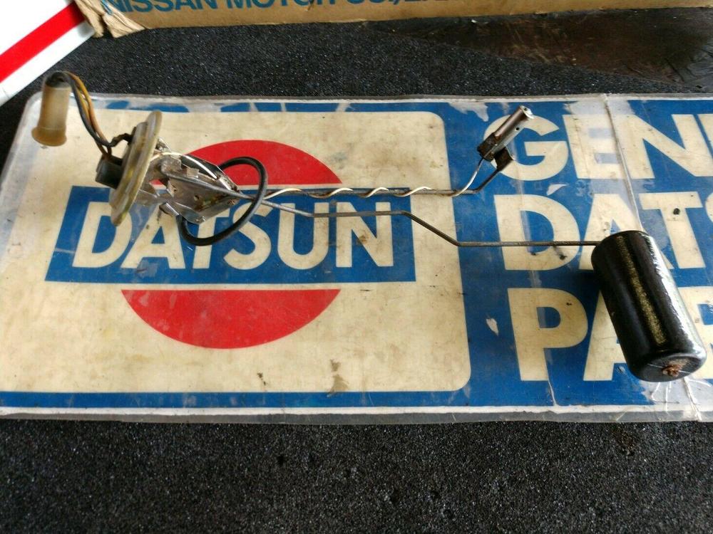
is there holes on the top plastic part? see the below OE one
 pretty much exactly the same I get. the only other test you can do on the installed sender would be to keep an eyeball on it and see how long it takes to start ramping up, it has to for the bulb to come on, but at this point I would say the only thing left is the thermistor is not really in the gasoline due to perhaps a blocked hole in the can or some other manufacturing defect that is insulating it from the cooling effect of being immersed in a fluid.
another test for the one on the bench. test the ohms, then stick the can in some hot water, see if it changes. I am trying to confirm the thermistor is actually seeing the fluid it is immersed in. in the hot water the resistance should go down A LOT and it should happen fast (seconds). if the change is very gradual or not at all then you have the answer. I think this test is more important than the prior suggestion, I suspect the back probing will only confirm that you have approx. the same starting voltage, and give a data point on how long it takes to go to max voltage and what that is. this latest test addresses perhaps the only other possible cause assuming everything else is correct (hookup, voltages, thermistor properties). a lack of physical contact with the coolant (gasoline) fits the problem. the 25min to full on well I get there in about 5 min, could be the thermistor curve, but it should still work as long as the cooling fluid is allowed to come and go to activate the system.
here is a thought is it possible the thermistor in the can is not actually coming into contact with the gas? on my thermistor the can has holes in it to allow fuel to enter and exit the can. IF for some reason this was not the case in the new sender, then the cooling effect would be lost. You should see bubbles come from the can when inserted into a fluid, and likewise fluid should drain out when removed. Not a lot mind you, but something showing the gasoline is actually coming into contact with the thermistor.
I think it would be a good idea to try the back probe the connector at the center console. This is the white connector that is on the lamp harness wire, and the connector that is part of the wire harness that runs along the firewall. Its the one you have to undo (along with a bunch of other) that when you are pulling the center console off. You know you have the right connector when if you UNPLUG it then back prob it should be 12v with the key in the "run" position. Its 12v since there is no lamp load plugged in. The 3k ohm resistance will not drop any voltage since the circuit is open (no lamp, and the meter is not enough of a load to effect it). As soon as you plug the lamp in with the probs still in place the lamp load will cause a current to flow and the voltage will drop due to the high (3k) resistance. The point to all this is to try and duplicate a known working system (mine). so far the resistance of the thermistor checks out the same, so I am curious to see if you have the same starting voltage (lamp load and battery will effect that), and then watch it to see how fast it ramps up. I will pm you my phone number if you want to talk thru it when you are ready to test.
you are just not getting the input shaft to fit the pilot, re check the clutch install with the installation tool. when tightening up the pressure plate you want to make sure its centered, it can go in and droop a bit. I suspect the plastic tool is part of the problem, anyway eye ball the tool to make sure its 90 degrees and goes in easy. I hope you have a proper jack stand for the trans, as you go in try to make sure the gap is even all around then you just have to shake and work it on. I used guide bolts (long bolts with the heads cut off, sloted for removal) on diagonal sides to help hold the trans in place while doing this. it will go but you absolutely do not want to force it by using bolts to pull it up. Hopefull the pilot bush is not bunged up, that may add to the problem. oh and I assume the dowel pin are installed ? they provide for a precise alignment of the bell housing to the block.
I used a butyl compound that has its own pump can and a small metal tip that lets you get under the gasket. Works great but is super messy, the butyl from what I understand is just some kind of uncured rubber, it get messy fast when applying, practice would be a good idea before attempting to do on the car. I think CO was with me when it started to rain and water came thru, ha. member dat CO? No more leaks since that fix. I also used the butyl to tidy up where the various rubber gaskets that seal off the door, and the wiper strip on the window connects to the chrome molding.
hmmm well there you go, very close to what I got. for cold resistance. So just that I am clear, right now with all hooked up and gas in tank say at least 1/2 way full, the light will come on after about 25 min and stay on? If that is the case, seems like the next logical step will be to back probe, and check the lamp voltage from off to on over the 25 min period. will talk about that later, but its what I was doing in the video. You just have to find that plug, set the voltmeter to volts, and insert in the back so the probes contract the inside of the plug. I am assuming starting with the "2000m" to see if you get a reading if not switch down to "200m"
it can be kinda hard to hold the dvm probes on the sending unit. some jump wires (alligator clips on wires) are a handy way to grab the pins on that sending unit. Just clip onto the black wire and the yellow/blue wire, set dvm to ohms and if auto range you should get the reading. If its not auto ranging start out at the 1k setting and go up or down from there until you get a reading. Test the setup of the meter by shorting the two leads, should be 0 ohms. always test... test equipment before relying on results. this is to test the resistance of the sending unit on the bench. My sending unit was about 3kohms (3000 ohm). all the above test are done with the sending unit out, no voltage required, you are just testing resistance. The back probing I was talking about was aimed at capt obvious, the assumption is his setup is working so I was wondering what the key on/lamp off voltage was. Mine is about 30-50mV as long as the thermistor is in the gasoline. This test requires everything hooked up and the key in the (run) position. (.03-.05v), starts there and takes about 5 min to get to .250v (250mV) once there it quickly goes to 6-8v that is after its not immersed in gas (low fuel, I presume about less than 2 gallons usable fuel left in tank).
pretty much exactly the same I get. the only other test you can do on the installed sender would be to keep an eyeball on it and see how long it takes to start ramping up, it has to for the bulb to come on, but at this point I would say the only thing left is the thermistor is not really in the gasoline due to perhaps a blocked hole in the can or some other manufacturing defect that is insulating it from the cooling effect of being immersed in a fluid.
another test for the one on the bench. test the ohms, then stick the can in some hot water, see if it changes. I am trying to confirm the thermistor is actually seeing the fluid it is immersed in. in the hot water the resistance should go down A LOT and it should happen fast (seconds). if the change is very gradual or not at all then you have the answer. I think this test is more important than the prior suggestion, I suspect the back probing will only confirm that you have approx. the same starting voltage, and give a data point on how long it takes to go to max voltage and what that is. this latest test addresses perhaps the only other possible cause assuming everything else is correct (hookup, voltages, thermistor properties). a lack of physical contact with the coolant (gasoline) fits the problem. the 25min to full on well I get there in about 5 min, could be the thermistor curve, but it should still work as long as the cooling fluid is allowed to come and go to activate the system.
here is a thought is it possible the thermistor in the can is not actually coming into contact with the gas? on my thermistor the can has holes in it to allow fuel to enter and exit the can. IF for some reason this was not the case in the new sender, then the cooling effect would be lost. You should see bubbles come from the can when inserted into a fluid, and likewise fluid should drain out when removed. Not a lot mind you, but something showing the gasoline is actually coming into contact with the thermistor.
I think it would be a good idea to try the back probe the connector at the center console. This is the white connector that is on the lamp harness wire, and the connector that is part of the wire harness that runs along the firewall. Its the one you have to undo (along with a bunch of other) that when you are pulling the center console off. You know you have the right connector when if you UNPLUG it then back prob it should be 12v with the key in the "run" position. Its 12v since there is no lamp load plugged in. The 3k ohm resistance will not drop any voltage since the circuit is open (no lamp, and the meter is not enough of a load to effect it). As soon as you plug the lamp in with the probs still in place the lamp load will cause a current to flow and the voltage will drop due to the high (3k) resistance. The point to all this is to try and duplicate a known working system (mine). so far the resistance of the thermistor checks out the same, so I am curious to see if you have the same starting voltage (lamp load and battery will effect that), and then watch it to see how fast it ramps up. I will pm you my phone number if you want to talk thru it when you are ready to test.
you are just not getting the input shaft to fit the pilot, re check the clutch install with the installation tool. when tightening up the pressure plate you want to make sure its centered, it can go in and droop a bit. I suspect the plastic tool is part of the problem, anyway eye ball the tool to make sure its 90 degrees and goes in easy. I hope you have a proper jack stand for the trans, as you go in try to make sure the gap is even all around then you just have to shake and work it on. I used guide bolts (long bolts with the heads cut off, sloted for removal) on diagonal sides to help hold the trans in place while doing this. it will go but you absolutely do not want to force it by using bolts to pull it up. Hopefull the pilot bush is not bunged up, that may add to the problem. oh and I assume the dowel pin are installed ? they provide for a precise alignment of the bell housing to the block.
I used a butyl compound that has its own pump can and a small metal tip that lets you get under the gasket. Works great but is super messy, the butyl from what I understand is just some kind of uncured rubber, it get messy fast when applying, practice would be a good idea before attempting to do on the car. I think CO was with me when it started to rain and water came thru, ha. member dat CO? No more leaks since that fix. I also used the butyl to tidy up where the various rubber gaskets that seal off the door, and the wiper strip on the window connects to the chrome molding.
hmmm well there you go, very close to what I got. for cold resistance. So just that I am clear, right now with all hooked up and gas in tank say at least 1/2 way full, the light will come on after about 25 min and stay on? If that is the case, seems like the next logical step will be to back probe, and check the lamp voltage from off to on over the 25 min period. will talk about that later, but its what I was doing in the video. You just have to find that plug, set the voltmeter to volts, and insert in the back so the probes contract the inside of the plug. I am assuming starting with the "2000m" to see if you get a reading if not switch down to "200m"
it can be kinda hard to hold the dvm probes on the sending unit. some jump wires (alligator clips on wires) are a handy way to grab the pins on that sending unit. Just clip onto the black wire and the yellow/blue wire, set dvm to ohms and if auto range you should get the reading. If its not auto ranging start out at the 1k setting and go up or down from there until you get a reading. Test the setup of the meter by shorting the two leads, should be 0 ohms. always test... test equipment before relying on results. this is to test the resistance of the sending unit on the bench. My sending unit was about 3kohms (3000 ohm). all the above test are done with the sending unit out, no voltage required, you are just testing resistance. The back probing I was talking about was aimed at capt obvious, the assumption is his setup is working so I was wondering what the key on/lamp off voltage was. Mine is about 30-50mV as long as the thermistor is in the gasoline. This test requires everything hooked up and the key in the (run) position. (.03-.05v), starts there and takes about 5 min to get to .250v (250mV) once there it quickly goes to 6-8v that is after its not immersed in gas (low fuel, I presume about less than 2 gallons usable fuel left in tank).


Important Information
By using this site, you agree to our Privacy Policy and Guidelines. We have placed cookies on your device to help make this website better. You can adjust your cookie settings, otherwise we'll assume you're okay to continue.