Captain Obvious
Free Member
-
Joined
-
Last visited
Everything posted by Captain Obvious
-
 That's exactly what I did. Perfect!
 -
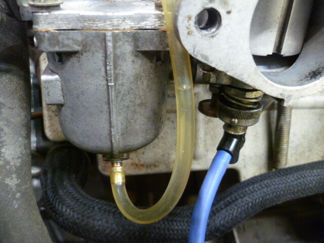
That little adapter hose with the banjo is great for later round tops with the drain fitting. Same for the float-sync device. If you have earlier carbs without the drain, a little piece of tubing on the bottom of the bowl works. Down side is you can only use it static with the engine off.
-
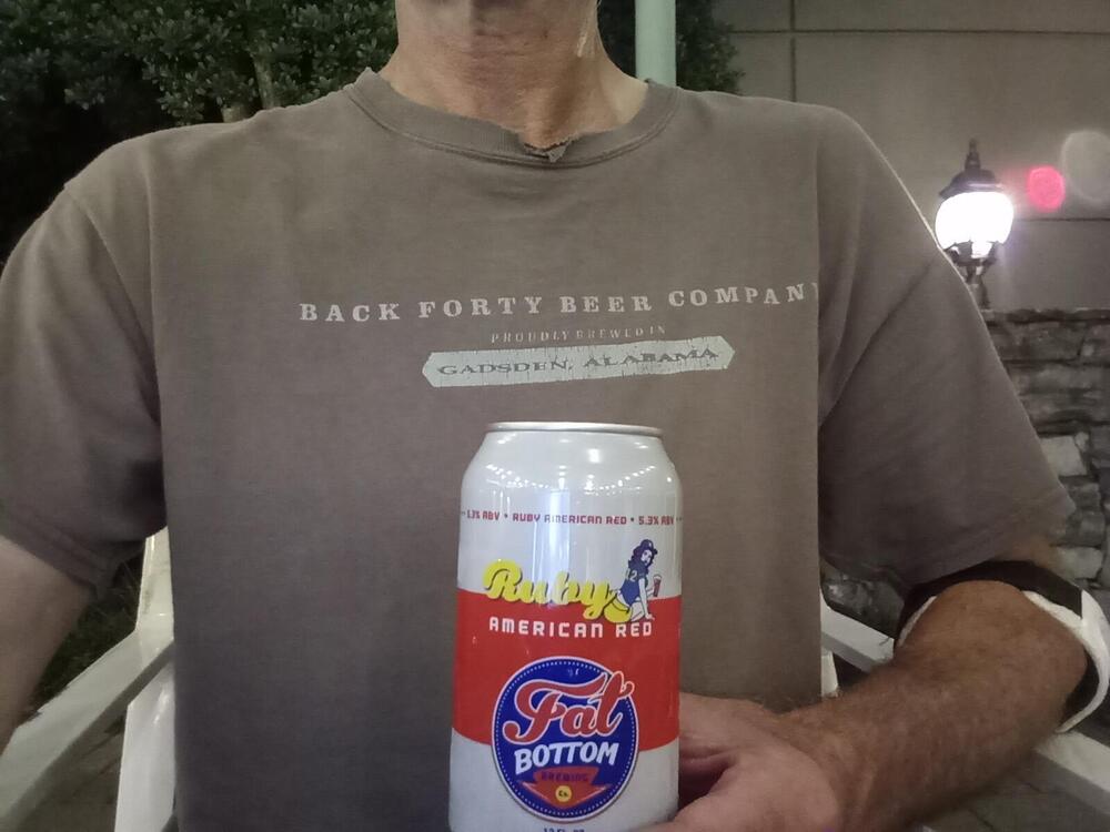
Haha!! No, but I learned a new trick... I can hot spot my phone. So I bought a tablet thing device* that can do navigation so now I can GPS on the tablet THROUGH the flip phone. That's also how I was able to take a pic of me drinking beer on the patio at the hotel at Zcon. Hot spot the phone, tablet to the web, and show off my favorite shirt while guzzling beer: *It's a phased out Lenovo thing. Cost $40 closeout. Best forty bucks I've spent in a long time.
-
Put the tube on and crank the motor over.
-
Hahahahahahaha!!!!! ☺️ That's awesome!
-
Wait... I'm supposed to have straps under the seat bottom? So THAT'S what those stiff crusty things hanging down were supposed to be!!
-
The circumference of a 185/65/14 is about 95% of the original size. So your speedo should read high by roughly 5%. The 185/70/14 I'm running are about 98% of stock and (according to GPS data) my speedo reads a little high as well. Couple mph, but nothing objectionable. Honestly after sitting for so many years, I'm actually quite surprised how accurate it really is. I would not have been surprised if it were way worse!
-
Just before the trip, I replaced all the tires. Four corners, and the spare. I got them at Firestone, but what I put on was dictated more by "what was available near the size I wanted" than anything else. The original tire size was 175 SR 14, and the web says that back then, when the aspect ratio was not spelled out, it was 78%, So using that, the original tires were 175-78-14. The closest to that size I could find near me was 185-70-14's, which is a tiny bit smaller than the original size, but only about one percent different. Close enough considering the availability. I went to Firestone and got "Suredrive Touring A/S 185/70/14" on all four corners and the spare. Nothing special, but very close to the original size. And the date codes were from late 2024 which was a whole lot fresher than the tires that were on there before.
-
If you would have asked me that question before I drove to Nashville and back, my answer would have been more definitive. Now, I'm cautious about how my back reacted to the journey. The rest of the car, however, worked great! Other than the radiator needing to be cleaned out, everything was rock solid! He drives like a dream. Starts almost instantly*, handles well, electricals were perfect day and night. Really a pleasure to drive, even at speed. But my back has me a little spooked. My 280 has different seats, and I didn't realize how much I appreciated them until I spent extended time in the OG. And putting different seats in the 240 flies in the face of the originality aspect. Haha!! Maybe I'm still stung from the road... Ask me again in a week or so. ☺️ *During the banquet, I made a comment to Madkaw about how easily the OG started, and he said he might challenge me to a "start-off" with his car. Well after seeing just how quickly and easily my car started, he withdrew the challenge. LOL!
-
Thanks for all the support guys, and never say never, but I don't think I'll be driving to Phoenix for Zcon! I'm confident I could have the radiator issues mitigated by then, but I don't think my back would make it even if the car would. Haha!! ☺️
-
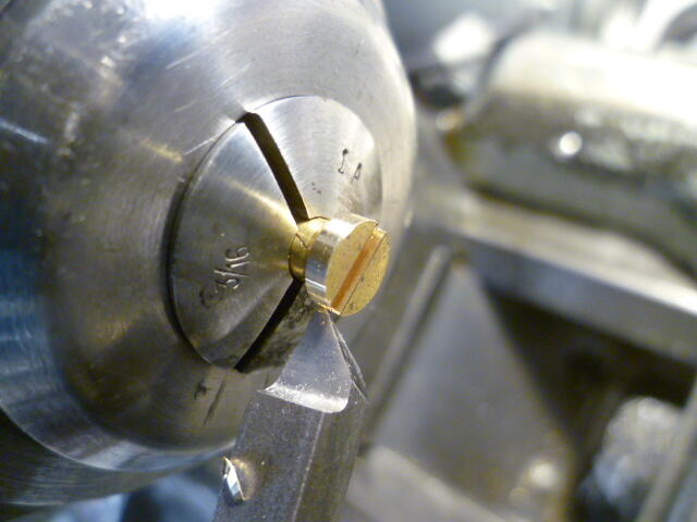
Last time I messed with this, I tried to use off the shelf screws and I could not get enough mass packed into a small enough package. I've found that 4 grams is a good amount of mass to get the float to sit level at equilibrium, and the wood screw just didn't weigh enough. Here's a failed attempt to use a brass wood screw instead of making my own weights from scratch. Pic of a wood screw chucked up in the lathe, narrowing the head, The process of narrowing the head worked fine, but the amount of mass remaining wasn't enough. I ended up making another pair of weights from scratch. Here's a pic of what didn't work out:
-
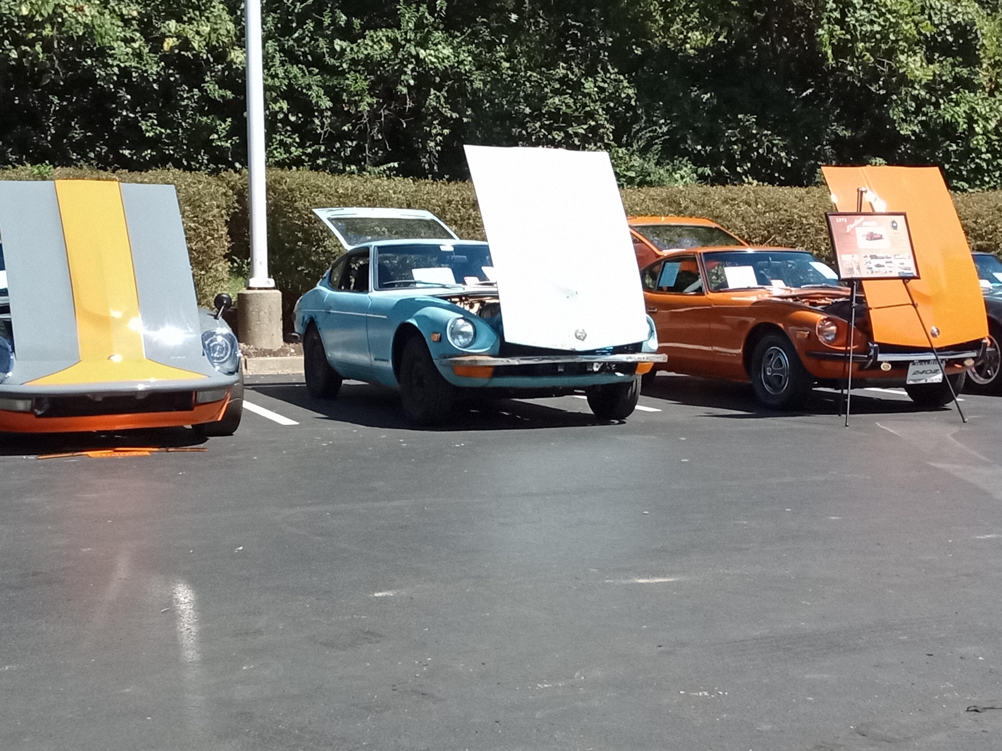
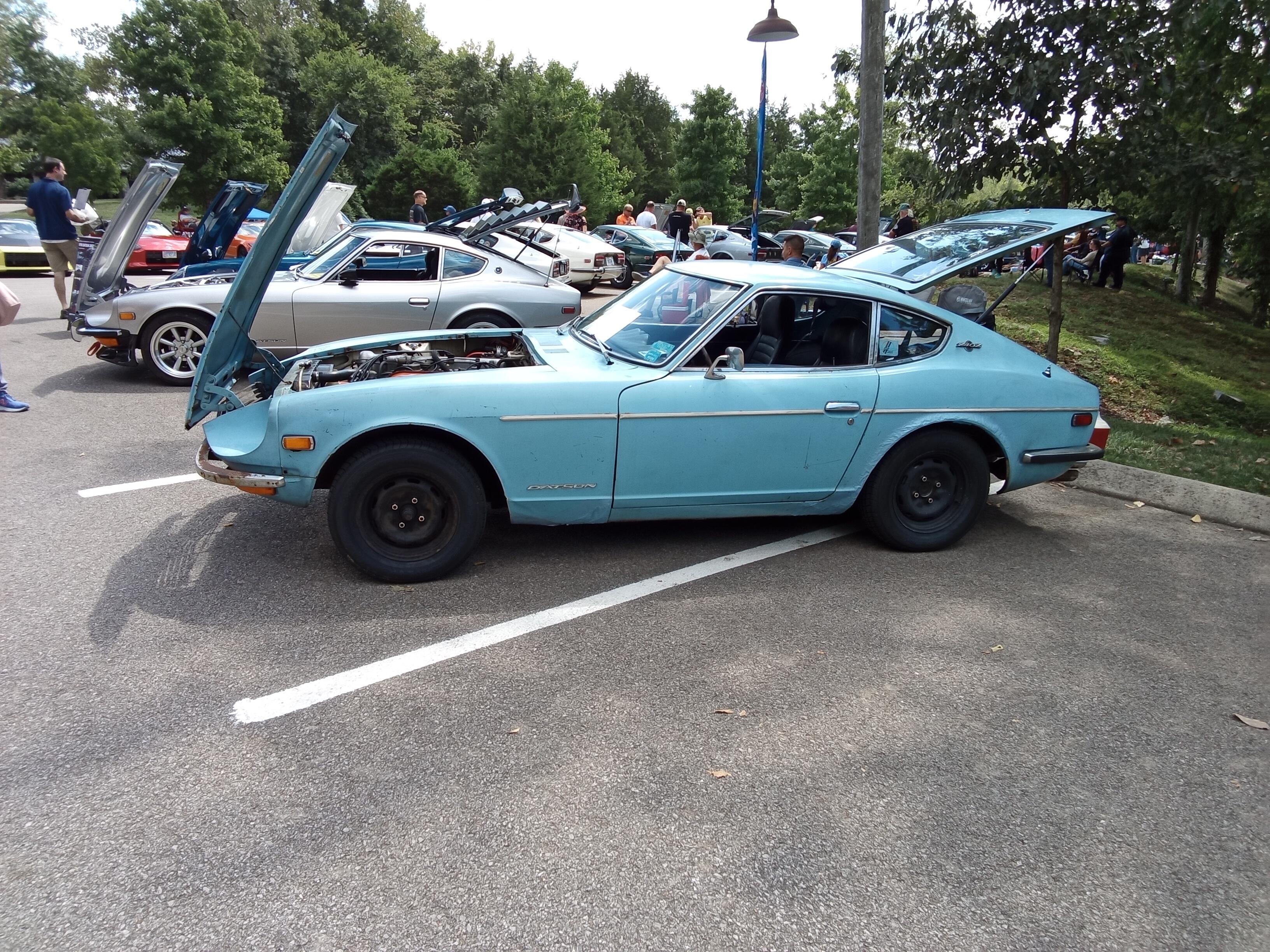
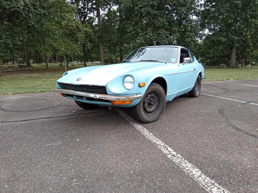
I present to you, road weary from about 2000 miles of adventure... The OG:
-
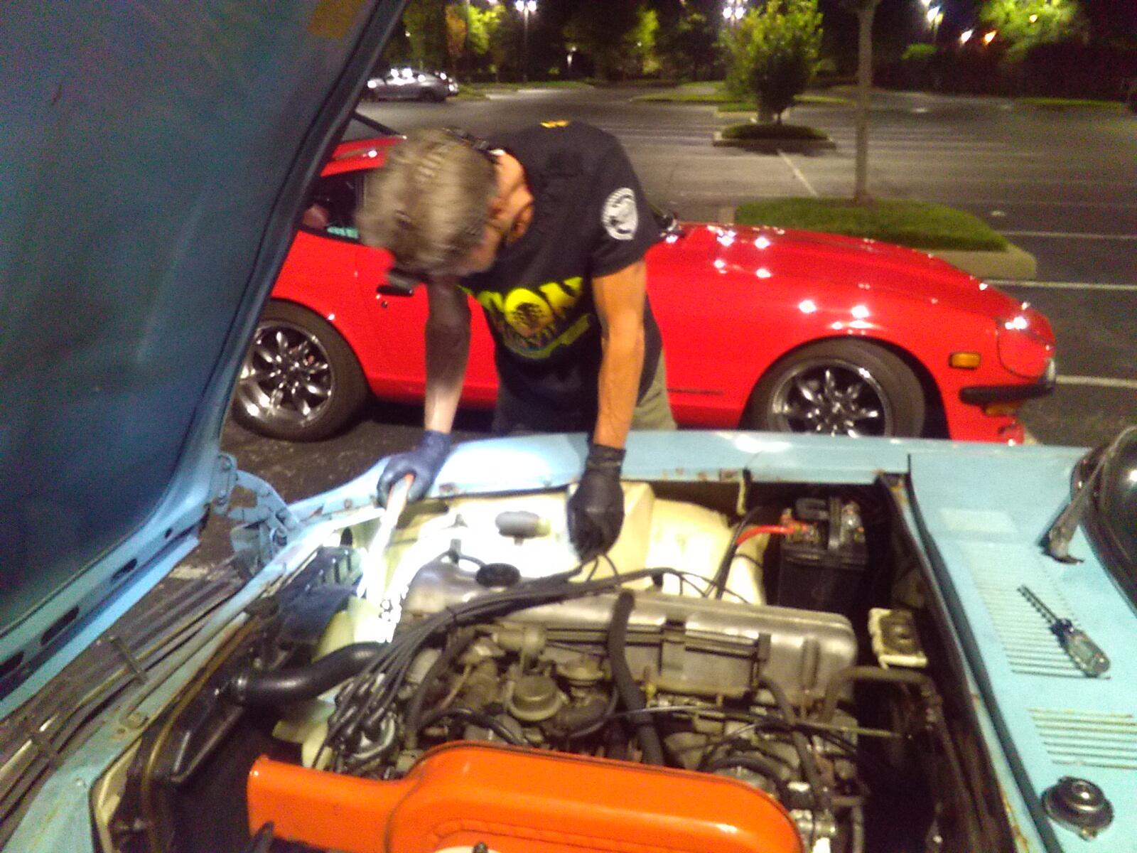
So I'm home. The bottom line is that the car fared better than I did. Remember in the beginning, I was worried about two things... My radiator and my back? Well the radiator didn't get any worse, but my back did. By halfway through the day at the people's choice show, I was hurting. I'll survive, but it's unpleasant. The radiator... I had talked to a couple people about the troubles I was having and they put it out on the Z network that I was looking for a radiator to get me home. Well as a result of that networking, there was a guy coming to the people's choice show that was going to bring me a radiator. We found eachother at the show, and I snagged a rad. He wasn't sure of the condition, but was optimistic about it. Said it looked good, and as far as he knew, it was in good shape. That night, @madkaw and I swapped radiators after the banquet. Out in the parking lot, draining the fluid, pulling mine out and tossing in the replacement. Now remember that my back is pretty much shot at this point, so when I say "we changed the radiator", I really mean "he changed the radiator". So when he wasn't looking, I snapped a pic of madkaw working on my car: Bottom line? We had to do the job twice, cause the replacement rad I got from the guy at the show leaked horribly and wouldn't hold coolant. Sigh. So, we drained again and put my original back in. It holds coolant fine, but has a couple clogged tubes. I'll just have to watch the temps on the way home and adjust my speeds and load accordingly. My original radiator works fine until I'm going up a long hill on the interstate at 70 on a hot day. Thankfully as I drove north, the ambient temps dropped some and I was much better off. By the time I got to Maryland, the temps had dropped enough that I was able to maintain 70-75 on the interstates without worry. Thanks to everyone along the way that helped with the trip and glad for the chance to meet some of the forum guys!! @madkaw @Ninjaneer11 @zed2 @Parman @inline6

-
Great meeting in person too. And agreed.. Wish we had figured it out sooner and spent more time together. See what happens when you stop hanging out here? ☺️ I've got a pic of you working on my car. I'll put it in my adventure thread. Haha!!
-
Im in good company!!

-
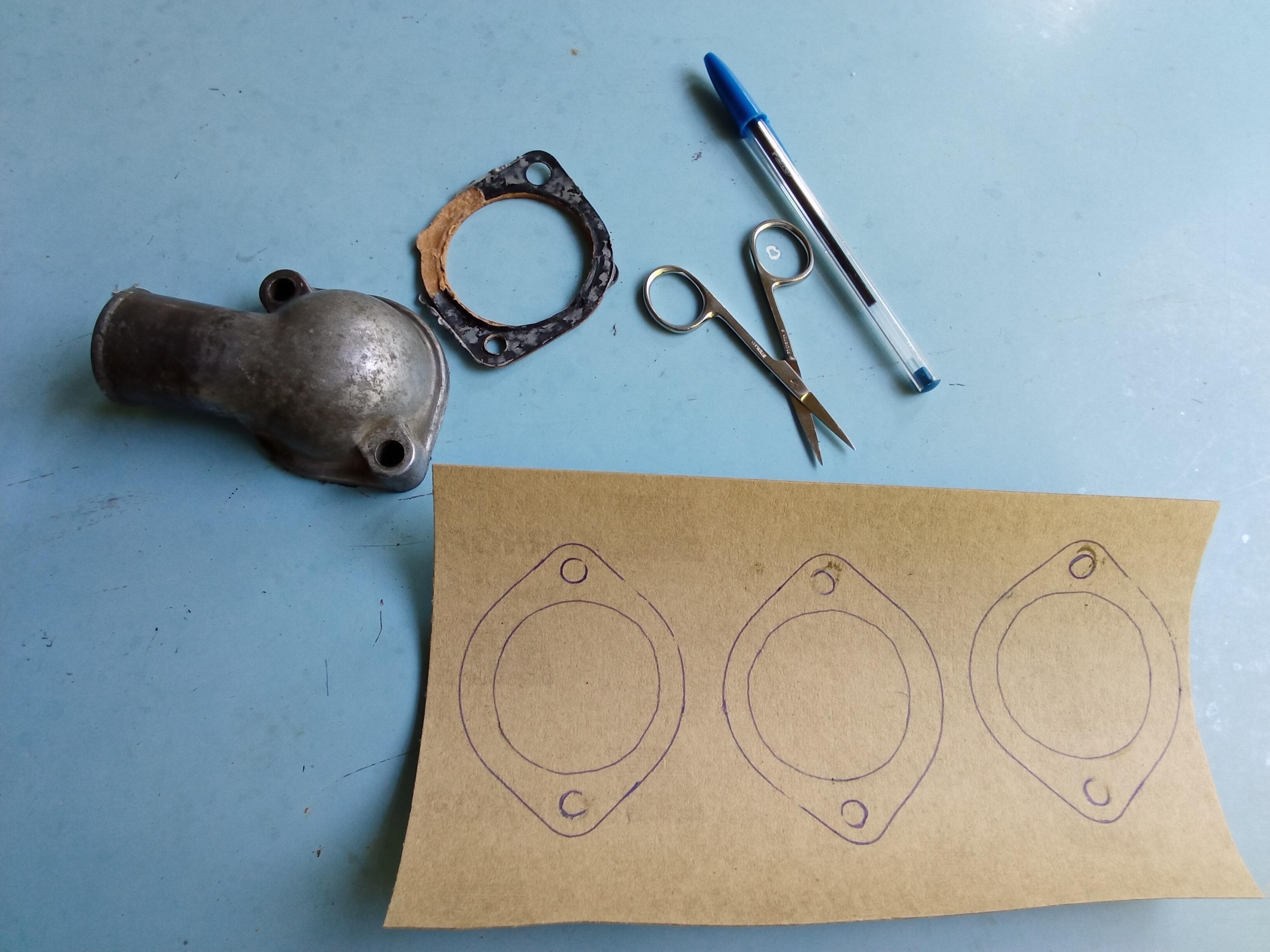
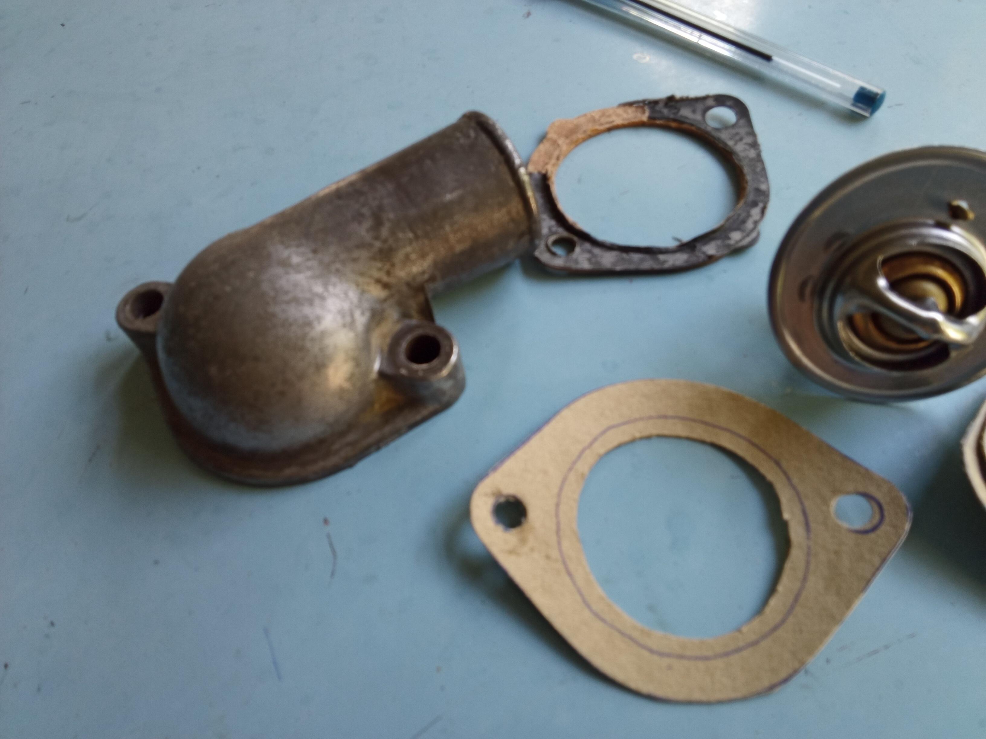
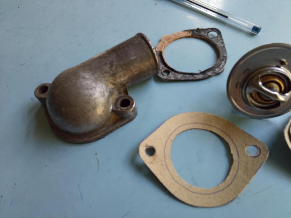
Todays event... I put a160 degree thermostat in. Didn't expect it would help anything, and it didn't. But just for completeness, I had to. So cut some gaskets from sheet with the scissors that came from the first aid kit and the hole punch borrowed from the hotel lobby desk. Haha!

-
Of course I think of you every time I wear that shirt. Wish you could have made it to the show. Miss the opportunity to share a beer with you!
-
I got no words... This is right now. Couldn't be more appropriate.

-
Thanks for the continued support guys! The car has a total of 71000 miles. And looking at the condition, it's a true 71000. So it's typical sketchy details when buying something like this used, but it appears the odometer has not rolled over. And of those miles, I've put about 1400 of them on since I got the car on the road. 400 before departing for Nashville, and about 1000 to got here.
-
Proof I made it! This is at the judged show. I wasn't ever able to register though because I think it was full. But the zcon organizers liked the car and told me to park it on the show field anyway. Im honored!!

-
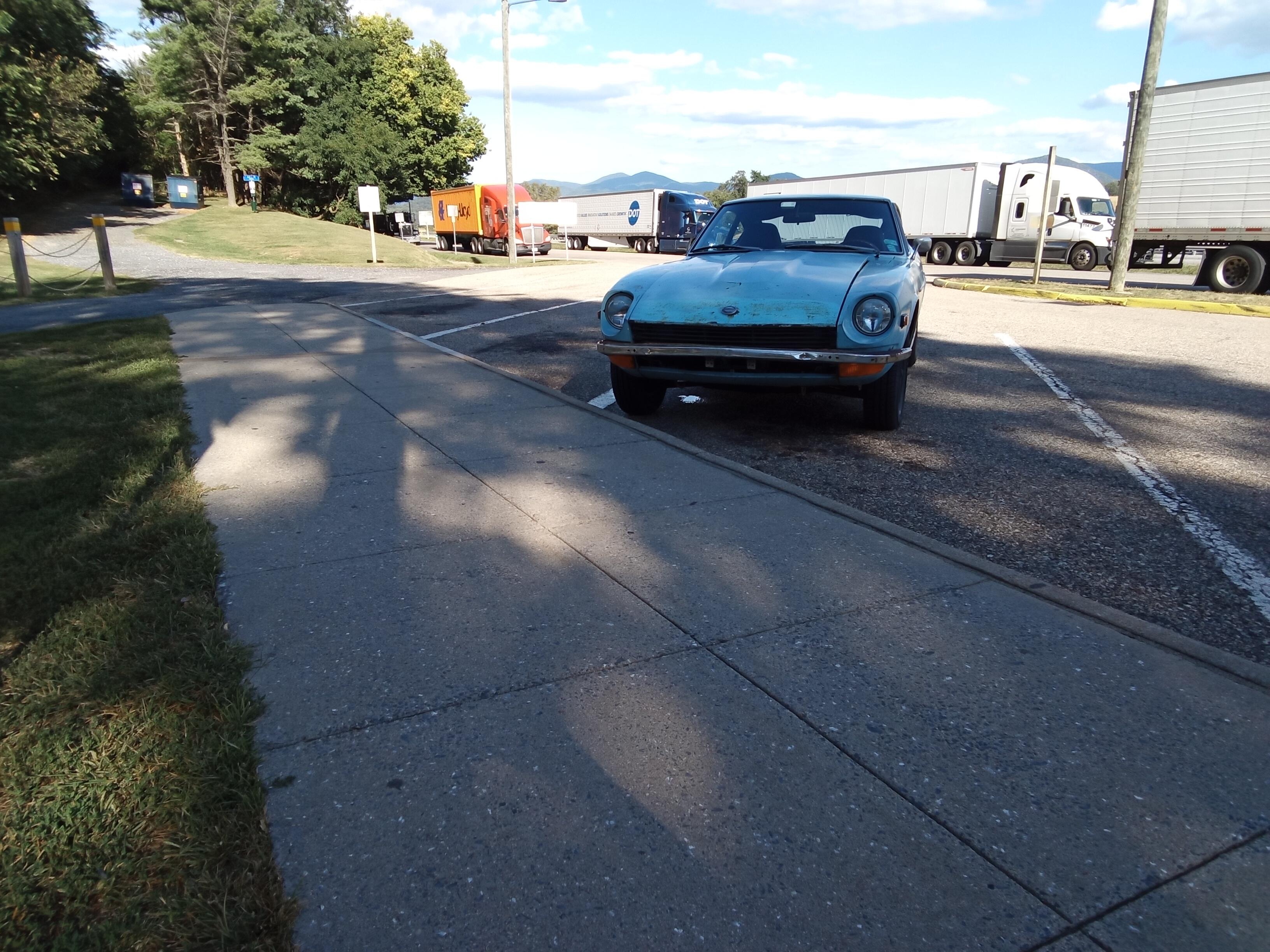
Well I made it! Got in late and just laid low. Had a beer with my local Z buddy from home. We met along the way for the last leg near Nashville. Man was that a long trip. But we made it!!!!!! I'm not sure which surprised me more with the success... Me, or the car!!😃
-
On the south side of Knoxville. Letting him cool off for a little bit. Anyone from the forum there who would like to have a beer with a weary traveler tonight?
-
So I considered registering the OG for the judged show just for entertainment value*. But I could not figure out how. I could not see any option to attend. Is that show full and they aren't accepting any more entrants? Anybody have a phone number for someone on the org committee? My electronic footprint is low while I travel, but I can text. *Him - "Dude, your car looks like asss, why are you here?" Me - Yeah, your car is beautiful, but I can see 1000 things that aren't original. And I drove mine almost 1000 miles to get here.
-
Man, I knew I needed a front bumper,but it really shows in that pic. Looks worse from a distance. Anyone near zcon got a decent bumper they would sell? Can't be too nice or it will look out of place.
-
When you are walking back to your car at a rest stop and see a puddle under it. Then you get close and realize it's just a condensate puddle from the AC of the guy in that spot before you. Phew!!