

Turn switch relay mod
Entry posted by Mikes Z car
1,734 views
Hi all,
I added relays to the turn switch to take the current load off the switch by copying the idea on the website below. The mod is reversible and by doing so will leave only hidden soldered wires inside the clamshell as the only evidence it was done unless holes were drilled to mount the relays. With this setup the heavy current still flows through the fusebox but only a small current flows through the turn switch itself. I followed this website posting but I used a different brand of relays and added a connector strip; I am grateful for the information:
240Z Turn Signal Switch Circuit Modification
The link above is to the article contributed by: Peter Paraska
As in the article I took the switch apart to scrape clean the contacts though I also sprayed all contacts with deoxit contact preserver. IMO an easy alternative to relays is to clean the contacts only and not install relays; the switch with cleaned contacts should last quite a while. I went with relays because my DD uses them, it is an 83 model and has never had a light switch problem.
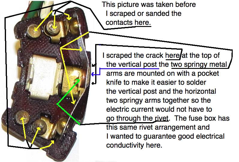
Inside the turn switch I soldered the rivet where it makes electrical connection as the fuse box uses similar rivets. This was done in case I return the circuit to stock, this soldered connection isn't used with relays:
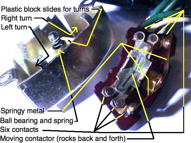
Turn signal switch in action, ball bearing not shown (click for animation):
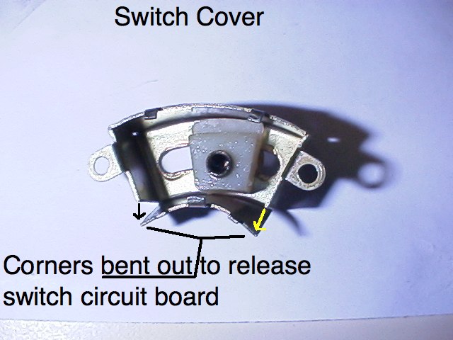
I have read that newer cars have one contact on each side of the "see saw" where my switch has two. I ran fine sandpaper through the two upright springy contacts being careful not to bend them back too far so I wouldn't permanently bend them however these two contacts are not used for heavy current with the relays installed. I had read that others had taken the similarly constructed headlight switch apart more than once and sometimes the tabs that hold the switch circuit board in place break off if they are bent too many times. To avoid that I bent the two corners of the smaller curved metal side of the turn switch cover out as the corners only have to bend at a small angle before the tab releases the switch circuit board thereby reducing metal fatigue. I used channel locks to squeeze the switch cover back together during reassembly as a parallel force in line with each side prevented twisting of the cover. Note that IMO it is easier to get the bearing back in if the switch is taken apart by bending the tabs rather than what I did as the reassembling parts approach each other straight on then.
Ball bearing:
I added a Radio Shack white strip connector to make it easy to troubleshoot/correct any wiring errors if needed. Schematic and picture of my adaption of Peter's circuit:
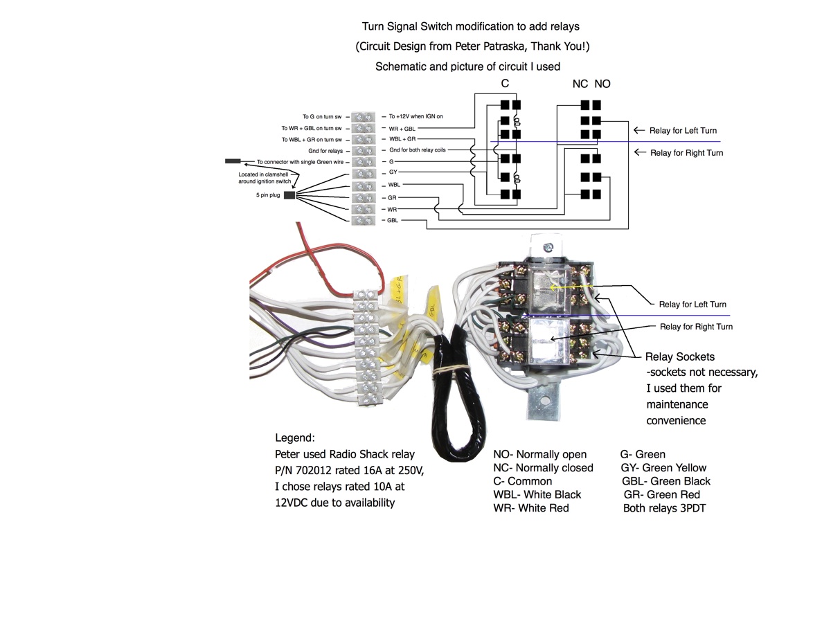
Note that on the back of my turn switch circuit board I soldered together the white Red and Green Black wires to improve reliability as this puts two contacts in parallel. If one contact should fail the other will likely still do the job. I did the same with the White Black and Green Red wires on the turn switch for the right turn relay. Newer turn signal switches have one wire where mine has these two I understand.
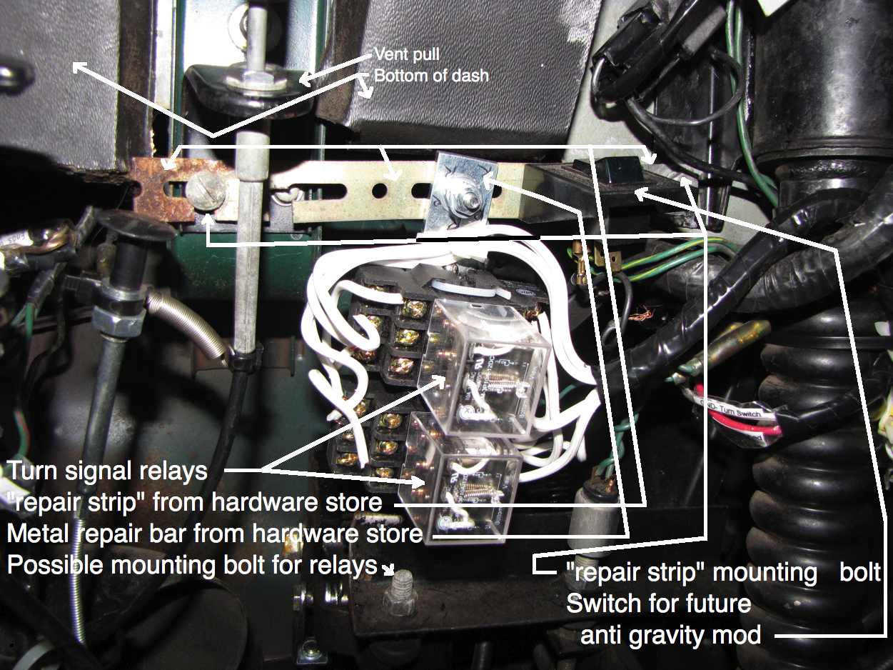
Relay mounting- works, but I may not leave it like this:
The relays I used are the same kind described in the article, two triple pole double throw relays, but they are a different brand. Peter used a radio shack relay, part number 702012. Note that a relay rated for 15A at 240VAC isn't the same as a relay rated for 15A at DC. The DC current rating is what is important here as generally relays can handle more AC current than DC. To make sure I don't forget how to revert to stock wiring I printed a copy of the schematic and the picture of the wiring layout above and taped them to the inside of the clamshell.
Mike
****************************************************
This may or may not be obvious but triple pole relays are not the only option for this mod. Other relay configurations will work depending on your creativity. One possibility would be to use 6 single pole double throw relays. Each triple pole relay could be replaced by three single pole double throw relays with the three coils wired in parallel. My feeling is that triple pole relays are easier to wire because of how I think about the wiring process but someone else might work fine with another relay configuration.


0 Comments
Recommended Comments
There are no comments to display.
Create an account or sign in to comment
You need to be a member in order to leave a comment
Create an account
Sign up for a new account in our community. It's easy!
Register a new accountSign in
Already have an account? Sign in here.
Sign In Now