.JPG.cfcada9cf1c1b502df3f5f2f2ca3ff36.JPG)

SteveJ
Free Member
-
Joined
-
Last visited
Everything posted by SteveJ
-
 Interesting concept.
 -
You could jumper off the red wire on the reverse switch. I would install a 5A inline fuse for it to make sure you don't take out other systems in the event of a short circuit.
-
Since there is no electric choke in a stock Z car, could you give us some idea of what you think is an electric choke? When you are posting for help, it is good to include information on your car such as year and modifications.
-
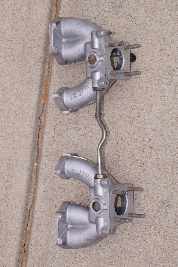
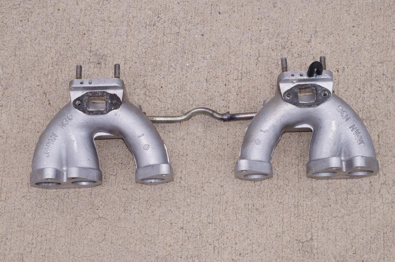
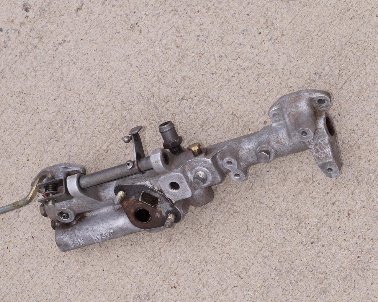
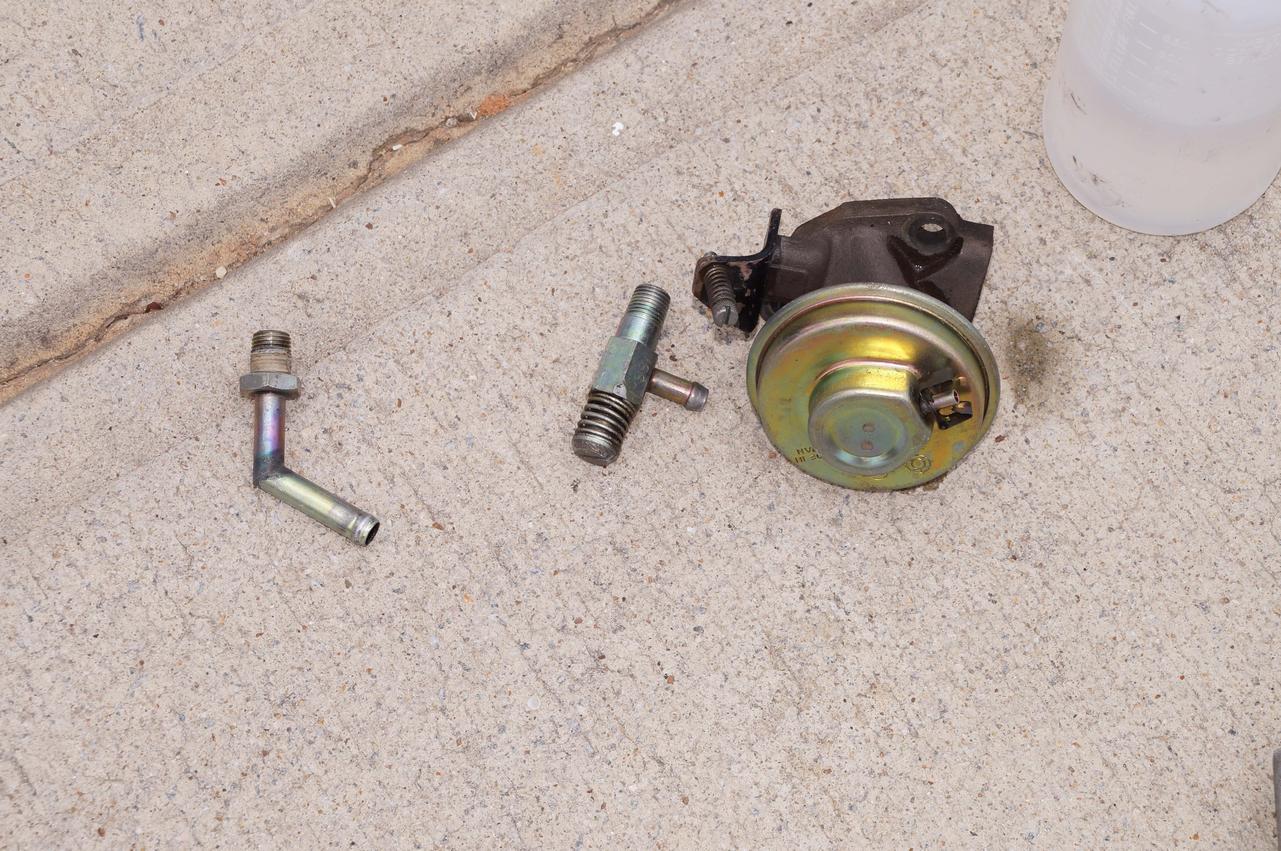
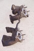
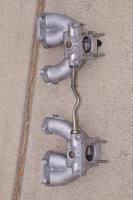
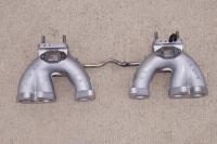
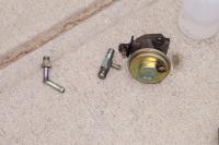
I tried my hand at cleaning up the intake. This is what it looked like before. I cleaned it with degreaser and rinsed with denatured alcohol. (If I remember my chemistry correctly, the ethyl alcohol with mix well with any remaining water and help the water evaporate.) Then I cleaned it with brake cleaner and a brass brush. I followed that with the redneck blasting cabinet and soda blasting. As Cliff mentioned, it takes a fair amount of baking soda, and it won't blast off too much. I had to scrape off some of the excess grease with a razor scraper and picks. I followed that with some more brake cleaner and steel brush. Then finished with more blasting. I use a brass wheel on the balance tube and blasted some of the other parts. I rinsed all of the parts with water and sprayed again with denatured alcohol to remove the water quickly.
-
I've used up my "while I'm at it budget."
-
I already have an MSA coated 6 to 1 waiting to go in.
-
Don't be too surprised. I am going to try the SUs on the 260Z when I put it back together.
-
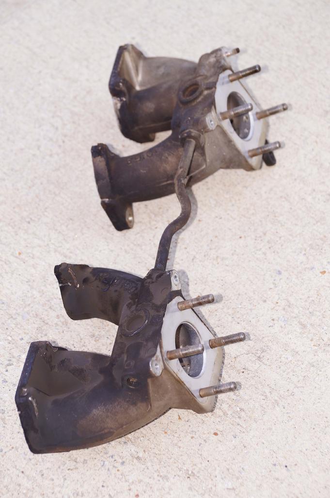
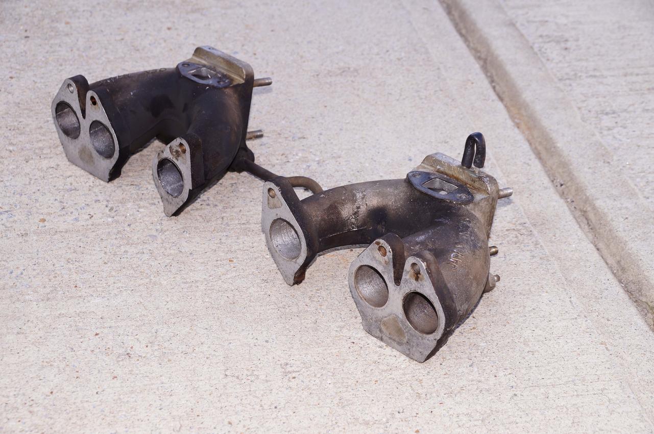
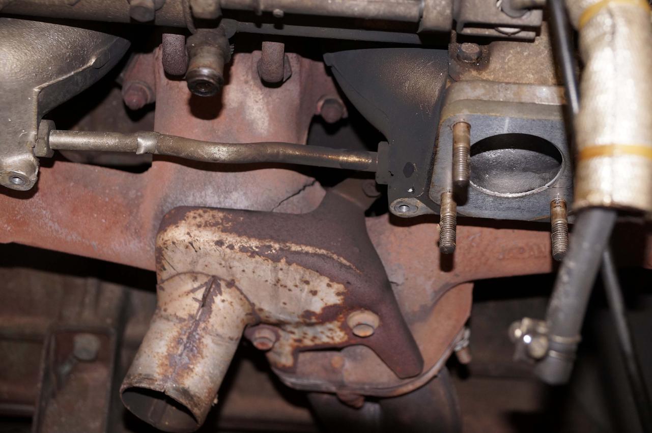
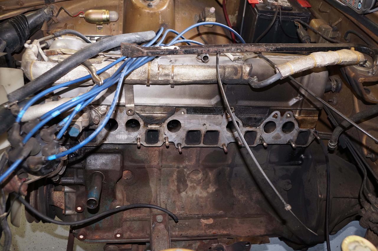
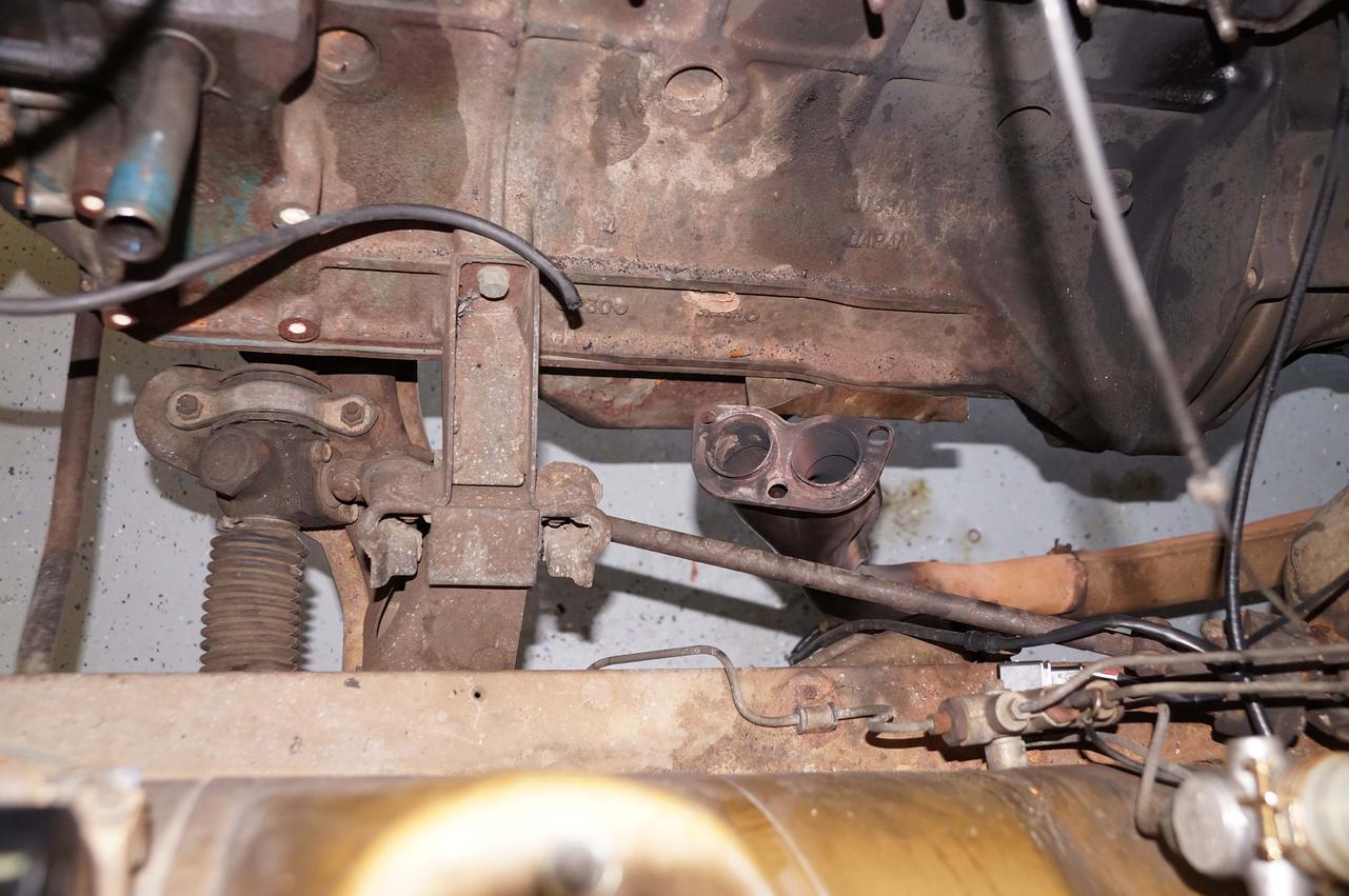
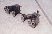
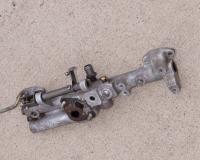
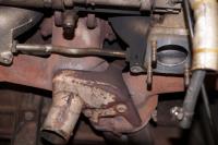
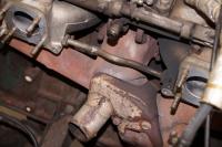
I pulled off the intake and exhaust on the 260Z today. After I pulled off the carburetors, I noticed this... I knew I had an exhaust leak. I just didn't know the manifold was trying to snap in half. I took my time and got the intake and exhaust taken off. The flash of the camera really emphasizes the magnitude of the leak. After that I got the materials to make my redneck soda blasting cabinet. I'll let you guys know how it works out.


-
-
-
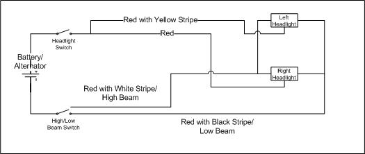
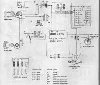
If your wiring is stock, here is how the circuit goes: 1. From the positive terminal, the circuit goes through the fusible link and up to the white/red wire and on to the combo switch. 2. When the switch is on the headlight position, the circuit is closed to the red wire that goes down to the fuse box. 3. At the fuse box, the red wire splits to the left and right fuses where it comes out as red/yellow (left) and red (right) and goes out to the headlights. 4. The circuits go through the headlights and come out as red/white (high) and red/black (low). The wires from the headlights merge and go back to the turn signal side of the switch. 5. The high/low beam switch will change which wire (r/b or r/w) is in contact with ground. The FSM has a clear diagram on page BE-9 So if your low beams are not working, it is likely that there is a problem on the turn signal side of the switch. Moving the high/low beam switch will not affect the connection between the white/red and red wires. You may be using poor technique to measure voltage.
-
Matt, before you pay $9 for 10, look at this thread: http://www.classiczcars.com/forums/interior-s30/42851-fasteners-trim-panels.html And they are still available: 50 FORD FENDER SHIELD PUSH TYPE RETAINERS OEM 387843-S on eBay!
-
Not easily. The sending unit changes resistance according to temperature. The thermostat for the fans is more of an on/off switch. If you did manage to find a way, it would probably adversely affect the reading on the temperature gauge.
-
I don't think the 9V battery will have enough energy to drive the ammeter enough to tell you anything useful. Also, if you wire it wrong, you could damage the meter. For the fuel gauge, you would hook up the positive of the battery to the positive side of the gauge. From the gauge, one wire would go to the negative side of the battery, and another wire would go from the sender side of the gauge to a potentiometer and on to the negative of the battery. You would vary the resistance to see if the needle deflects. As for the value of the potentiometer, you would have to search through the FSM to see the resistance range for the sending unit in the fuel tank.
-
Actually there is a Ford fender retainer that is available on ebay for about $13 for 50. It's VERY difficult to tell them apart.
-
I like the looks of it. It certainly eliminates the look of a kludge factor.
-
And Matt, if you need replacement retainers, I have a bunch.
-
Matt, are you pushing the pins through first? Stock retainers have a pin going through them.
-
Did you use a conductive material between the HEI and metal plate to act as a heat sink?
-
The TIU case would provide a nice heat sink for the HEI.
-
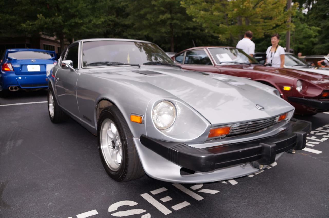
It was another Caffeine & Octane day. There were almost as many S130s as S30s today. Among the highlights for Z cars was a black pearl with original paint. It shined up nicely, too. Steve's CARtography | Combining a love of cars and photography


-
You noticed that, too? I know the HEI would work with the ZX, but I didn't want to go into all of the permutations given the OP's lack of experience. I would just suggest swapping in a new ignition module at that point.
-
The TIU is on the passenger side footwell. The picture you posted is part of your AFM. Please post a picture of your distributor before you go the HEI route. Many owners have swapped in a ZX distributor. That has the ignition module mounted on the distributor. If a previous owner did that to your car, the HEI is superfluous.
-
You only get 8 V because the circuit goes through the ballast resistor as I said in post #4.
-
When the clip is in place, you cannot see the slot. It still fits snug, and you still need pliers to pull it off.