.JPG.cfcada9cf1c1b502df3f5f2f2ca3ff36.JPG)

SteveJ
Free Member
-
Joined
-
Last visited
Everything posted by SteveJ
-
 Before I shot the video I linked, my car was running fine. For whatever reason, when I flooded the car that's when the distributor decided to act up. I replaced the distributor, and the car has been just fine since. That's not what usually happens, but apparently, it can happen.
 -
Place the end of the spark plug wire near one of the studs at the shock tower. Watch the video I made about a year ago. It turned out there was a lot of wobble in the shaft, causing poor sparking. You expect a larger voltage drop during starting because the draw of the starter drops the voltage. For reference, on a good sized CAT generator with a 24VDC starting system, you can see the voltage dropping down to about 8 volts on starting. Of course that's an extreme example because the CAT 3516 is a 69 Liter diesel engine, so the starter is fighting against a lot of compression. However, the principle is the same.
-
Well, at least the voltages are looking like you should be able to run. Are you sure you have fuel at the carburetors? Have you tried starting fluid? Can you make a video of the spark? (I did that once to figure out that I had a wonky distributor.)
-
Cliff, I can't attest to @jonbill's setup, but for many of these lifts, there are rubber or high density foam blocks that are used. You can see them in this picture. Mine also came with adapters with arms for trucks.
-
Here's a list at Northern Tool. They aren't in Canada, but you could see if someone near you carries one of these lines: https://www.northerntool.com/shop/tools/category_automotive+automotive-lifts+scissor-lifts
-
Advantages of a scissor lift: Very sturdy. It's great for wheel/hub work including brake jobs. Can lift higher than a QJ. (I also have a QJ 5000) Less guessing about jackpoints than a 2-post. I used 2-post lifts often when I was in the Air Force. The thing I miss most about the military is the Auto Hobby Shop. Disadvantages of a scissor lift: Sits high. I have the car on 2x12s over the lift so the exhaust doesn't hit. Most are difficult to do centerline/transmission work. I did replace the driveshaft with the car on the scissor lift, but draining/refilling the transmission was a pain since I had to lie on one of the bottom crossmembers. The crossmembers can get in the way of simple things like placing your catch pan under the car for an oil change. Just one thing, if the scissor lift does not have locking points as you lift, you do NOT want it. A safe lift should have locks that require the operator to disengage prior to lowering.
-
Maybe you should turn up your references to 11, when you need that little...you know.
-
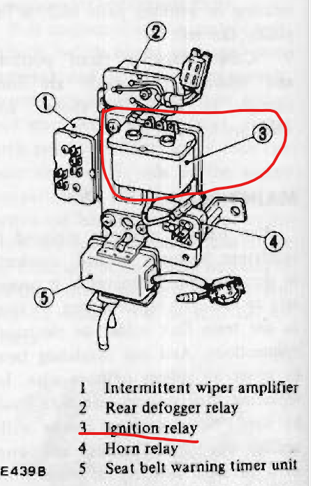
Cut down some of the wiring you're trying to trace. Pull the ignition relay. It's around the passenger kick panel Put in another 30A fuse. Turn the key to ON. See if you smoke the fuse again. If not, get with me on tracing down the short downstream of the relay.

-
This video showed up in my YouTube feed. I can see a variation of this working to fill the differential or transmission while under the car.
-
If it gets to working on the switch, this thread may help:
-
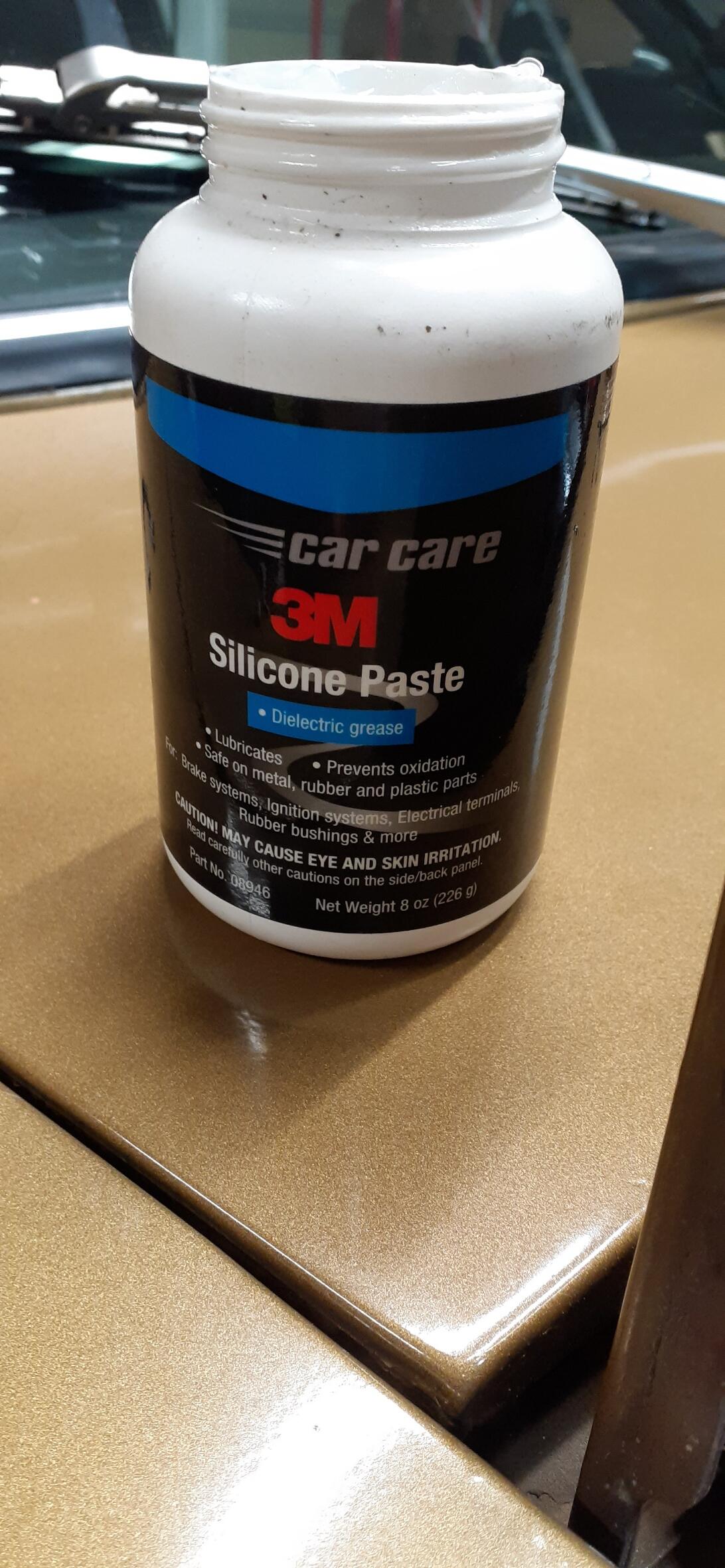
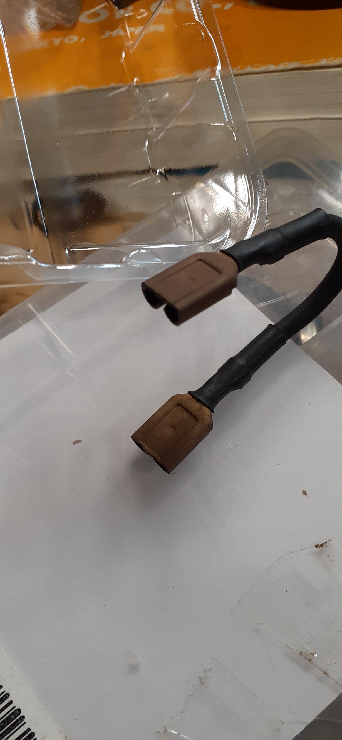
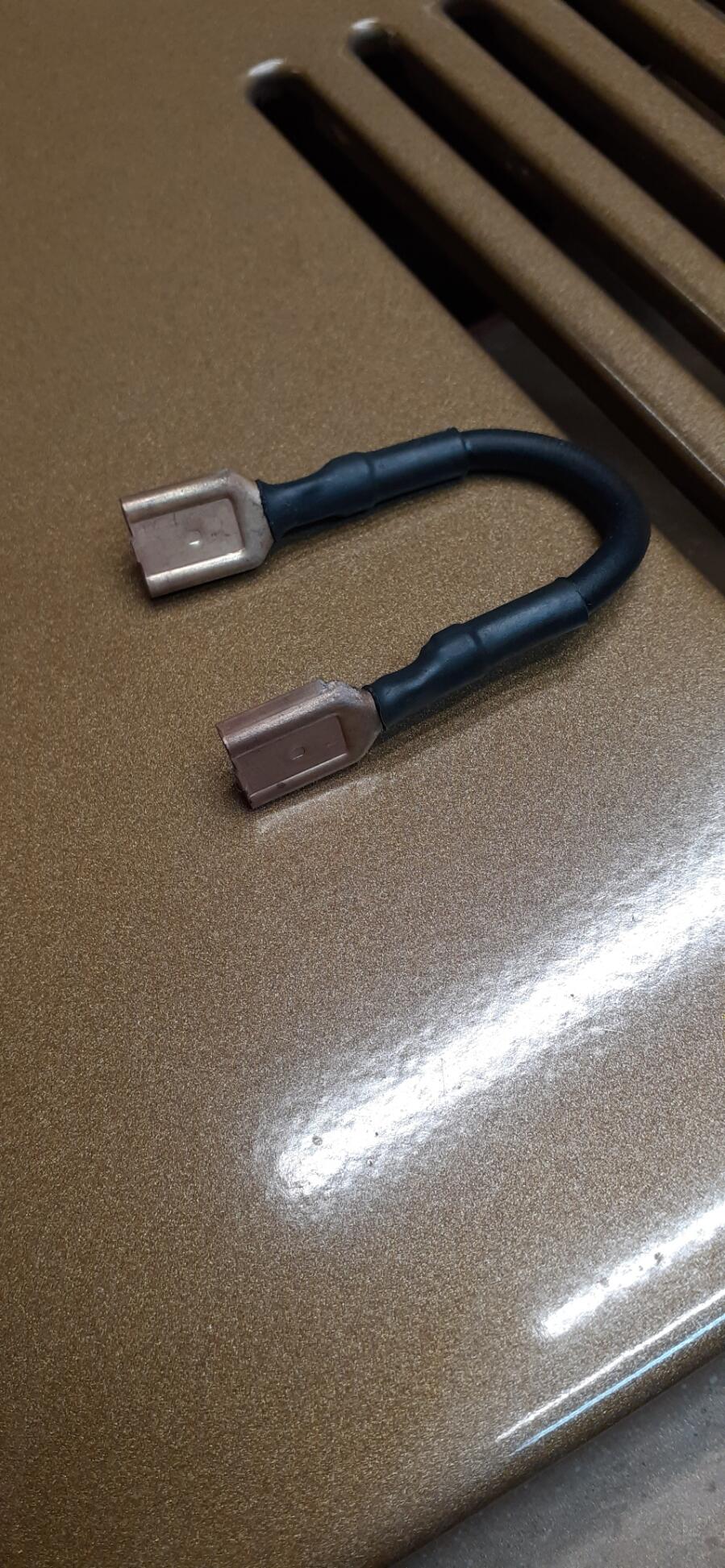
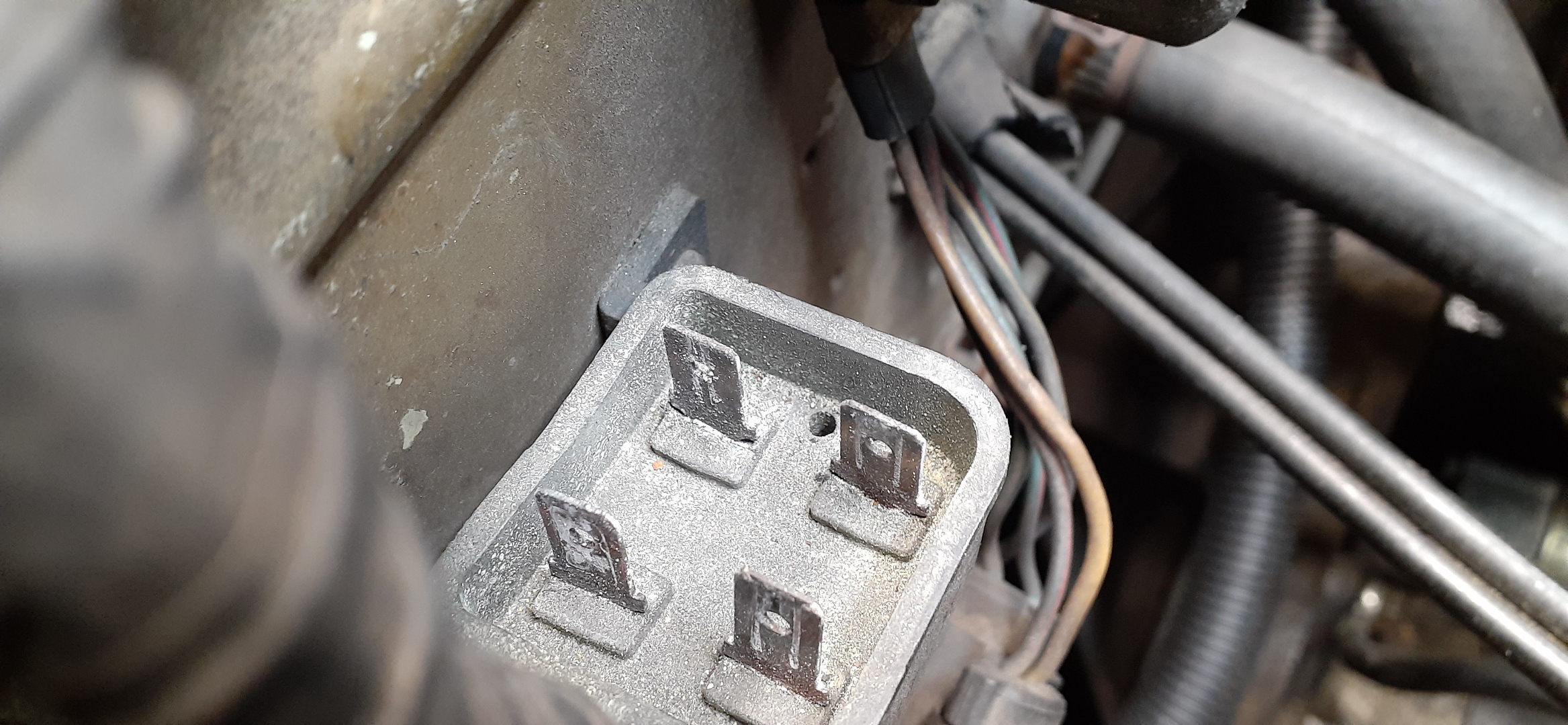
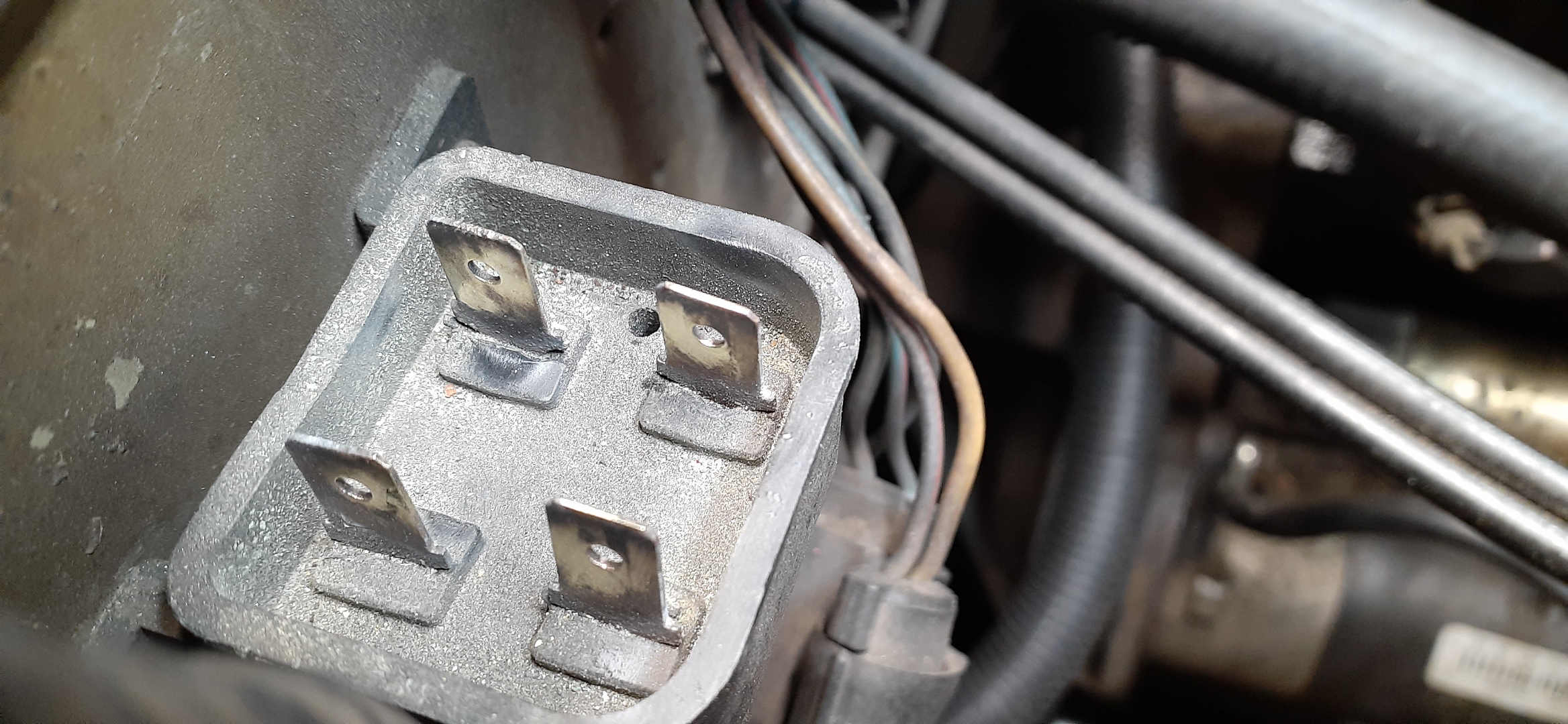
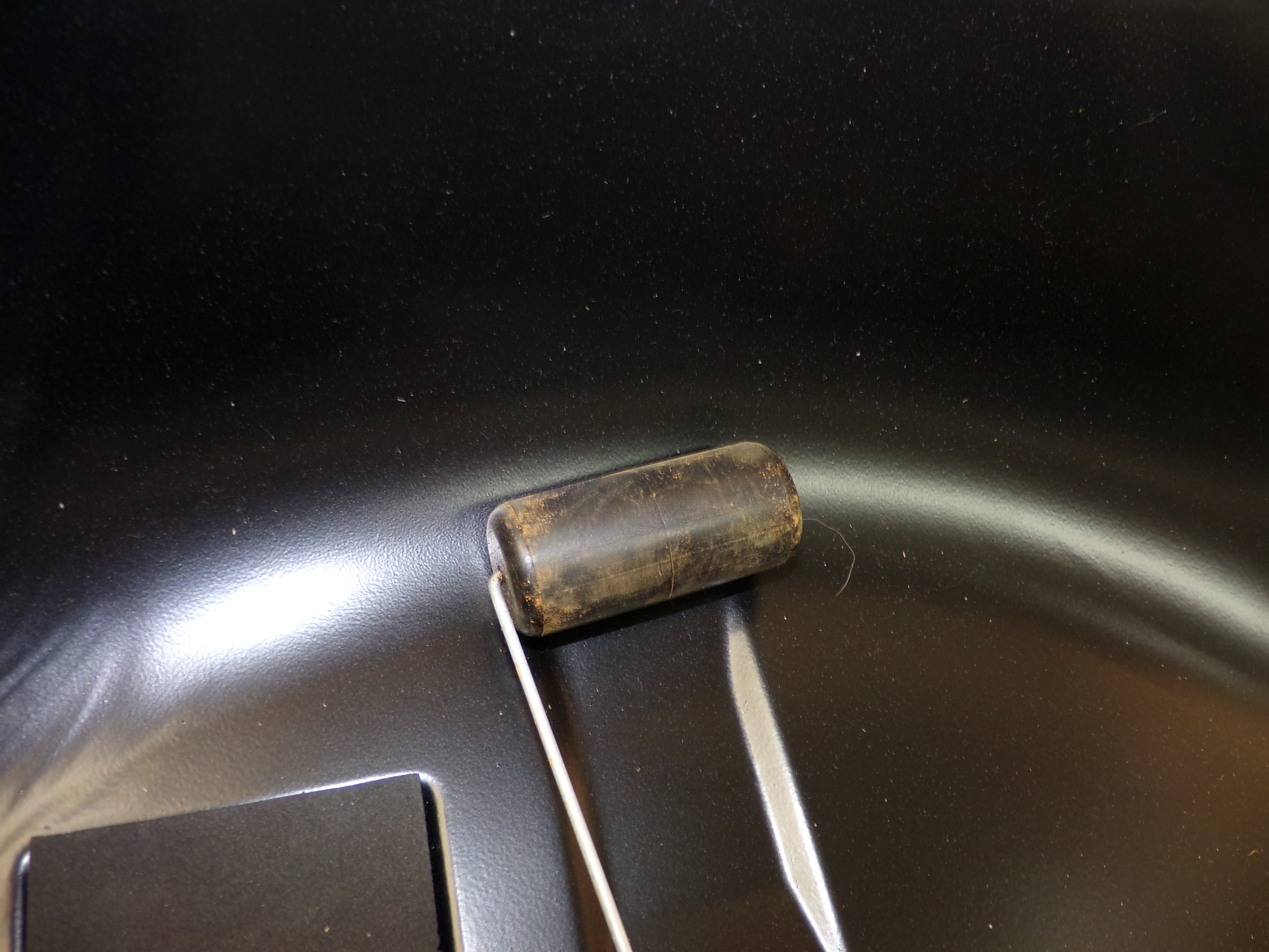
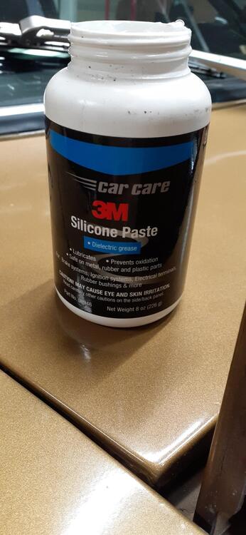
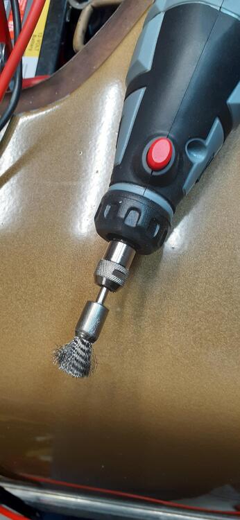
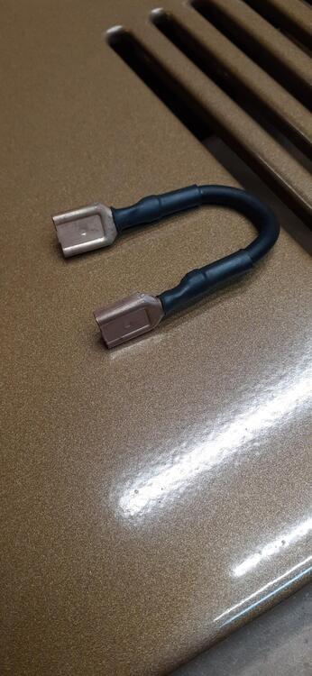
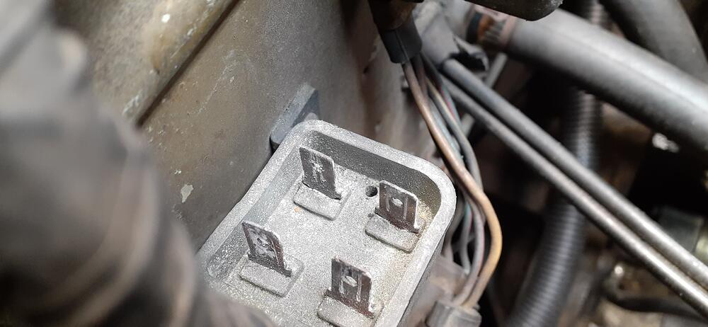
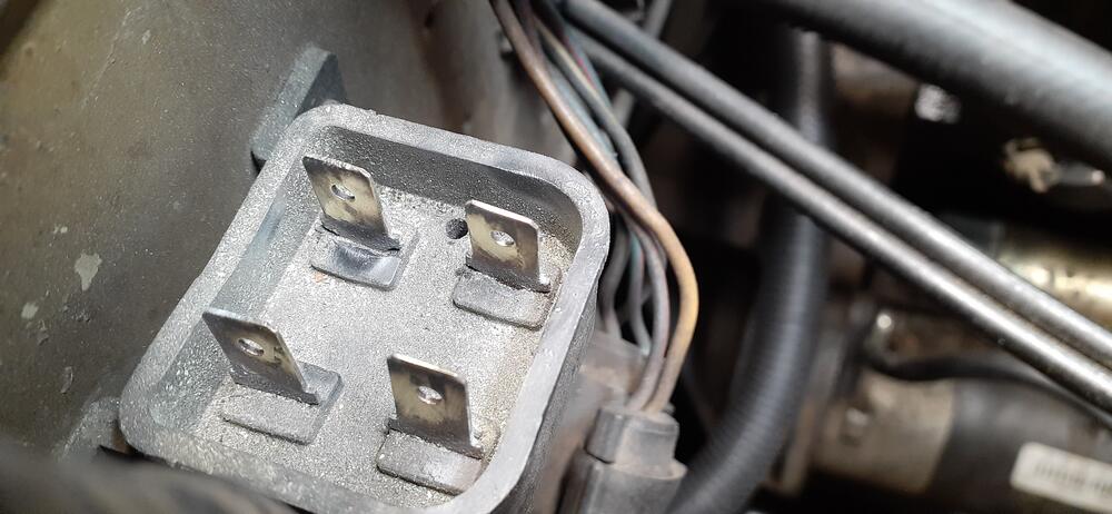
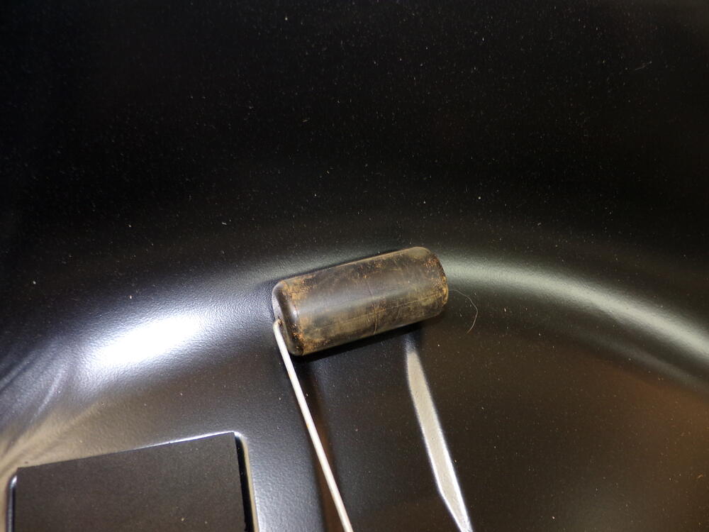
Get some Tarn-X, dielectric grease, rotary tool (Dremel) with a small wire cup brush. Here is a fusible link I replaced many years ago. I put it in some Tarn-X for less than a minute, rinsed, and beat the water out. Here is how the fusible link box looked when I took off the links. Here's how it looked after some work with the wire brush. I coated the terminals with dielectric grease and replaced the links. Try that, and re-test.

-
Here is some recent action from this past weekend at Laguna Seca: Saturday: Sunday:
-
I had a slave cylinder hose get blocked up, but that was from years of brake fluid sitting in it.
-
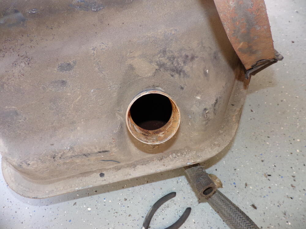
I was thinking of trying something different on the old tank. I was thinking of buying this stuff: https://www.amazon.com/dp/B0031HQJWW I'd mix it up in the tank and let it sit for a week or two since it's cold right now. After that I would dump it out and rinse the tank with denatured alcohol. After that dried, I could do some Redkote or similar product. Even if I wait to coat the inside, I could use some fogging oil to keep it from rusting. That would just require a soapy rinse afterward and denatured alcohol to give a good surface for the coating material.
-
There are two things that could cause the voltage drop If the starter is turning and the battery is not good, you could see that kind of voltage drop. There is corrosion between the battery and the ignition switch. From the battery positive, you have a cable going to the starter. It goes out of the starter to a white wire to the fusible link and comes out of the fusible link as a white wire. There it goes through the shunt (for the ammeter) and comes out white/red. The white/red wire goes to the fusible link and comes out as white/red, going to C-5. From C-5 it goes down to the ignition switch. Lots of connections to get corroded. It measures fine with everything off, but when you try to power other things, the corrosion could limit the current flow and drop the voltage downstream.
-
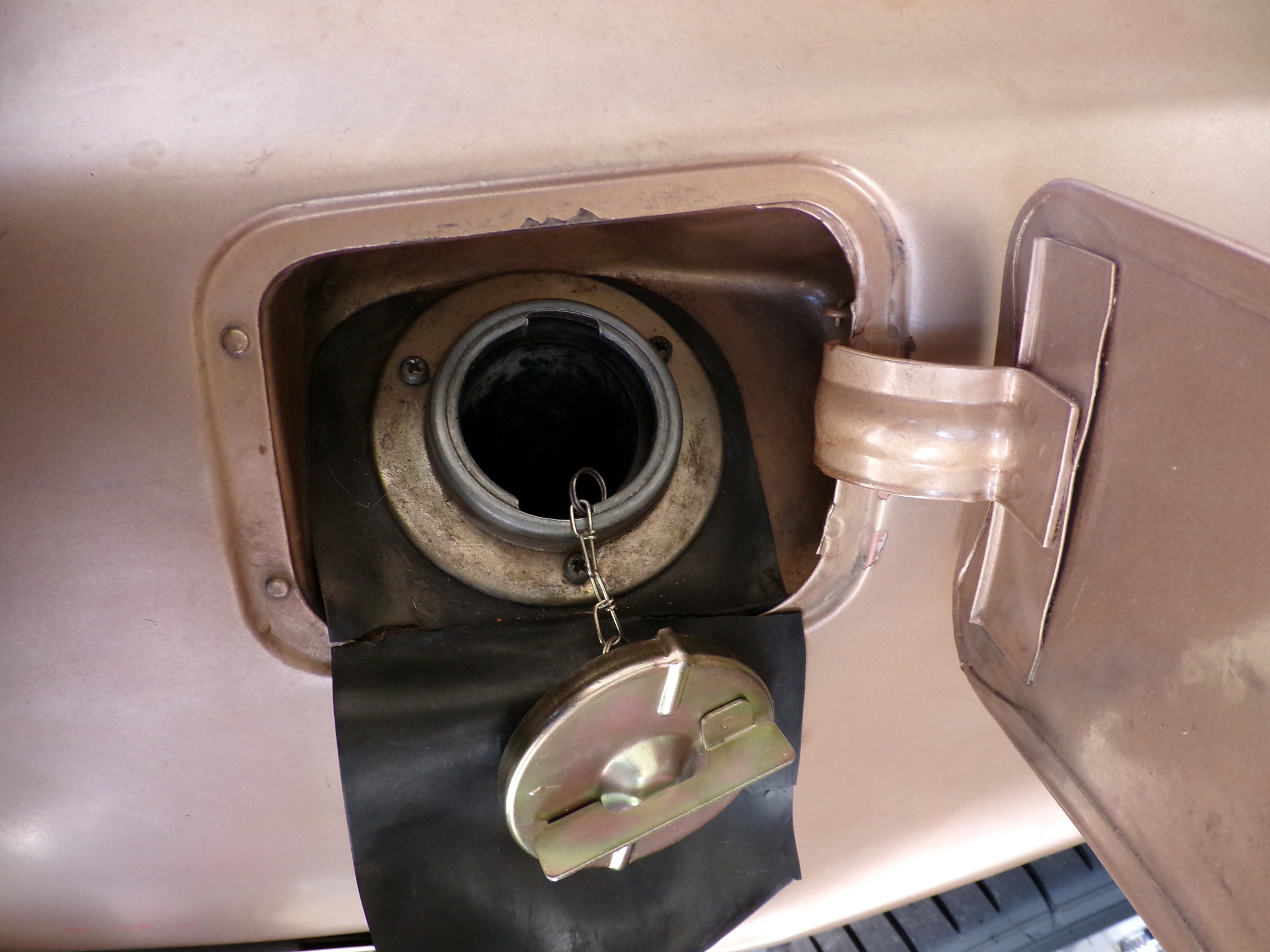
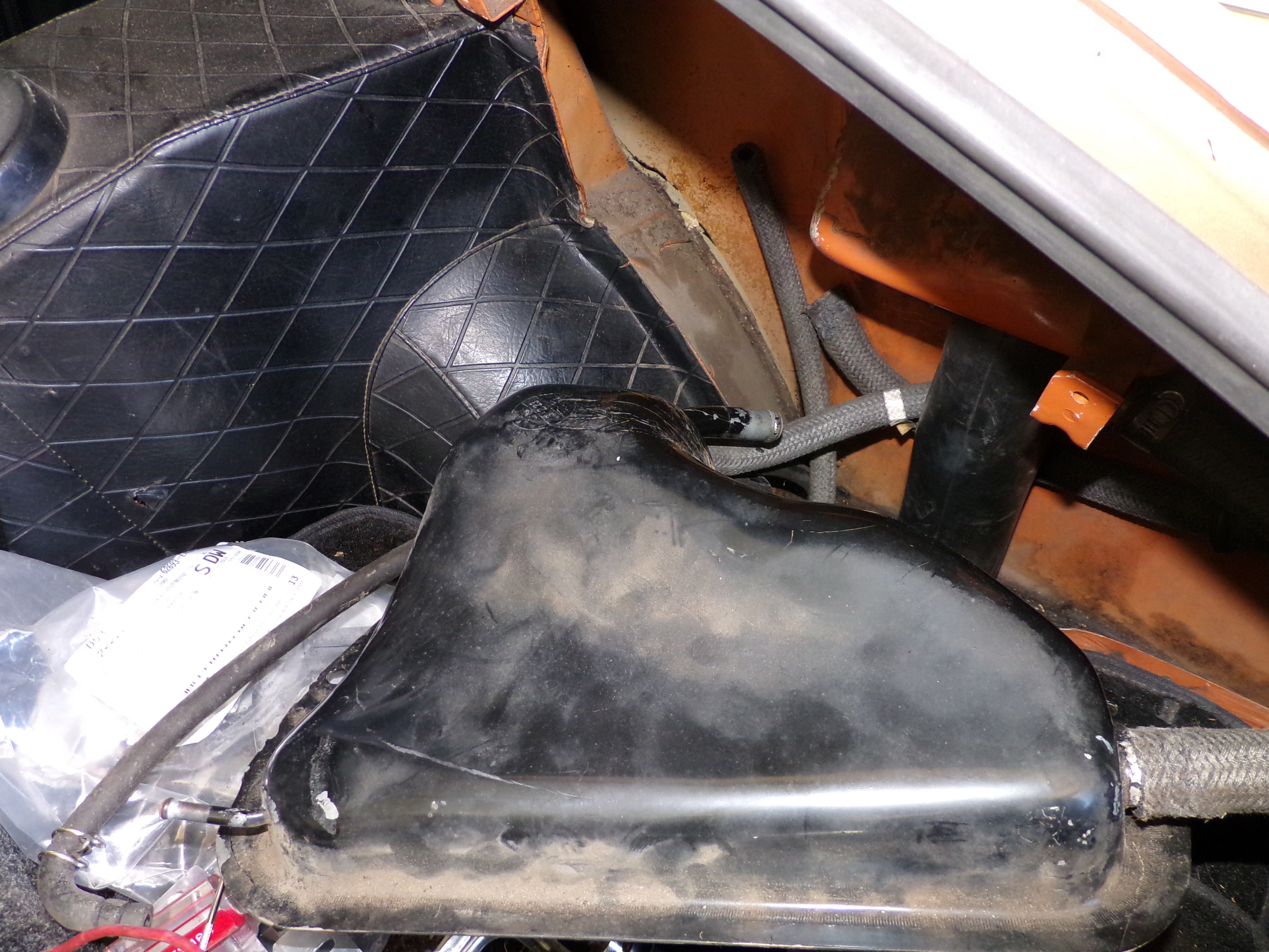
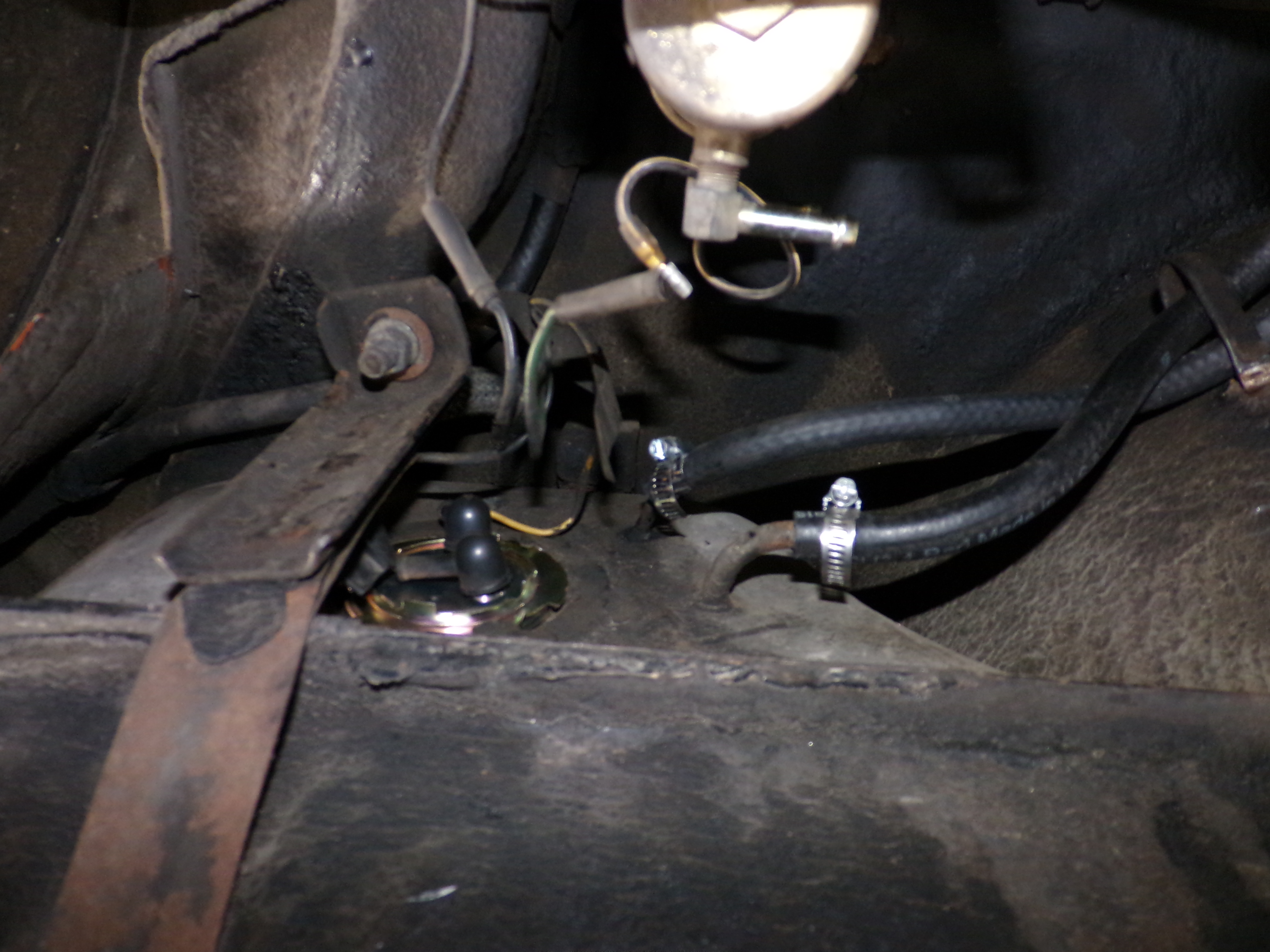
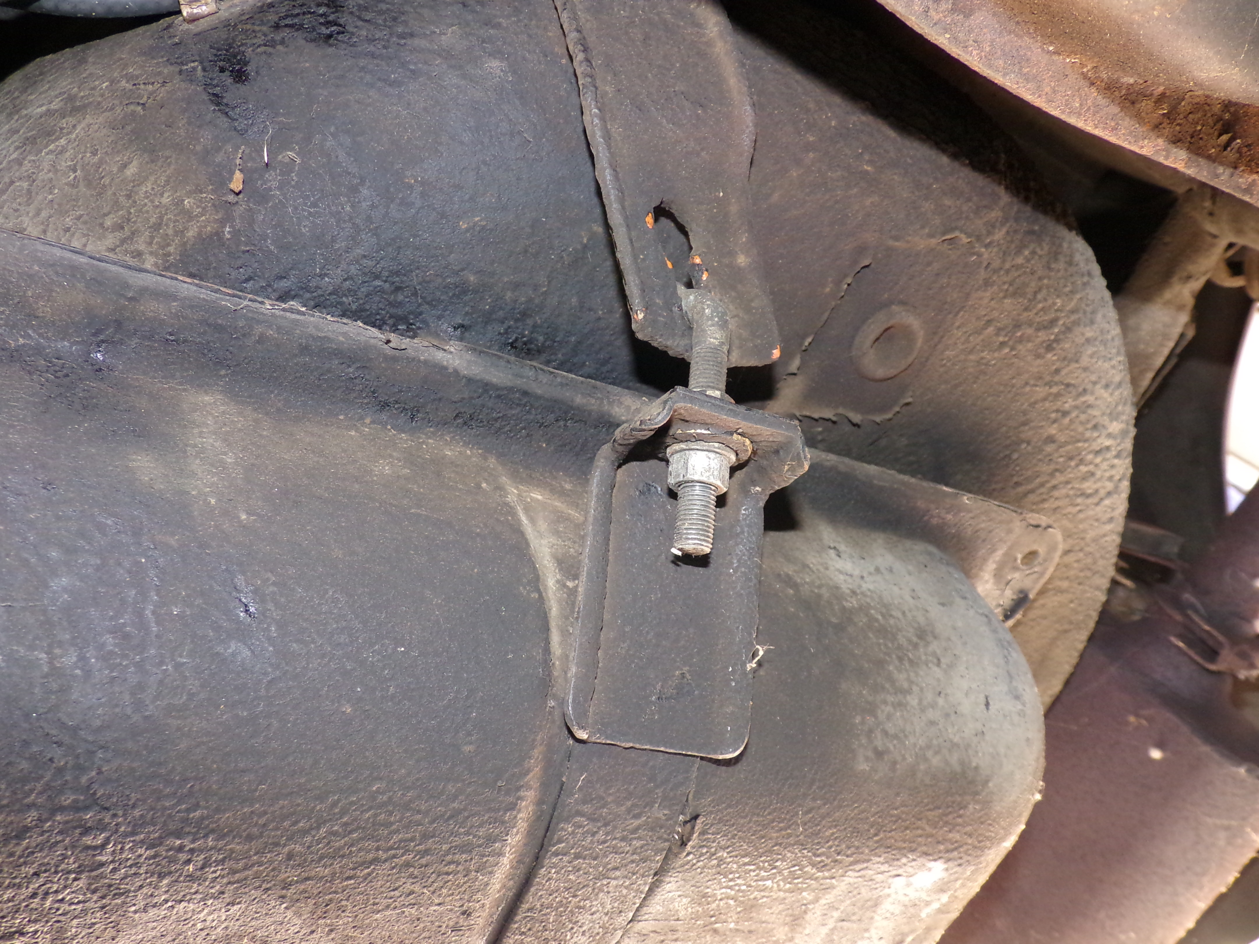
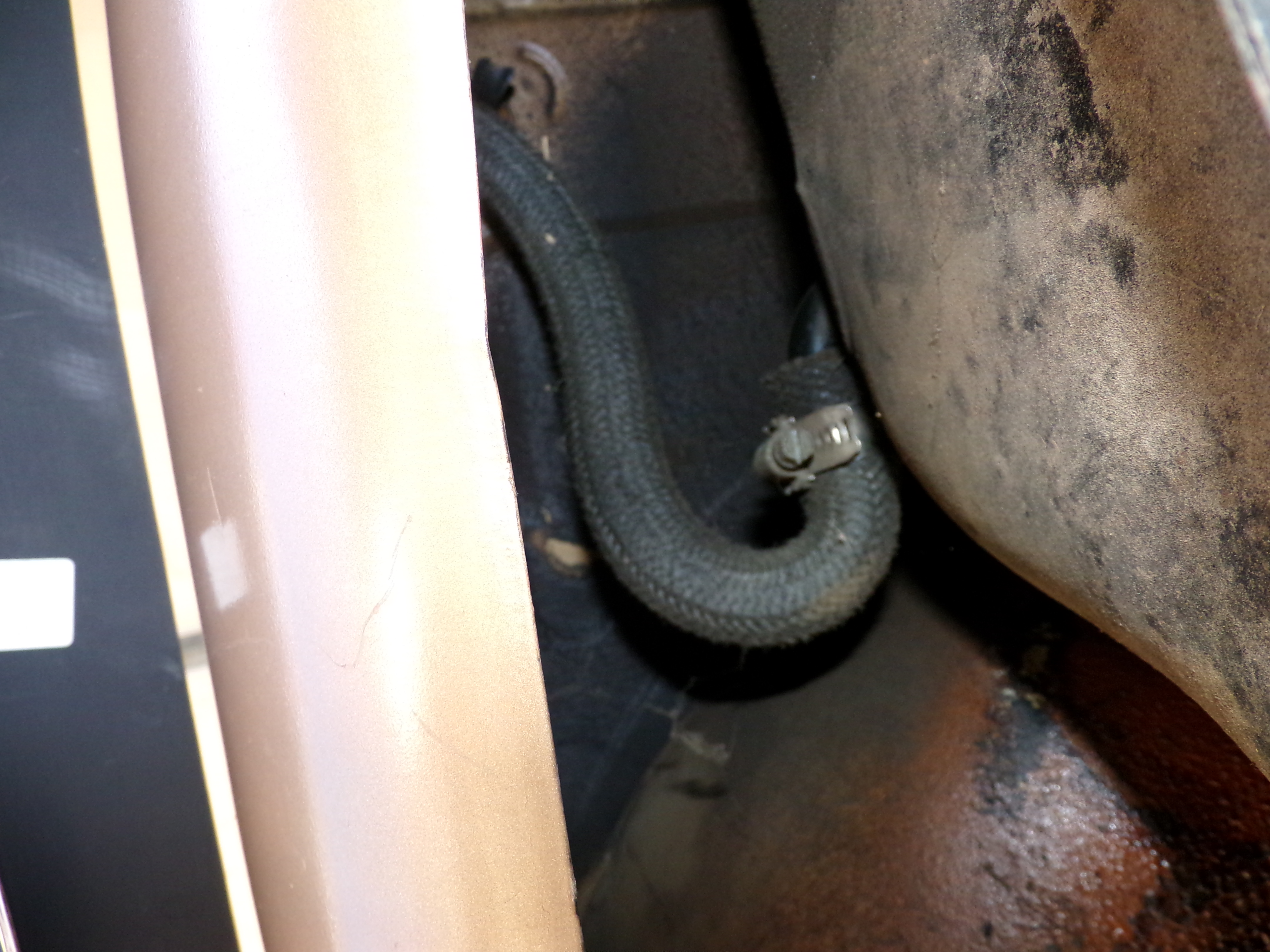
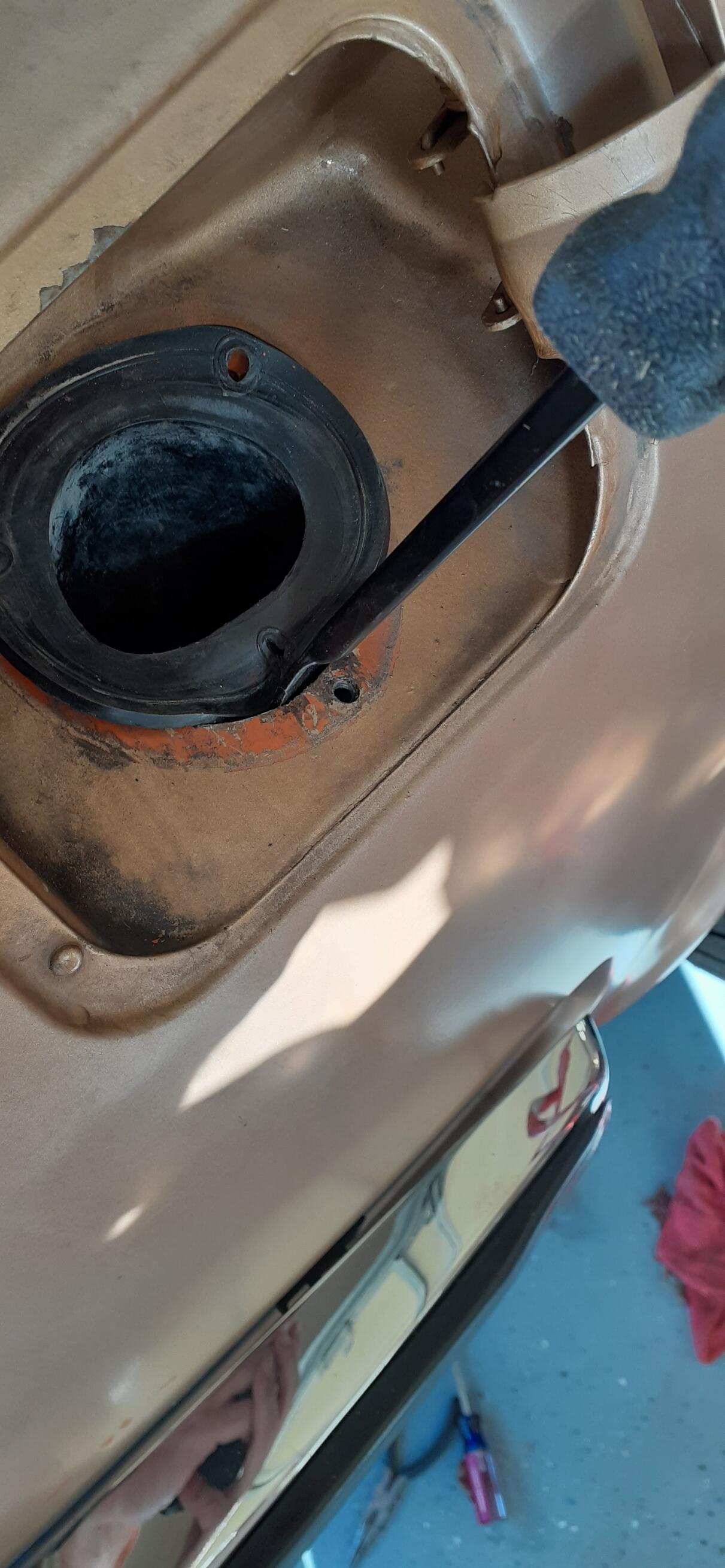
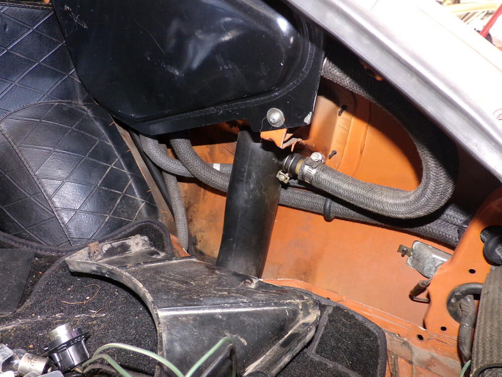
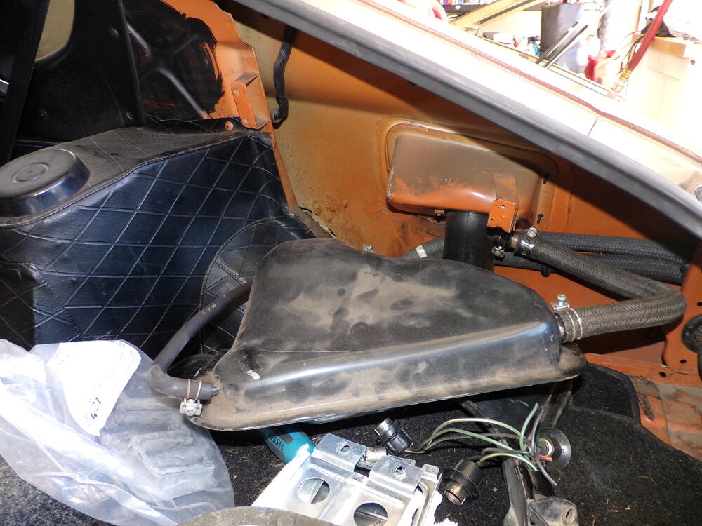
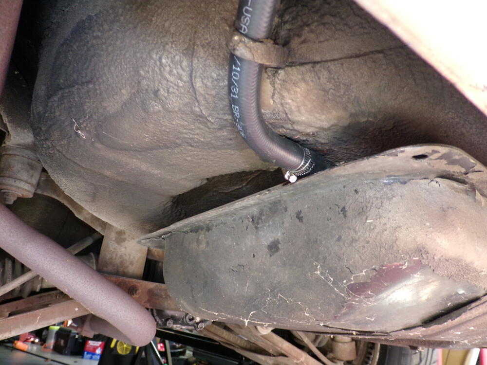
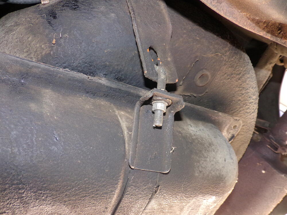
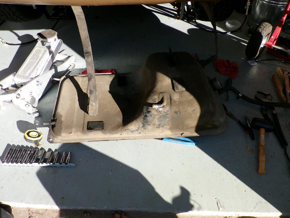
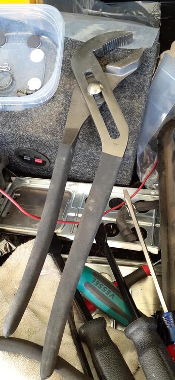
So I finally had some energy and motivation today. That meant I could drop the old tank. In case anybody needs a primer on dropping the tank, this may help. I already had the trim panels removed and the gas tank drained. Next is taking hoses off the expansion tank to give slack underneath. The only hoses that IMHO have to be removed is the large vent hose that goes through the floor on the right side near the tail panel to the tank and the hose from expansion tank to filler neck. Taking off the other hoses just ease access to the large vent hose. It's good to have some small picks to run along the inside of the hose where it is on the neck of the expansion tank to break loose the hose. I replaced all of the vent hoses only 24 years ago, so they are in fairly good shape. Go ahead and remove the 3 screws on the filler neck. There is only one vent hose that is somewhat accessible before starting to drop the tank. It's on the left side of the tank. Even then, you'll need to loosen the nuts on the J-bolts some to get full access to it. Before you take off the J-bolts, on the passenger side, remove the leads to the fuel sender and the supply and return hoses. With the driver side vent hose removed, and the tank straps disconnected from the J-bolts, you should be able to access the small vent hose on top of the tank. It is a good idea to support the left side of the tank with a floor jack or jack stands to keep from stressing the hoses. You'll also want to get the filler neck down to access the hose clamp holding the filler to the tank. That was a challenge for me this time. At first I tried to pry the lip in. That didn't work so great. Then I got out the big honkin' pliers and squeezed the neck enough to get the lip through the top hole. At that point, I fed the large vent hose through the floor to give enough slack for the tank to come down more. I got the large vent hose off the tank. Then I used a small pry bar to push the filler neck hose off of the tank. The tank was on the ground. I don't think it was as bad inside as the one @siteunseenhad with his display of chips that he likes to use, but I don't want to take any chances. The old tank is in the shed for now. I'll probably try to clean it up. The new tank will go in the week of Thanksgiving since I'm taking off from work that week.


-
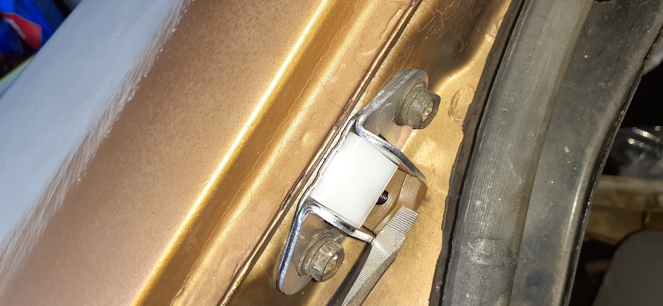
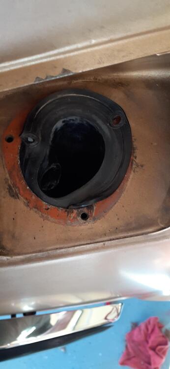
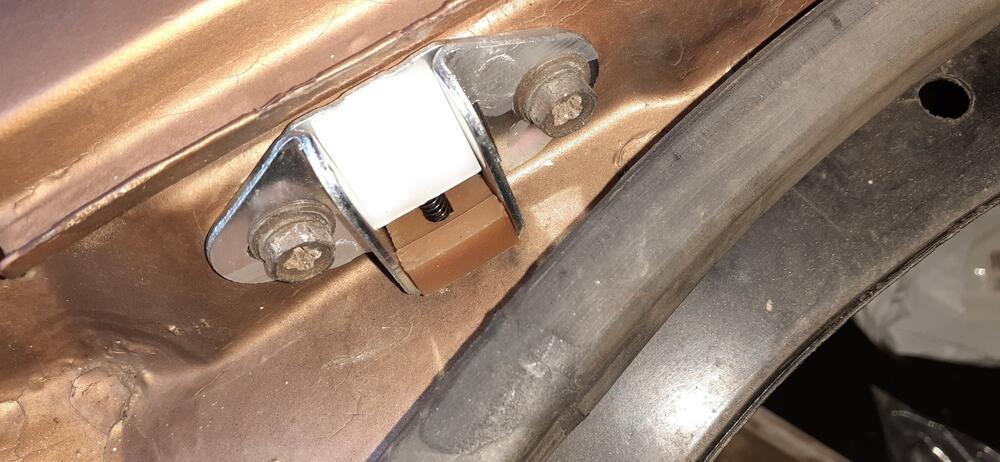
Here are a couple of pictures of a new stopper. The lower rubber piece is about 10 mm tall at the thickest point. I think that ridge is about 3 mm thick. As you can see it is quite pliable. I hope this helps in your thoughts to restore them. Frankly for me, it was too easy to spend a little money and never have to think about it again.

-
Yep. @One Way The lower block that disintegrated is made of rubber on the factory ones. I just put a set on my 240Z recently. It is a relatively soft rubber, too. Maybe I can shoot some photos and video after I'm done wrestling with the gas tank today.
-
Post photos of the front calipers showing the bleed screws.
-
-
-
-
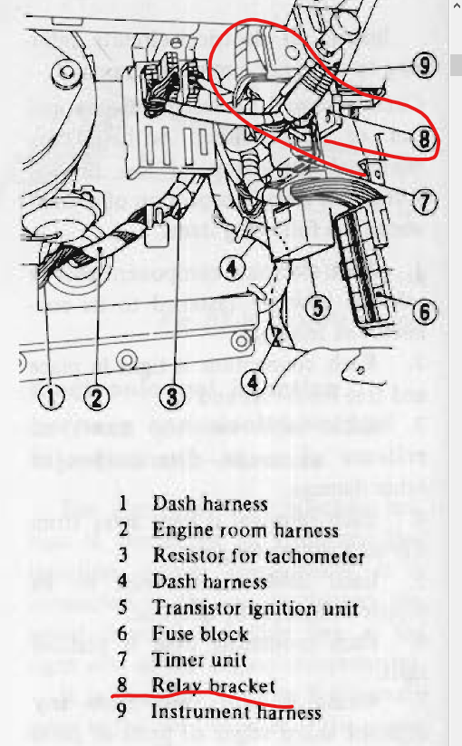
Oh, and I bought one of these 7 years ago, but it doesn't have a tachometer. https://www.amazon.com/gp/product/B000BSWEHS/ It still works, but I have to use a separate tachometer when tuning.
-
Timing lights are hit and miss anymore. The Innova Digital should do what you need for a timing light. https://www.amazon.com/dp/B000EVYGV4
-
It is possible your readings will go up since the other cylinders won't be pushing as hard against the cylinder under test.