Matthew Abate
Free Member
-
Joined
-
Last visited
Everything posted by Matthew Abate
-
 I think you’re right. I would rather have the split one (15415) so the pipes tuck up better, but I don’t want to order it and find out it doesn’t line up with the twin pipe indentations on the r180 crossmember.
 -
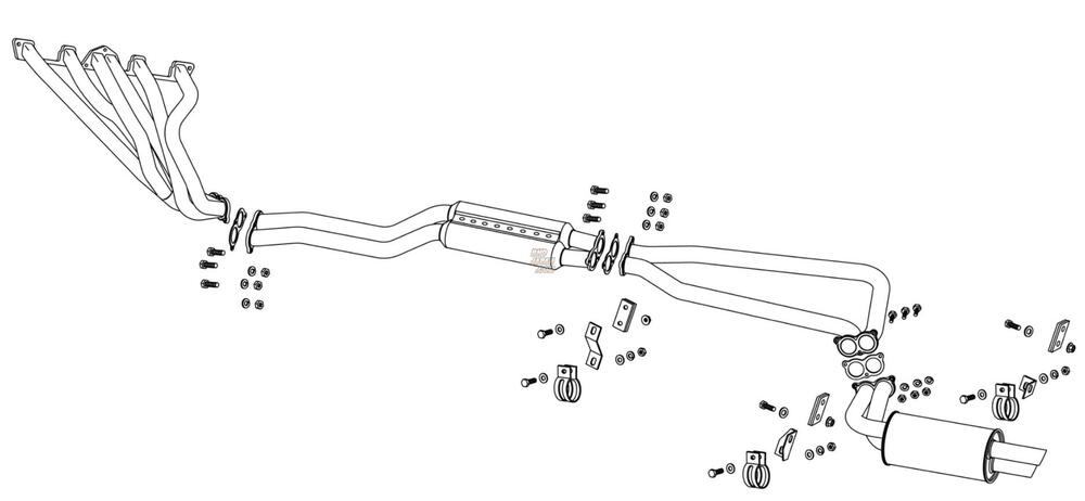
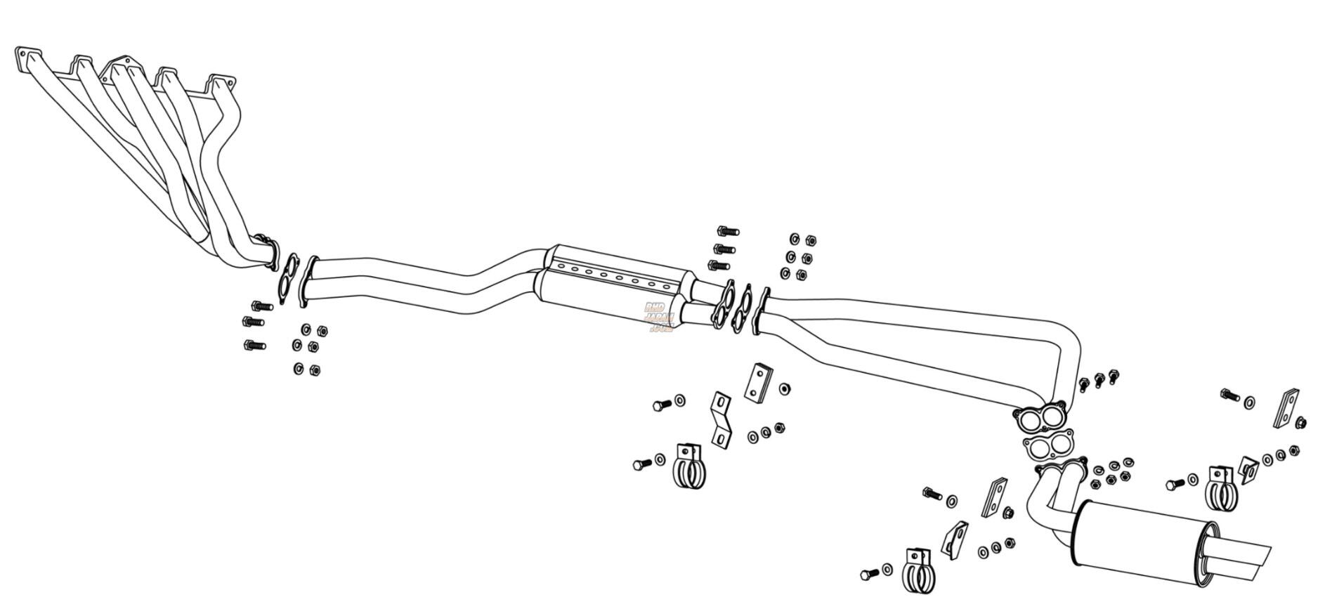
This is the information Fujitsubo has listed on their product description for the EPU system: Product Name - EXH PERFORMANCE UNIT (Legalis) Item Number - 050-15413 Price Price - ¥313,500 (Base price: ¥285,000) JAN Code - 4944997019149 Supported model application - S30 Fairlady Z 2 Seater Body Type - S30 (2 Seater only, Manual Transmission vehicles only) Engine type - L20 Year - 1969.11 - 1975.9 Special Notes: Compatible with low-down [lowered] vehicles It is a set of EX manifold + muffler (4 divisions). It is not compatible with genuine and other exhaust parts. Common to Solex, Weber Cab, and SU Cab Genuine SU cab car * Heat shielding required It cannot be installed in a car equipped with a genuine air cleaner box. Specifications: Outlet shape Tailip Style - φ50.8 slash (W, vertical) Pipe Diameter Pipe Diamet er - EX: φ45.0-50.8, Muffler: φ50.8 Dual List of Fitting Parts 080-35098 Plate Gasket Plate Gasket x 3 M8 x 35mm Bolt x 9 12 M8 spring washers M8 Nut x 12 M8 x 25mm Bolt x 3 M8 plate washer (small) x 9 S30 exclusive metal fittings (band type φ50.8) x 3 Dedicated bracket for S30 [A] x 1 Dedicated bracket for S30 [B] x 1 Dedicated bracket for S30 [C] x 1 Insulation mat (80 x 100) x 1 Stainless steel wire (l250) x 2 Product Name - EXH PERFORMANCE UNIT (Legalis) Item Number - 050-15415 Price Price - ¥313,500 (Base price: ¥285,000) JAN Code - 4944997019156 Supported model application - S30 Fairlady Z 2 Seater Body Type - S30 (2 Seater only, Manual Transmission vehicles only) Engine type - L20 Year - 1969.11 - 1975.9 Special Notes: Compatible with low-down [lowered] vehicles It is a set of EX manifold + muffler (4 divisions). It is not compatible with genuine and other exhaust parts. Common to Solex, Weber Cab, and SU Cab Genuine SU cab car * Heat shielding required It cannot be installed in a car equipped with a genuine air cleaner box. Specifications: Model Type - R200 Diff compatible model Outlet Shape Tailip Style - φ50.8 slash (W, vertical) Pipe Diameter Pipe Diameter EX: φ45.0-50.8, Muffler: φ50.8 Dual List of Fitting Parts 080-35098 Plate Gasket Plate Gasket x 3 M8 x 35mm Bolt x 9 12 M8 spring washers M8 Nut x 12 M8 x 25mm Bolt x 3 M8 plate washer (small) x 9 S30 exclusive metal fittings (band type φ50.8) x 3 Dedicated bracket for S30 [A] x 1 Dedicated bracket for S30 [B] x 1 Dedicated bracket for S30 [C] x 1 Insulation mat (80 x 100) x 1 Stainless steel wire (l250) x 2 --- This is what I found on JDM Car Parts: Part number: #15-510-15418 Fujitsubo EPU Stainless Steel Dual Exhaust System for Datsun 240Z / Nissan Fairlady Z S30 L6 Engine L6 L20-L28 Engine Headers: 6-2 Type / 45mm at 6 and 50.8mm at 2 Exhaust pipe: 45 mm to 50.8 mm 50.8 mm at Straight section This system is for triple carburetor set up Designed to work with lowered suspension set up. Works with RHD / LHD car Works with R200 Differential set up Comes with insert for O2 Sensor set up (O2 sensor is not included) Caution: It does not come with manifold gasket (Stock manifold gasket works with this headers) Caution: Exhaust hangers are Not included. You need to use stock hangers --- This is what I found on RHD: Fairlady Z S30 GS30 HS30 2-Seater Part Num: 050-15415 Series: Exh Performance Unit EPU Legalis Material: Stainless Steel (SUS304) Tip Type: Slash (W Vertical) Tip Diameter (mm): 50.8 X 2 Pipe Diameter (mm): 50.8 --- This is what I found on Blackhawk Japan: Series Name: EXH PERFORMANCE UNIT (LEGALIS) Product Number - 050-15415 Compatible Car - FAIRLADY Z 2-SEATER S30 Product Description Body model: -S30 Engine model: L20 Year: S44.11 to S50.9 (1969.11 to 1975.9) Tailtip Style: φ50.8 Slash (W, vertical) Pipe Diameter : EX: φ45.0-50.8, Muffler: φ50.8 Dual Fitting Parts: 080-35098 Plate Gasket × 3 M8 × 35mm Bolt × 9 M8 Spring Washer × 12 M8 nut x 12 M8 x 25mm bolt x 3 M8 plate washer (small) x 9 S30 dedicated metal fitting (band type φ50.8) x 3 S30 dedicated bracket [A] x 1 S30 dedicated bracket [B] x 1 S30 dedicated bracket [C] x 1 Insulation mat (80 x 100) x 1 Stainless steel Wire (l250) x 2 Peak Power: Standard (STD): -dB FUJITSUBO: 95dB Peak Torque: Standard (STD): -dB FUJITSUBO: 92dB Proximity Exhaust Noise: Standard (STD): -dB FUJITSUBO: 89dB Remarks Safety standard compliant product 2-seater only MT car only Low-down car compatible R200 differential compatible EX manifold + muffler (4 divisions) set product Not compatible with genuine and other exhaust parts Common to Solex, Weber cab, and SU cab vehicles Genuine SU cab vehicles Heat shield shield required Vehicles with genuine air cleaner box cannot be installed Notes: Images are for illustration purpose only. Actual product may vary. --- So it looks like 15413 is for an r180 differential and 15415 is for an r200 differential, but the information is so inconsistent from one retailer to another that I am not sure about any of it. I don't know if 15418 is a typo or what. I see exhaust hangers in the illustration and think that's what the brackets in the parts inventories are, but who knows. Another thing I am finding is HUGE swings in price, from $1,404.46 to $3,299.00, and that is just within the EPU versions. I reached out to JDM Car Parts but he hasn't responded yet. I have also reached out to Fujitsubo and Greenline Motorsports. Maybe one of them will respond.
-
Yes! Super helpful. I found a set of copper lines and a dryer on eBay and was thinking of using them for a vintage air setup, but couldn’t see how they went on. Not sure if I’m going that route or not because I’m concerned about leaks, but at least now I know where the lines go.
-
It’s a full system, so part numbers include the header. I found three: 15413 15415 15418
-
RTV seems to do the trick. unrelated… Does anyone know of a build thread with really good pictures of the original copper 280z air conditioning lines and hoses? I want to see how those were routed and where they went through the firewall so I can approximate that with my setup. I haven’t been able to find a diagram that show the actual routing.
-
Doesn’t look like Streeter Corp can help with the details, although I will probably still order through them. Here’s what they said about my questions: As we operate wholesale with the manufacturers we can't really be digging into deep info about particulars, that's not the kind of retail service we provide to you or them to us. These were my questions: 1. I can tell the EPU is a full system, but I can’t tell if the header is the same as the Super Ex or if it has also been updated. 2. I see that the EPU version can accommodate an r200 differential, but does it still work with a r180 and the factory cross member that has indents for a twin pipe exhaust? 3. I saw one website saying the EPU version has an O2 sensor, but I wasn’t sure where it is. Is it on the header or the y-pipe? 4a. Is the EPU system a bolt in setup in a left hand drive car, or is there going to be a clearance issue with the steering shaft hitting the header? 4b. Related to this, are all of the hanger brackets welded on already? 5. Are there any other changes to the EPU over the Legalis r / super ex that explain the price increase over the older setup?
-
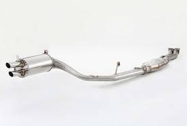
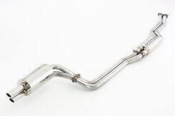
I know this thread is old… and, um, tense… but it’s also the best resource for info on the Fujitsubo 240z systems on the internet… if you dig through it. So I’m posting an update in case people weren’t aware: Fujitsubo have a new new version of the Legalis R on the market. It is the EXH Performance EPU version (15-15415) and from what I can tell it’s updates are an O2 sensor and rerouting the pipes at the rear of the car to split before and wrap around the dif. So that make three versions you can buy online right now: The original with the fatter resonator: The updated one with tucked up adjacent pipes: And this one with the split: It also looks like it only comes as a total system packaged with the Super Ex header. There are many things I’m not clear on, though. The split in the pipes accommodates an r200, but does that mean it doesn’t align with the depressions for the twin pipes on a stock r180 differential mount? We’re there changes made to the Super Ex that helped achieve their supposed performance gains (this is supposed to improve performance over the 2nd version)? Does everything fit nicely on a LHD car, as compared to either of the previous versions)? I reached out to Fujitsubo via Instagram for details but doubt I will hear anything. The retailers can’t answer these questions either.
-
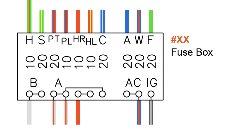
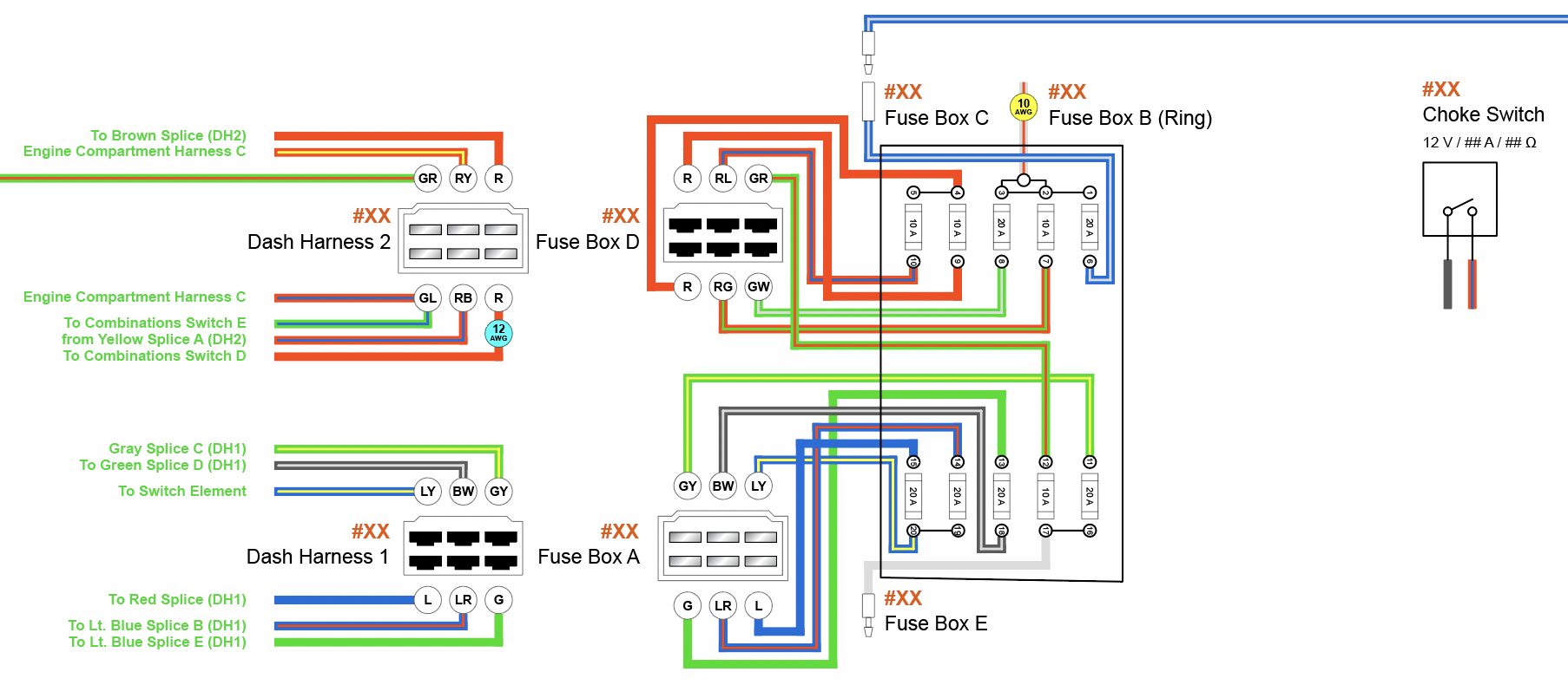
I've started to redraw my wiring diagram. To give you an idea of how I am changing it from what we have on the site now, here's the fuse box from the original followed by the one I redrew. I wish I could say this will be useful for everyone, but I will be deleting and adding a bunch of components, so it's utility for other people will be limited. Diagram: Sample:

-
I plan to use LEDs but I want to wire the car so that I don’t HAVE to use LEDs, particularly for the headlights. My thoughts on having 14 AWG be my smallest wire was coming from a few things: First, the amount of fried wiring I found. It’s possible the heat came from outside but in places like under the dash I don’t know what would cause that, so I was assuming that it was overload on the wiring. Second, the general use of 10-amp fuses for everything that wasn’t one of the fatter wires, plus the gauge charts I’ve been using. However, I suspect the dash maybe could come down a notch for all the instruments and save me some headaches with fitting all that stuff in there. Third, just eyeballing stuff looks like a lot of 14 AWG. Maybe I’m off base and It's smaller than that. Tough to tell since it's actually Japanese (square millimeter?) wire and not AWG. need to go back over it more carefully. I would love to plug all the numbers for everything in the car into a calculator, but I just don’t know where to find that information.
-
I did a quick tally of which wires need to be which gauge and this is what I ended up with: Components Gauge Wire Color Starter Ground, Combination Switch 10 Black Black w/ White Fuel Pump Green Headlights Red w/ White Starter, Ammeter White Alternator, Ammeter White w/ Red 12 Black w/ White Ignition Switch Black w/ Yellow Ignition Switch Green w/ White Headlights, Combination Switch Red Rear Glass Defroster Red w/ Black Light & Horn Switch Red w/ White Headlights Red w/ Yellow Fuse Box White Ignition Switch, Combination Switch White w/ Red All others would be 14 AWG. There may be some 16 or 18 AWG in the car originally, but I don't see a reason to go that light. Please let me know if you think I have any errors here. I'm also wondering if it would be worthwhile to step everything up one level, or if that would be a waste of money and weight.
-
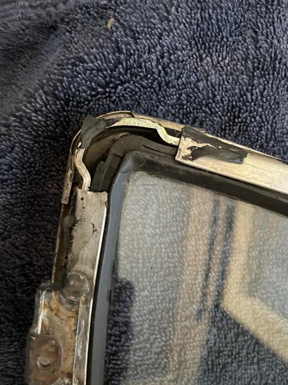
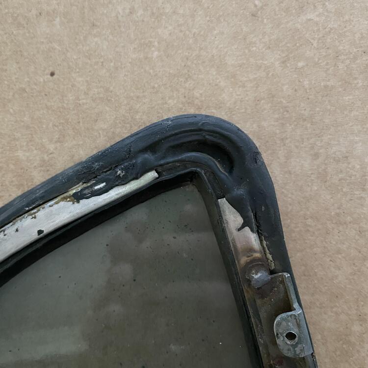
Question about the black goop inside the frames for my rear quarter panels: what is it? I was thinking RTV or body caulk. It doesn’t seem like it’s weatherstrip adhesive. I want to be able to replicate this after I clean all my parts up.
-
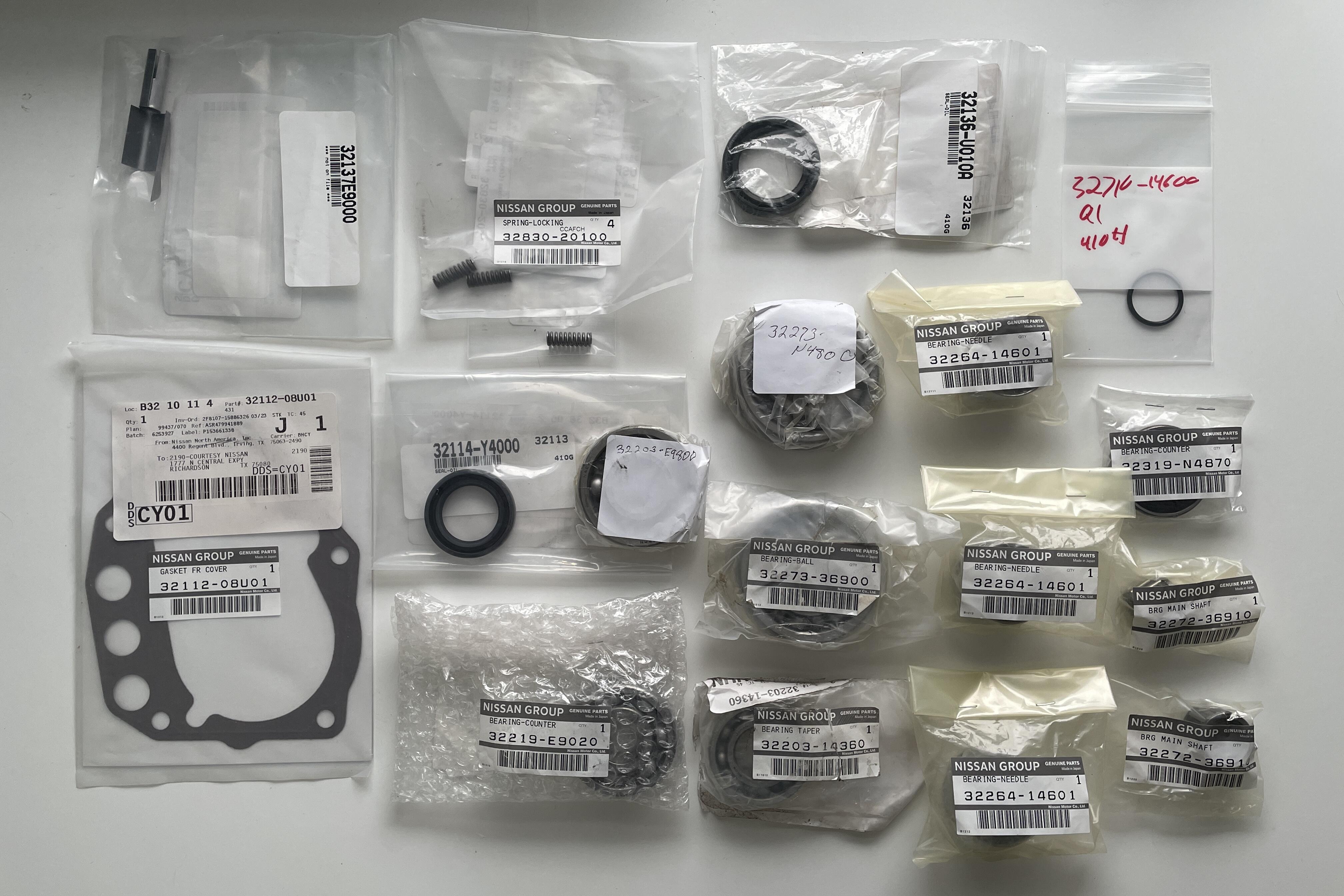
I received the last of the parts I ordered for the 5-speed overhaul on Sunday this past weekend, so three weeks total wait time. Not bad considering one of the bearings was lost in transit to Courtesy Parts and had to be ordered again. Not as fast as ordering a quest kit, but I went above and beyond what's available in those, plus it's all OEM.
-
Side Project: I was able to find Nissan OEM versions of everything I need to overhaul the five speed. Luckily, I don’t need synchros, although you can still get them OEM from Courtesy Parts and the handful of Nissan dealers I called. I had to use a handful of places to get all of these, and I’m not 100% certain two of these are OEM despite reassurances from the retailer, but it wasn’t difficult to get it all in hand. Maybe 30 minutes on Google. I dropped these off at the transmission shop yesterday. I have no idea how long it is going to take for him to get it done, but I’m hoping to have it back by the end of September. Here's my parts list: - 1x Main Input Shaft Bearing (PN 32273-N4800) - 1x Main Input Shaft Bearing, Adapter Plate (PN 32273-36900) - 1x Main Input Shaft Bearing, Extension Housing (PN 32203-14360) - 1x Pilot Bearing, Input / Output Shafts (PN 32272-36910) - 3x Needle Bearing, Main Shaft Gears (PN 32264-14601) - 1x Counter Shaft Bearing, Front (PN 32219-E9020) - 1x Counter Shaft Bearing, Adapter (PN 32203-E9800) - 1x Counter Shaft Bearing, Rear (PN 32319-N4870) - 1x Reverse Idler Gear Bearing (PN 32272-36910) - 1x Front Cover Gasket (PN 32112-08U01) - 1x Oil Gutter (PN 32137-E9000) - 1x Front Seal (PN 32114-Y4000) - 1x Rear Extension Seal (PN 32136-U010A) - 3x Checking Spring (32830-20100)

-
My kids dinged the front left fender the other day with the door from our Subaru, so I am trying to embrace the concept of Wabi-sabi. The goal here is a Z built from the “best” parts that will go on it, or, a Z that’s what Nissan could have made if they went all out in the beginning. Trying to keep the newer tech / styles to a minimum. But yeah, I’m getting itchy.
-
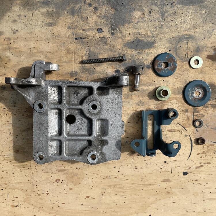
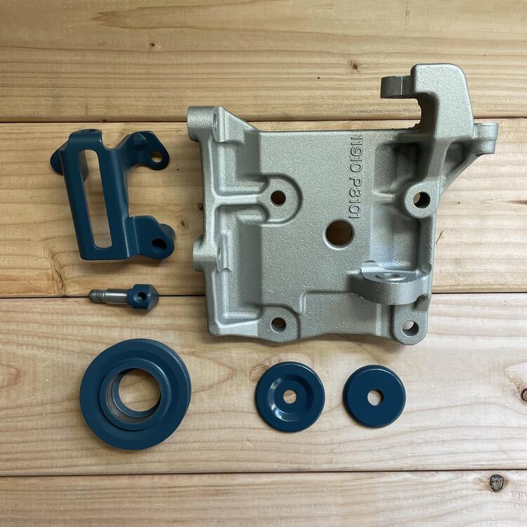
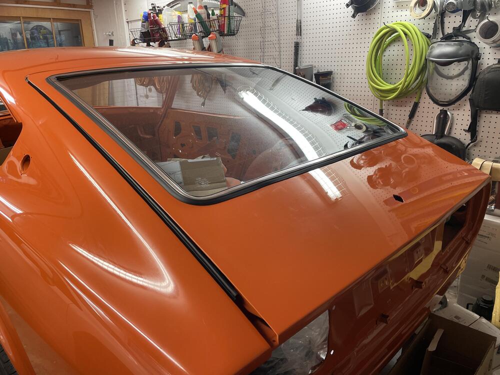
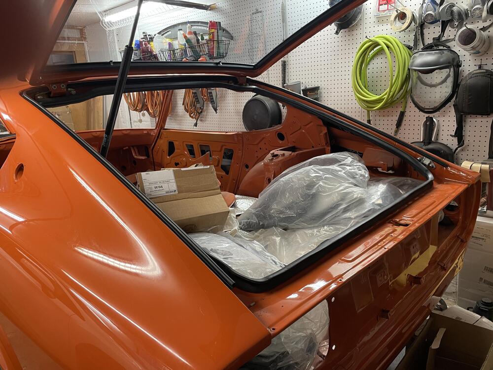
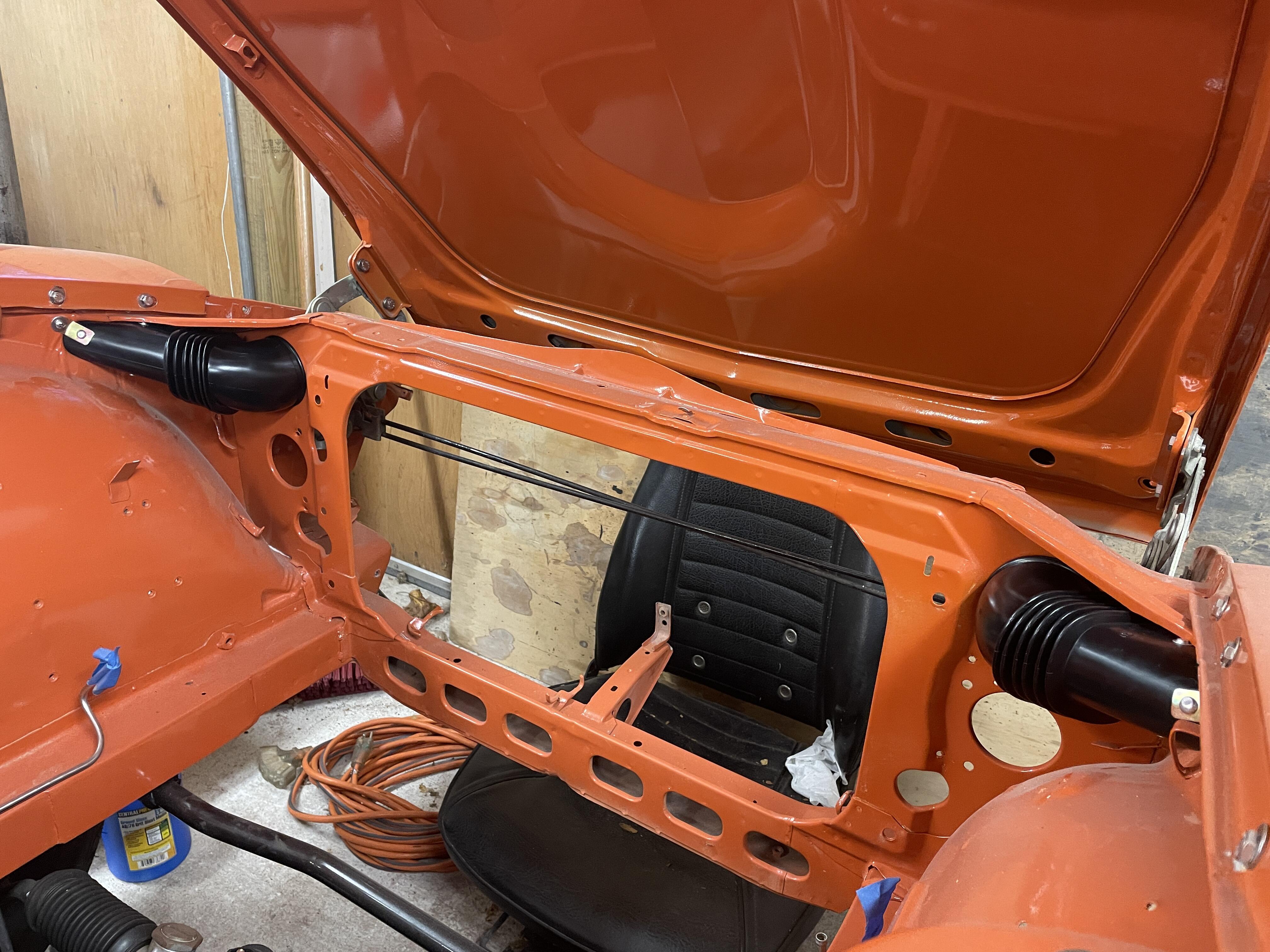
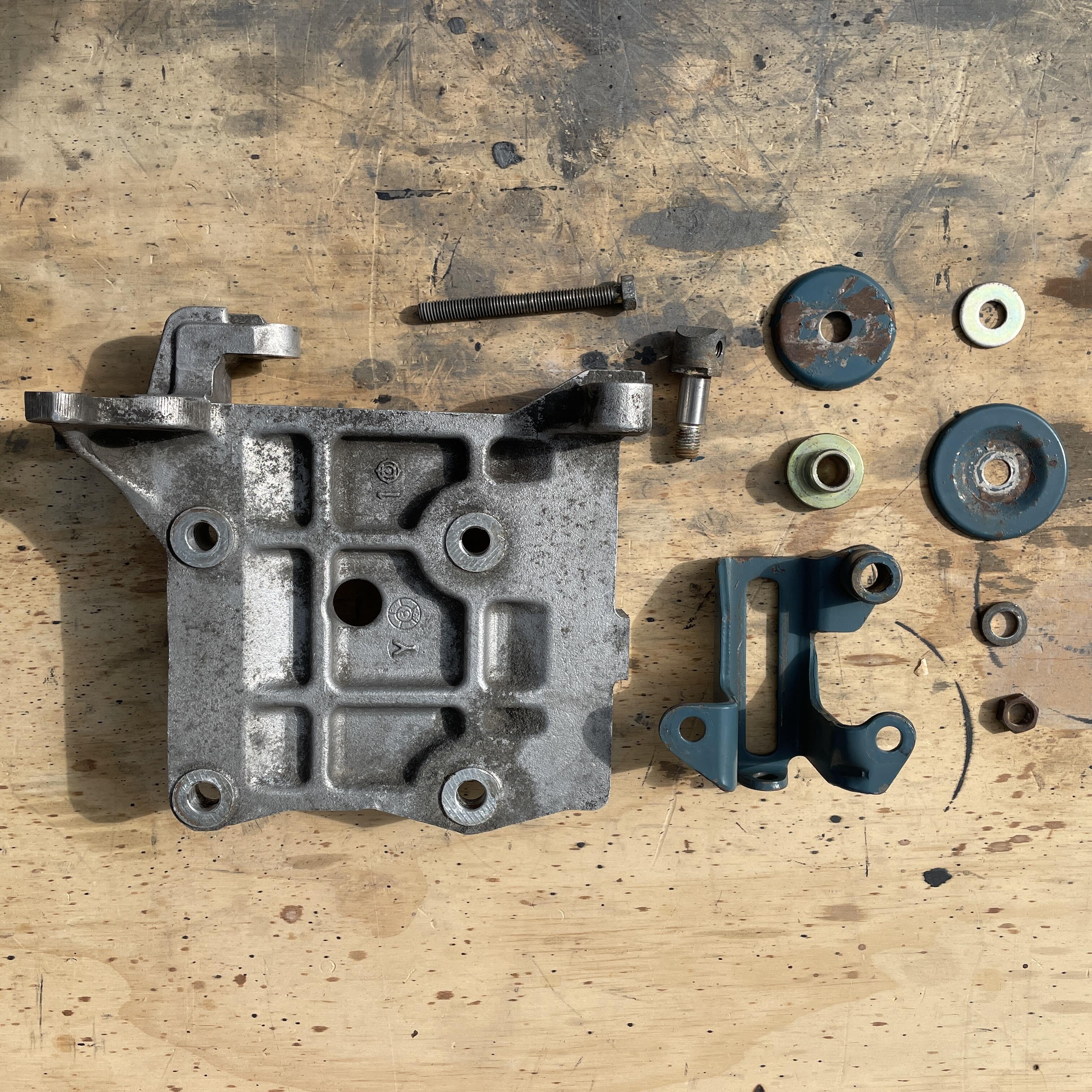
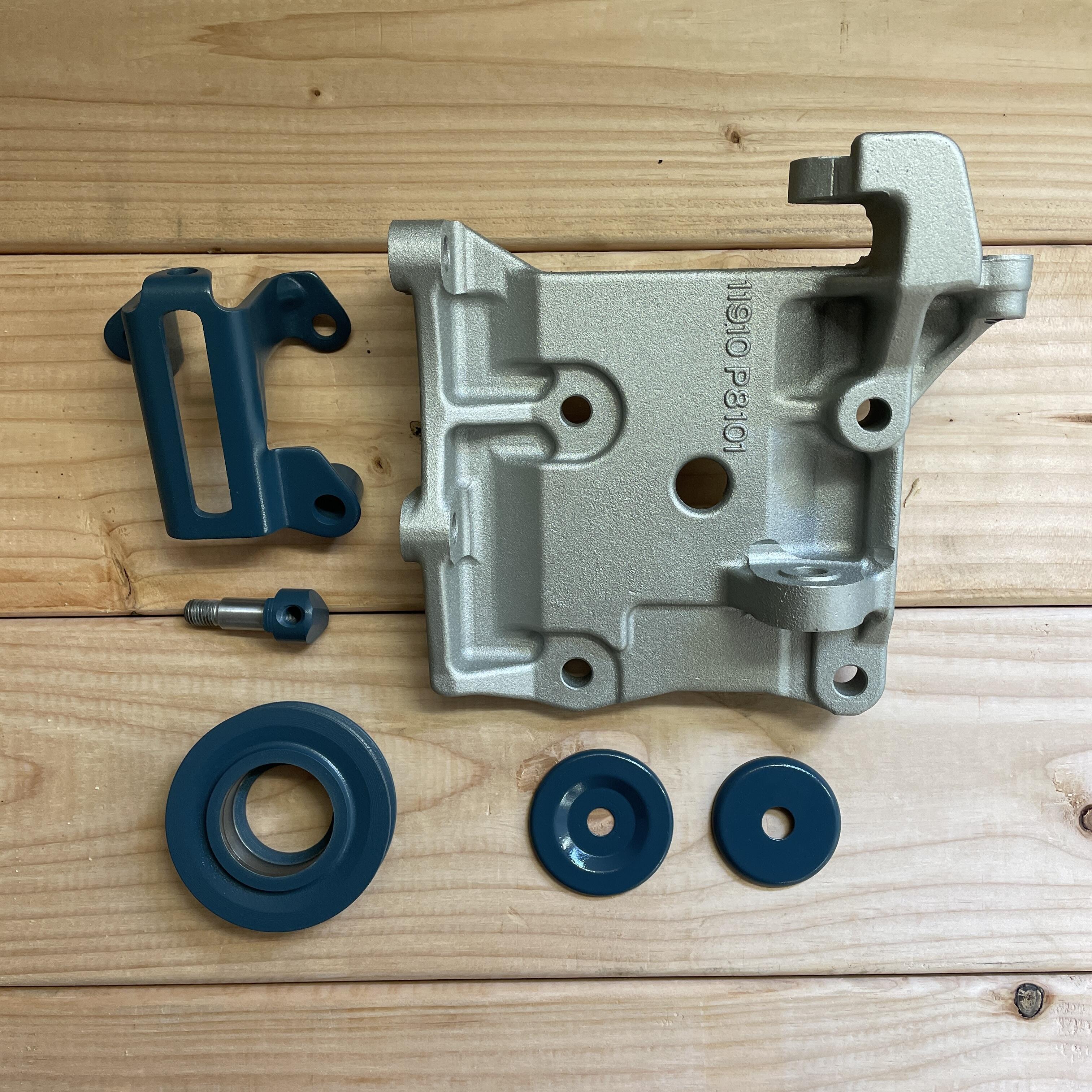
Some updates: Fresh air intakes ZX AC Bracket ZX AC Bracket after sandblasting and paint That same ‘78 280z rear glass with an OEM rear window seal to fix this gaps in the corners. This was a major PITA to install. Super tight. I also noticed a scuff in the shape of a Z logo. I think there was a sticker or paint on the glass and they didn’t take care getting it off. Gonna have to polish guy. Inner and outer (1970 version) weather strips

-
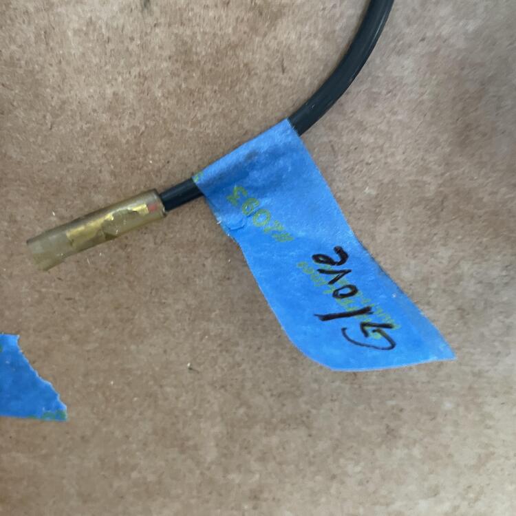
Table Number 4! This table represents the other half of the dashboard harness for a 1973 240z (PN 24013-M3322). It was much easier than the other half. There only two items I couldn't figure out: a missing wire in the blue 10-pin connector to the engine harnes and a blue wire near the fuse box branch what might be power to the Radio (pink cells). Pretty close to done with this inventory now. I have some small harnesses to capture still (fuel pump harnesses and the heater controls harness), but I don't think I need them for my final build so I may do that later. 1973 240z Dashboard Harness (24013-M3322) Inventory Position Component Connector Color Connector Style Connector Image Direction # of Pins # of Wires Diagram Wire Color Sample Wire Color Min. Feet of Wire Needed 1 Engine Harness A Blue Nylon 10-Prong Male 10 9 Blue w/ White Blue w/ White 1 (to Lt. Blue Splice D) Red Red [See Fog Light Switch] Black w/ Yellow – Red w/ Black Red w/ Black [See Body Harness Aux] Yellow w/ Green Yellow w/ Green 1 (to Lt. Blue Splice A) Red w/ Black Red w/ Black [See Light & Horn Switch] Red w/ White Red w/ White (Thick) 5 (to Gray Splice) Green w/ Black Green w/ Black [See Light & Horn Switch] Green w/ Red Green w/ Red [See Fuse Box D] – – – 2 Engine Harness C White Black Nylon 10-Prong Male 10 8 Red w/ Blue Red w/ Blue [See Combinations Switch E] Red Red (Thick) 3 (to Brown Splice) Green w/ Blue Green w/ Blue 1 (to White Splice A) Red w/ Blue Red w/ Blue [See Fuse Box D] Red w/ Yellow Red w/ Yellow (Thick) [See Fuse Box D] Blue w/ Yellow Blue w/ Yellow [See Combinations Switch E] Yellow w/ Black Yellow w/ Black [See Combinations Switch E] Black Black 2 (to Lt. Blue Splice C) – – – – – – 3 Engine Harness F White Nylon Female 1 1 White White (Heavy) 2 (to Yellow Splice A) 4 Intermittent Relay White Nylon Female 6 4 Blue w/ White Blue w/ White 2 (to Lt. Blue Splice C) Blue Blue [See Combinations Switch E] Blue w/ Red Blue w/ Red [See Intermittent Relay Junction 2] Blue w/ White Blue w/ White 2 (to Lt. Blue Splice B) – – – – – – 5 Intermittent Relay Junction 2 Clear Bullet Male 1 1 Blue w/ Red 1 6 Body Harness Aux White Nylon Female 6 6 Red w/ Black Red w/ Black 1 Red w/ Blue Red w/ Blue 3 (to Yellow Splice B) Yellow w/ Green Yellow w/ Green 1 (to Lt. Blue Splice A) Black Black 6 (to Yellow Splice F) Red w/ Black Red w/ Black [See Junction 2A] Green w/ White Green w/ White 2 (to White Splice A) 7 Junction 2A Clear Bullet Male 1 1 Red w/ Black 1 Light Blue Splice A N/A N/A N/A N/A 2 Yellow w/ Green N/A Yellow w/ Green White Splice A N/A N/A N/A N/A 2 Green w/ Blue N/A Green w/ White 3 (to White Splice C) Light Blue Splice B N/A N/A N/A N/A 2 Blue w/ White N/A Blue w/ White Light Blue Splice C N/A N/A N/A N/A 2 Black N/A Blue w/ White Brown Splice N/A N/A N/A N/A 2 Red (Thick) N/A Red Yellow Splice A N/A N/A N/A N/A 2 White (Heavy) N/A White Yellow Splice B N/A N/A N/A N/A 3 Red w/ Blue N/A Red w/ Blue Red w/ Blue White Splice B N/A N/A N/A N/A 2 Red w/ Blue N/A Green w/ White 8 Radio White Nylon Female 3 2 Red w/ Blue Red w/ Blue 1 (from White Splice B) Black Black [See Junction 2B] 9 Junction 2B Clear Bullet Male 1 1 Black 1 10 Radio Illumination / Power - ? Clear Bullet Female 1 1 Blue Blue 3 (to Yellow Splice D) 11 Fog Light Switch White Nylon "T" Male 2 2 Red Red 4 Red w/ Green Green w/ White 2 (from White Splice B) 12 Fuse Box D White Nylon Male 6 7 Red Red (Thick) 2 (from Brown Splice) Red w/ Yellow Red w/ Yellow (Thick) 4 Green w/ Red Green w/ Red 4 Green w/ Blue Green w/ Blue [See Combinations Switch E] Red w/ Blue 4 Red w/ Blue Red w/ Blue 2 (from Yellow Splice A) Red Red (Thick) [See Combinations Switch D] 13 Fuse Box E Clear Bullet Female 1 1 White White (Thick) 3 (from Yellow Splice A) 14 Glove Box Light Clear Bullet Female 1 1 Red w/ Blue Red w/ Blue 1 (from Yellow Splice B) 15 Clock Power Clear Bullet Female 1 1 Blue Blue 1 (to Yellow Splice C) 16 Clock Illumination Black Bulb N/A 1 1 Red w/ Blue Red w/ Blue 2 (to Yellow Splice D) 17 Map Light Clear Bullet Female 1 1 Red w/ Blue Red w/ Blue 1 (to Yellow Splice C) White Splice C N/A N/A N/A N/A 3 Green w/ White 2 (from White Splice B) Green w/ White 3 (to White Splice D) 18 Ammeter Black Ring w/ Cap (Nylon in FSM) N/A 1 1 White White (Heavy) 2 (from Yellow Splice A) 19 Ammeter & Fuel Gauge Illumination Black Bulb N/A 1 1 Red w/ Blue Red w/ Blue 2 (to Yellow Splice D) Yellow Splice C N/A N/A N/A N/A 3 Blue N/A Red w/ Blue Red w/ Blue 20 Water Temperature & Oil Temperature Gauge Illumination Black Bulb N/A 1 1 Red w/ Blue Red w/ Blue 1 (from Yellow Splice D) Yellow Splice D N/A N/A N/A N/A 3 Blue N/A Red w/ Blue Red w/ Blue Red w/ Blue 21 Tachometer Illumination A Black Bulb N/A 1 1 Red w/ Blue Red w/ Blue 2 (to Yellow Splice E) 22 Tachometer Illumination B Black Bulb N/A 1 1 Red w/ Blue Red w/ Blue 2 (to Yellow Splice E) 23 Illumination Dimmer (Rheostat) Black Spade Male 1 2 Red w/ Blue Red w/ Blue 2 (from Yellow Splice D) Red w/ Blue 2 (to Yellow Splice E) Clear Spade Female 1 1 Red w/ Blue Red w/ Blue 1 (to White Splice D) 24 Cigar & Hazard Fiber Optic Light Source White Nylon Female 2 1 Red w/ Blue 1 (to White Splice D) – – Male 1 1 Black 1 (to Cigar Lighter) Gray Splice N/A N/A N/A N/A 3 N/A White Splice D N/A N/A N/A N/A 3 Red w/ Blue N/A Red w/ Blue Green w/ White 25 Steering Lock Switch Clear Spade Male 1 1 Black Black 3 (from Yellow Splice F) Clear Spade Female 1 1 Red Red [See Step Light Harness] 26 Light & Horn Switch White Nylon Female 3 3 Red w/ White Red w/ White (Thick) 2 (from Gray Splice) Red w/ Black Red w/ Black 6 Green w/ Black Green w/ Black 6 27 Combinations Switch D Clear Bullet Male 1 1 Red Red (Thick) 6 28 Combinations Switch E White Nylon Female 9 9 Blue w/ Yellow Blue w/ Yellow 6 Blue Blue 7 Blue w/ Red Blue w/ Red [See Junction 2C] Yellow w/ Black Yellow w/ Black 6 Red w/ Blue Red w/ Blue 6 Blue w/ White Blue w/ White 6 (from Lt. Blue Splice C) Blue w/ White Blue w/ White 6 (from Lt. Blue Splice B) Green w/ Blue Green w/ Blue 6 Green w/ White Green w/ White 2 29 Junction 2C Clear Bullet Male 1 1 Blue w/ Red 1 Yellow Splice E N/A N/A N/A N/A 3 Red w/ Blue N/A Red w/ Blue Red w/ Blue Yellow Splice F N/A N/A N/A N/A 2 Red w/ Blue N/A Red Yellow Splice G N/A N/A N/A N/A 2 Black N/A Black 30 Speedometer Illumination Top Black Bulb N/A 1 1 Red w/ Blue Red w/ Blue 1 (from Yellow Splice F) 31 High Beam Indicator Light Black Bulb N/A 1 2 Red Red 4 (to Brown Splice) Red w/ White Red w/ White 2 (from Gray Splice) 32 Speedometer Illumination Bottom Black Bulb N/A 1 1 Red w/ Blue Red w/ Blue 2 (from Yellow Splice E) 33 Hand Brake Junction Clear Bullet Male 1 1 Yellow w/ Green 6 (from Lt. Blue Splice A) 34 Step Light Harness Clear Bullet Male 1 1 Black Black 1 (from Yellow Splice G) Clear Bullet Female 1 1 Red w/ Blue Red w/ Blue 1 (from Yellow Splice F) 35 Door Switch LH Clear Bullet Female 1 1 Black Black 1 (from Yellow Splice G) Clear Spade Female 1 1 Black Black 3


.thumb.JPG.ca535c58a8d96842e7e1c6737b46eef6.JPG)
.thumb.JPG.e9077869fc479891258baf609f8bd8c5.JPG)


-
Amazing! So not only does that solve #7 in harness #1, it solves for position #5 in harness #2, which you would not know because I have not posted the table for yet. The only mysteries I will have left are the 4 wires that are missing (2 from the dash and 2 from the engine) and a blue connector on this harness I am chasing now, which might be to the radio lights. Maybe I can find those using the diagrams.
-
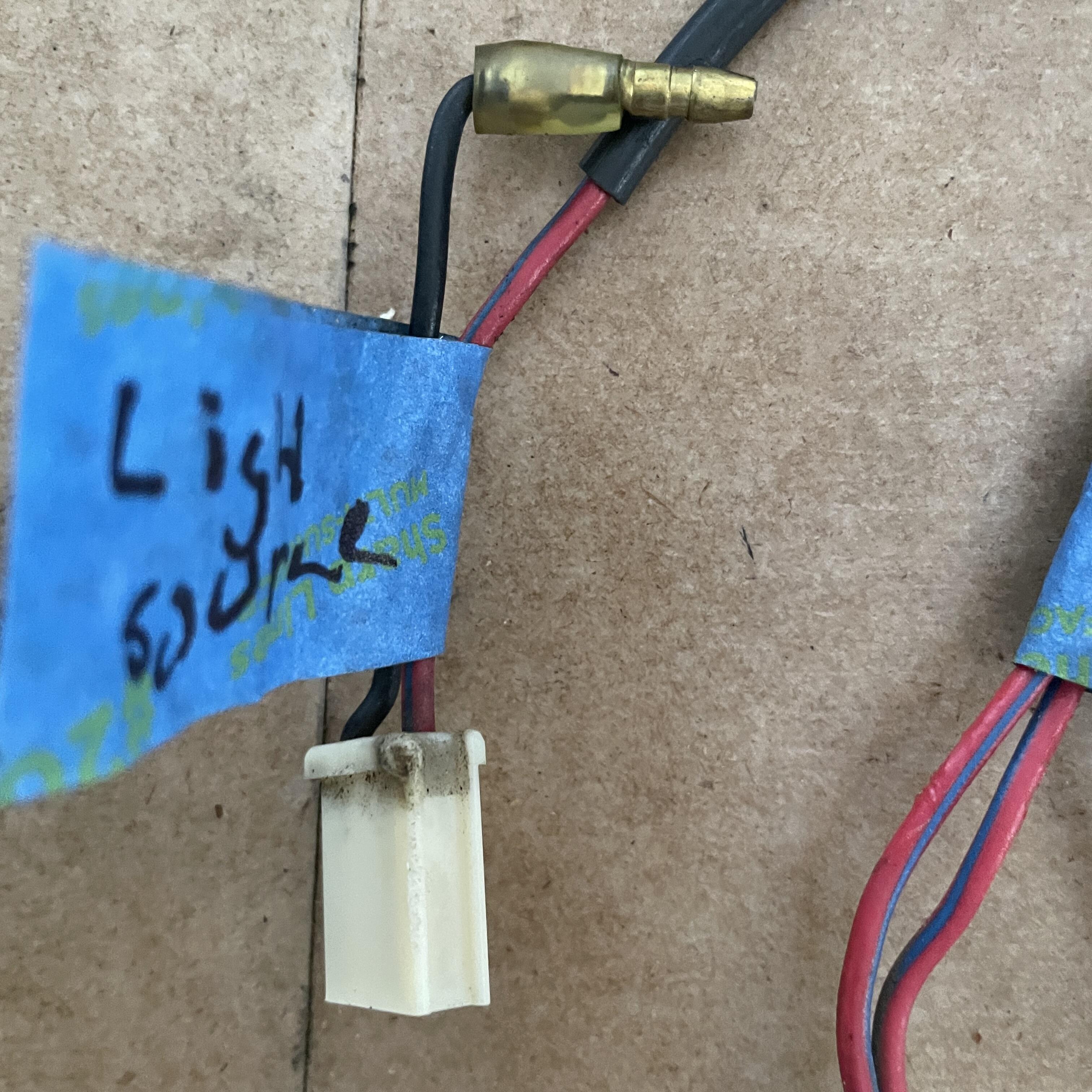
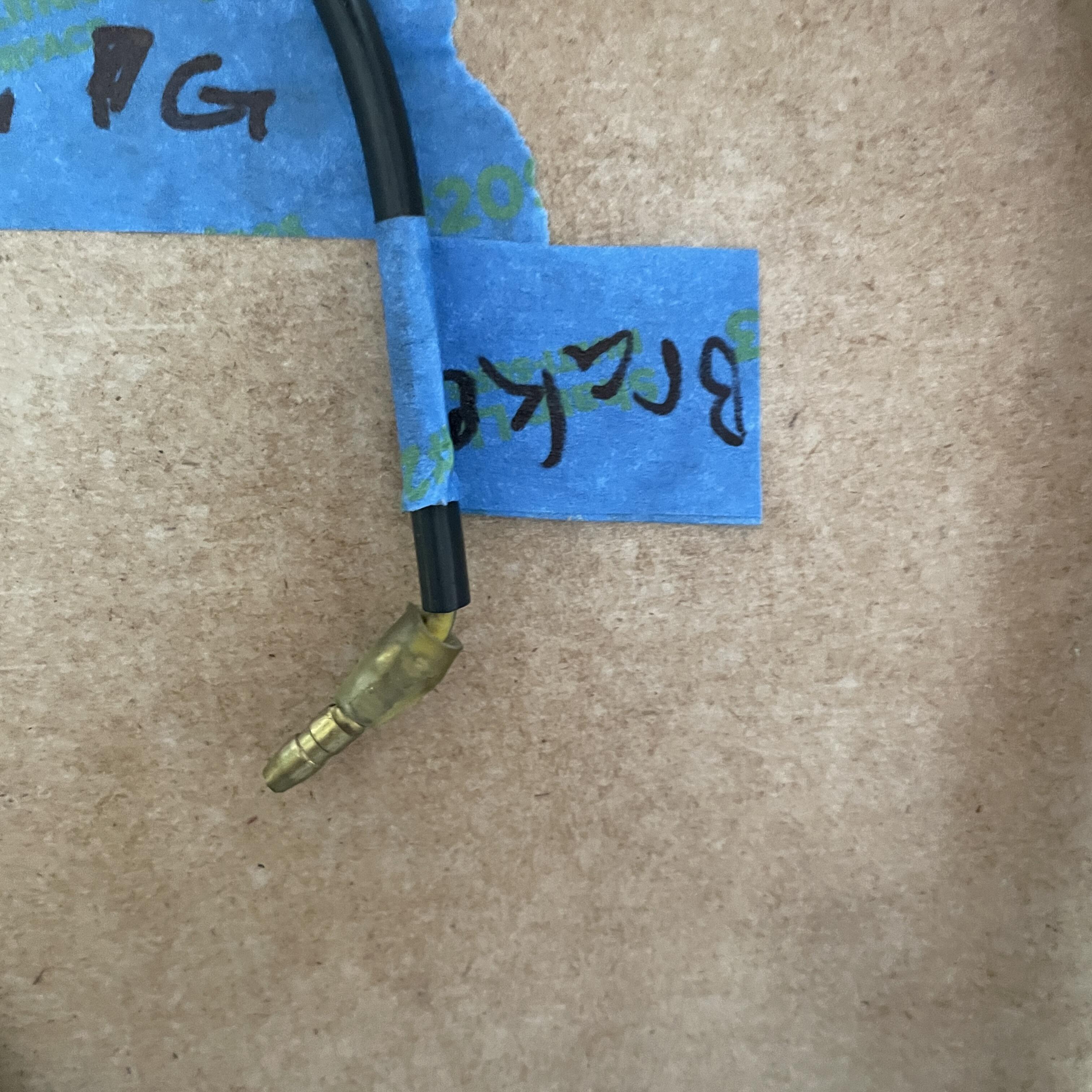
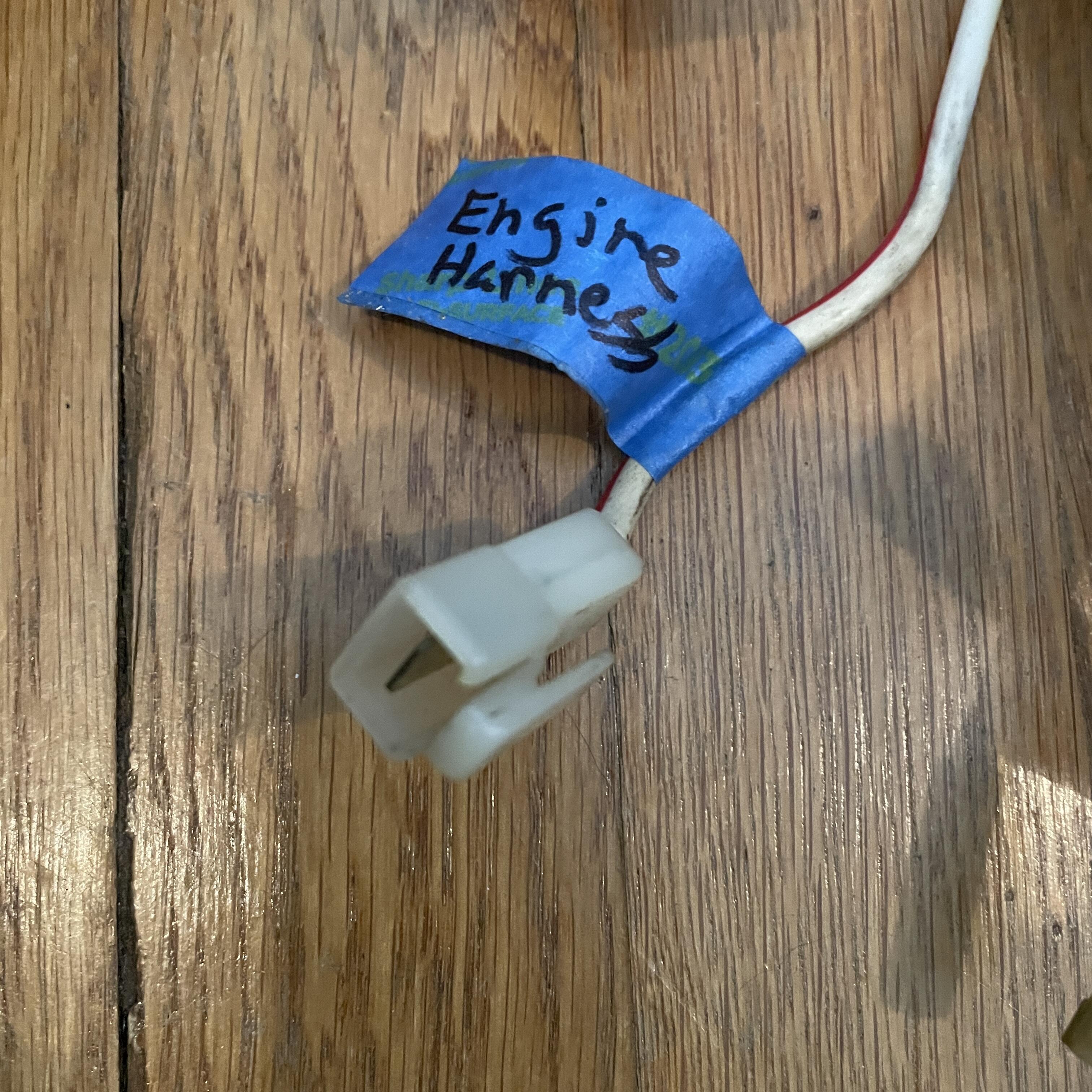
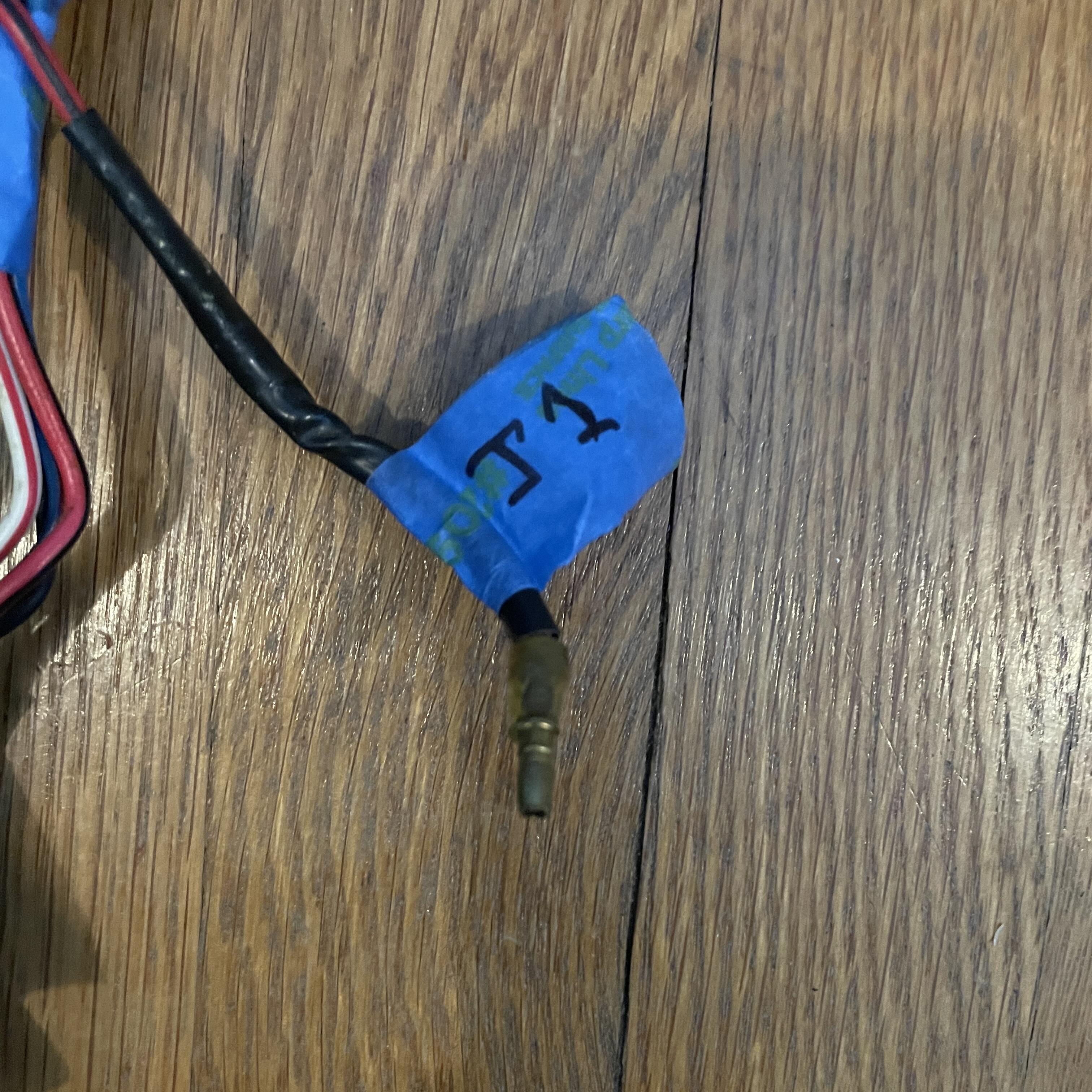
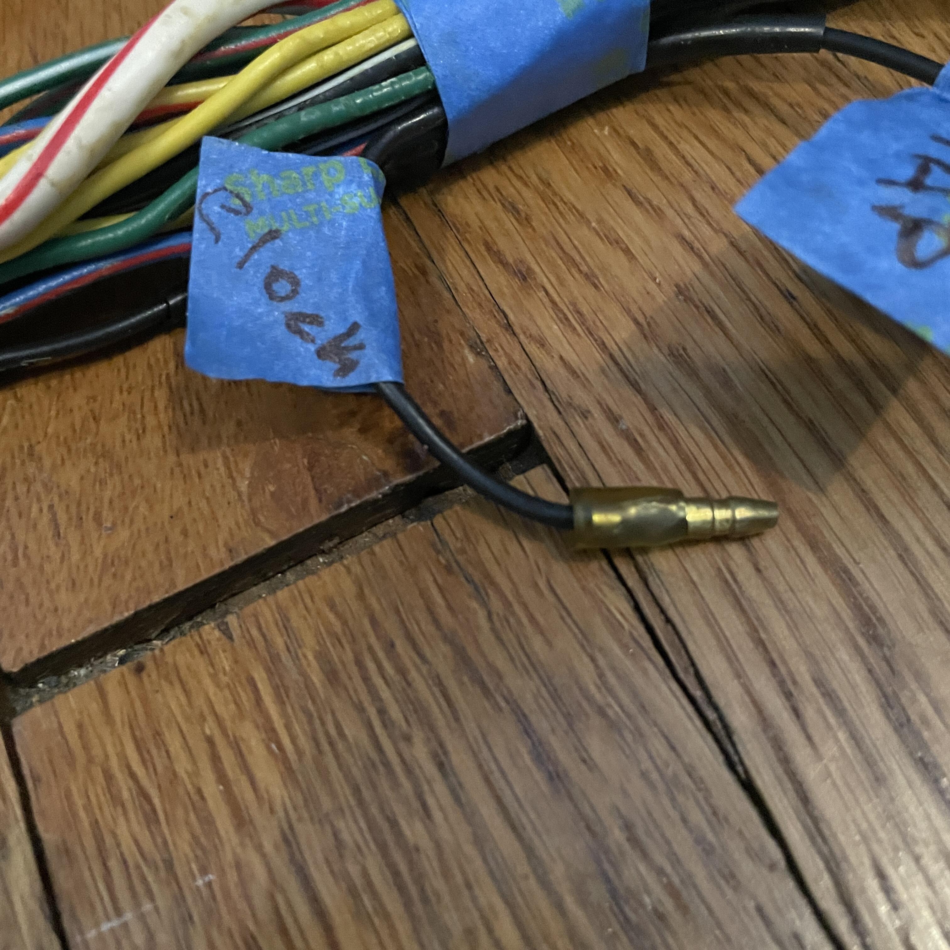
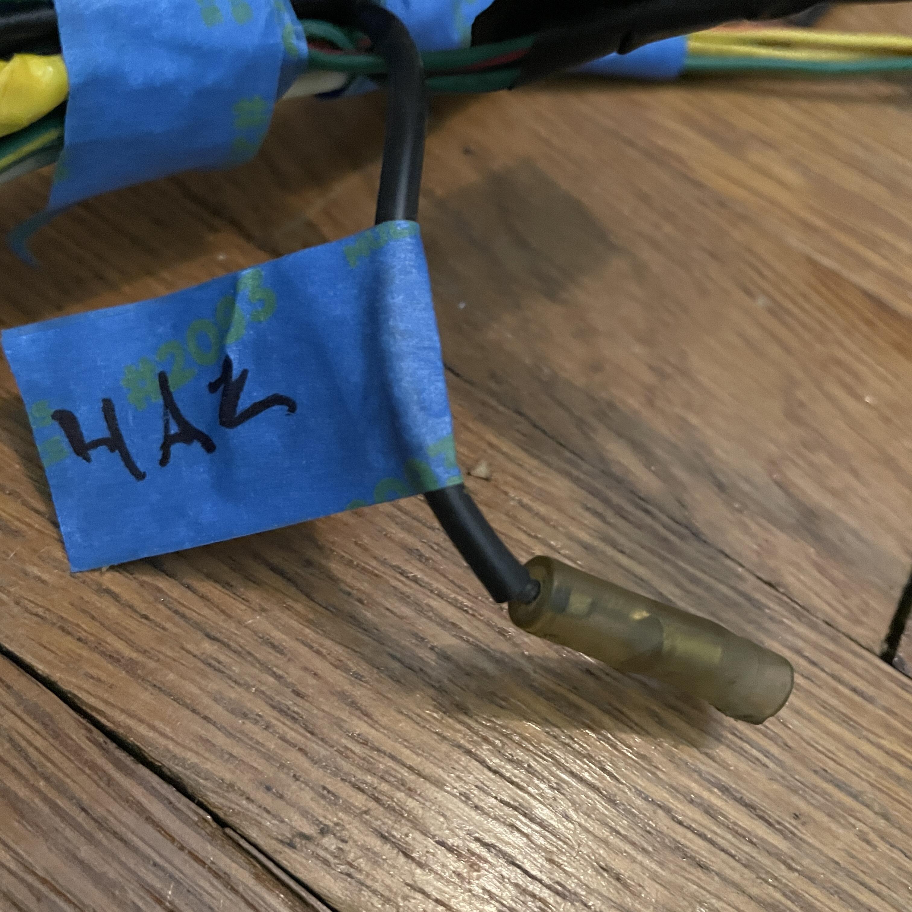
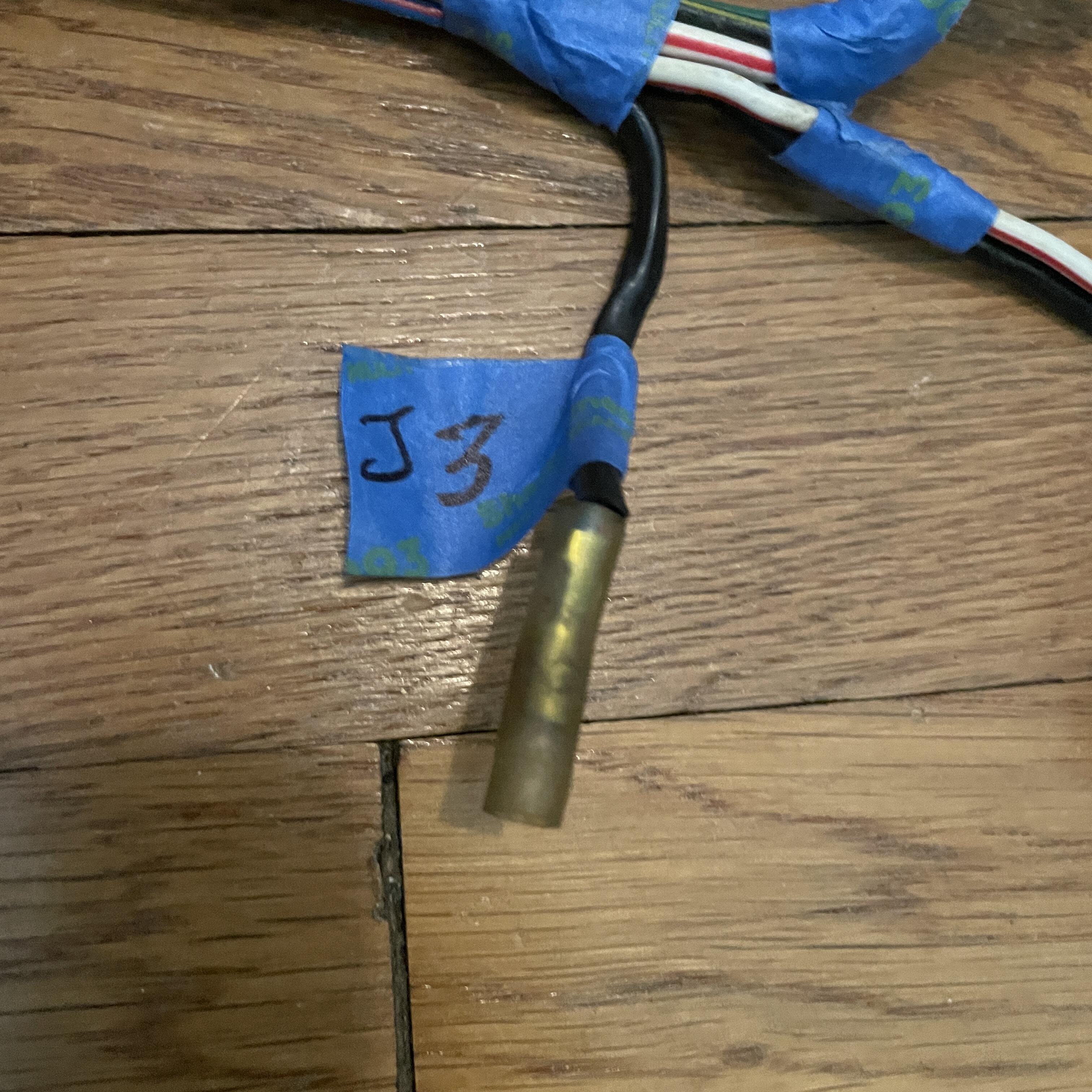
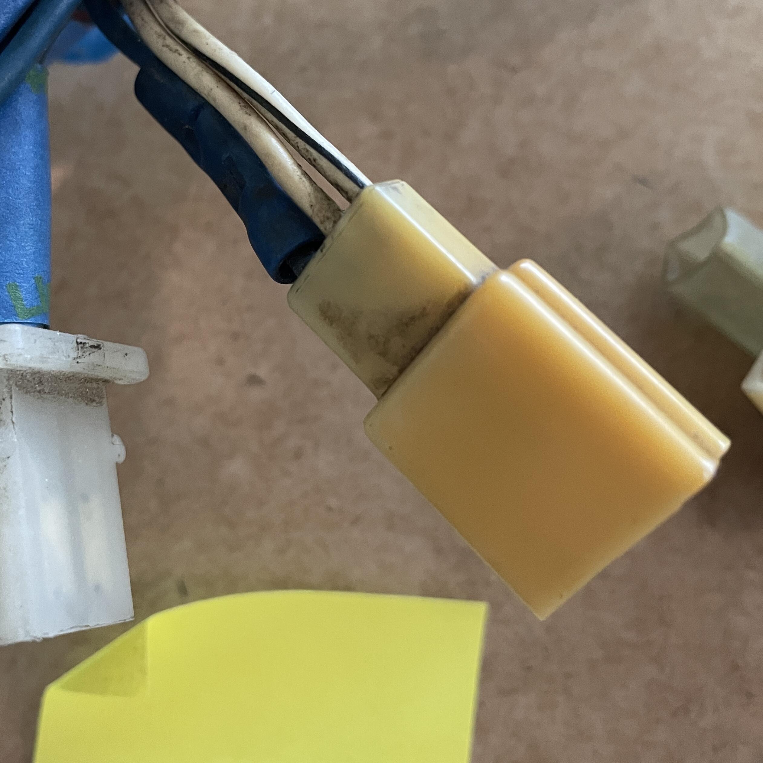
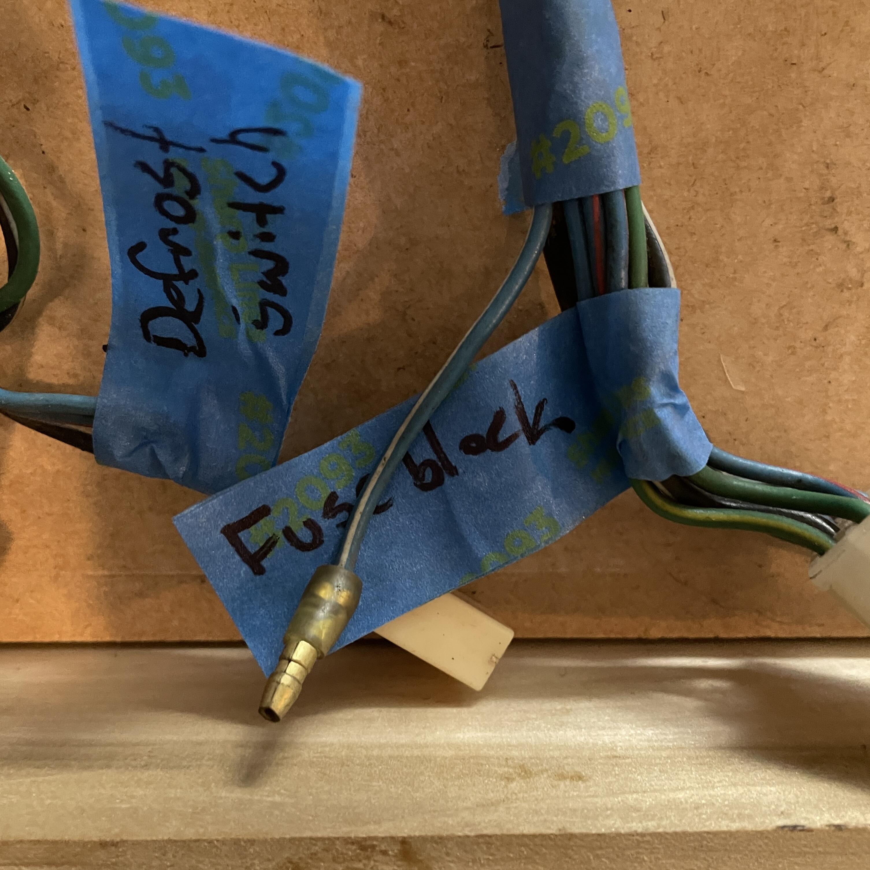
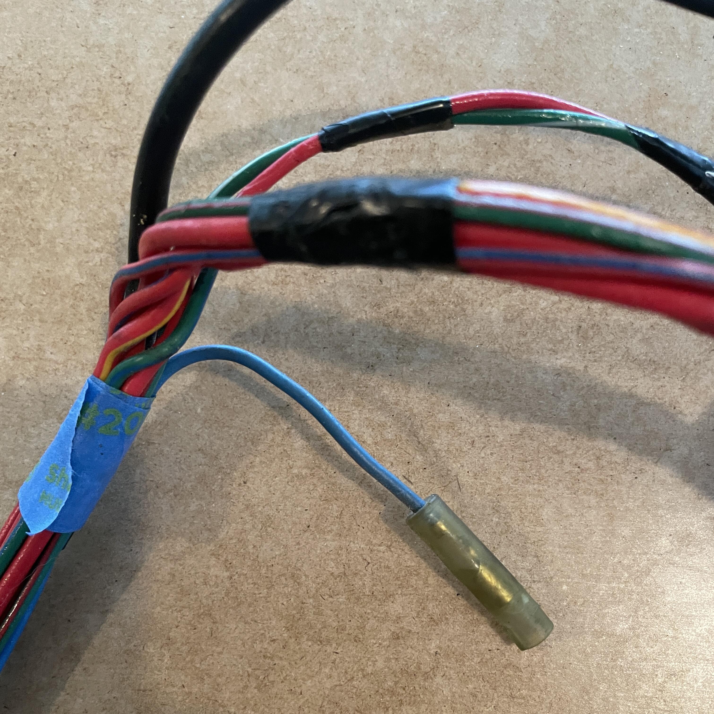
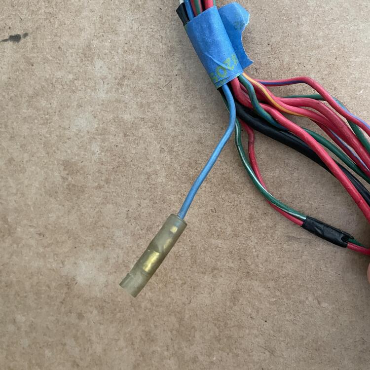
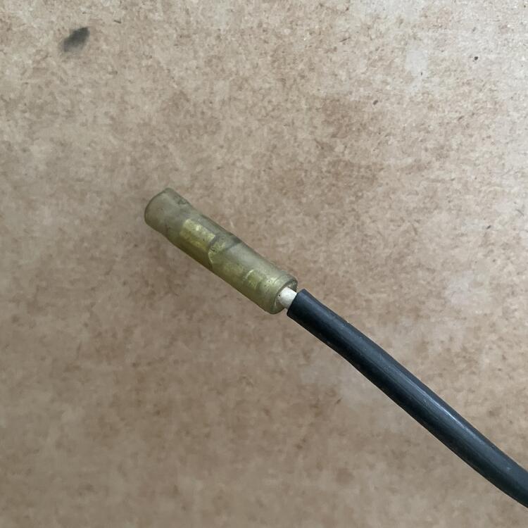
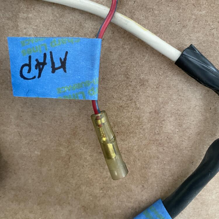
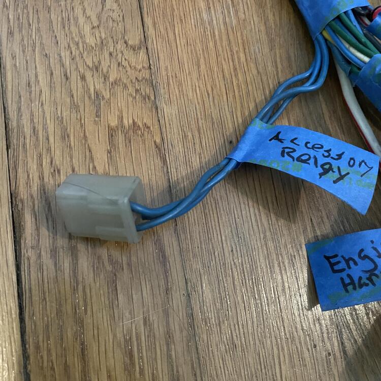
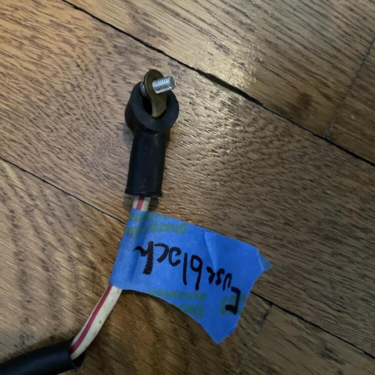
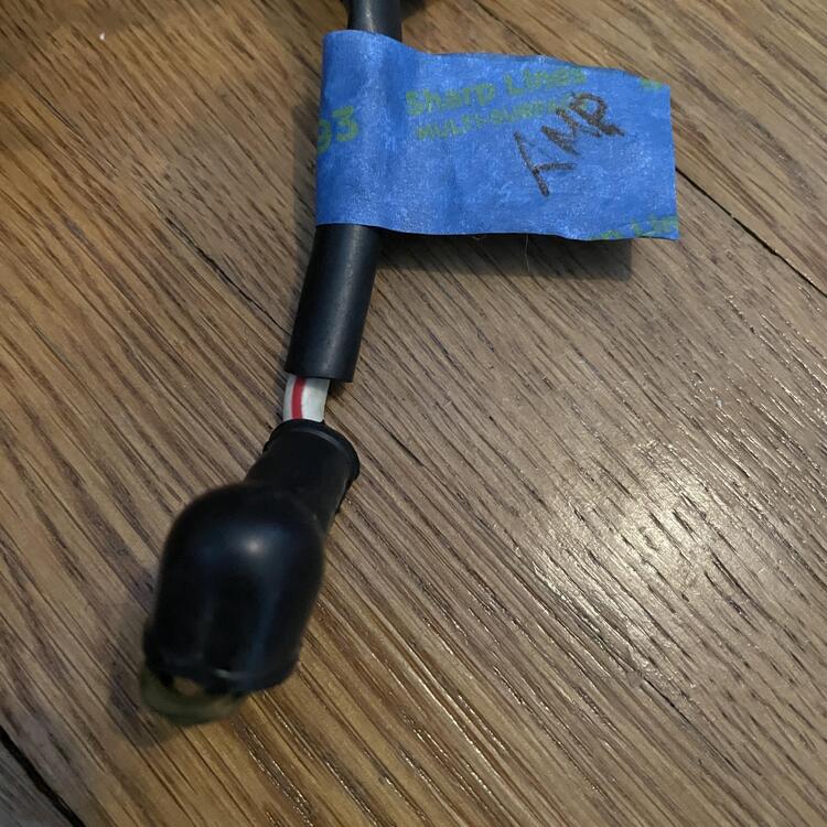
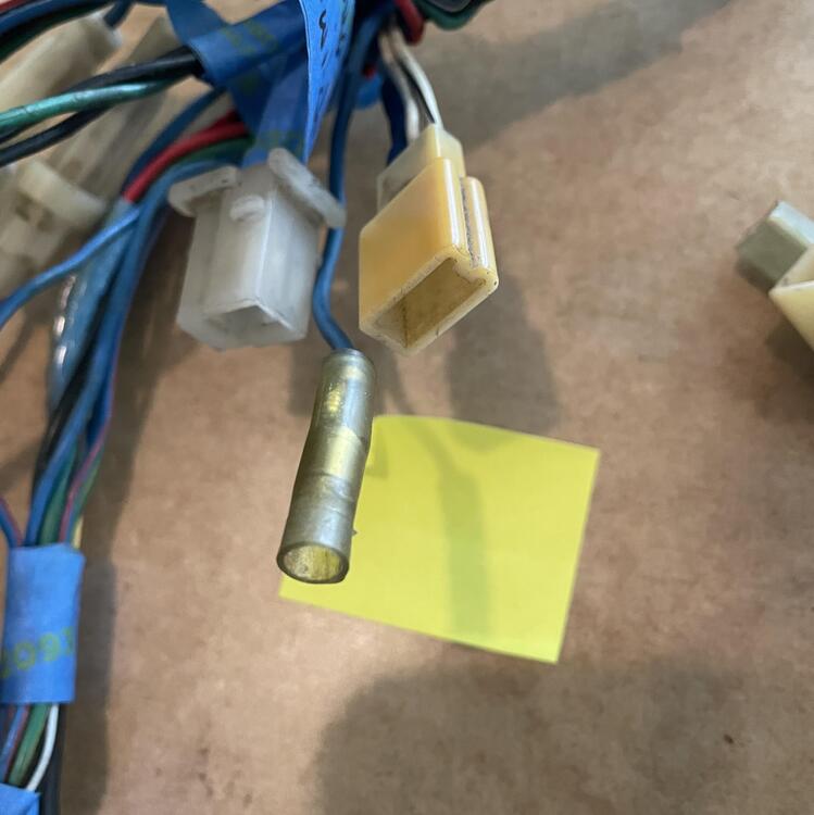
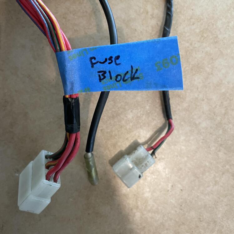
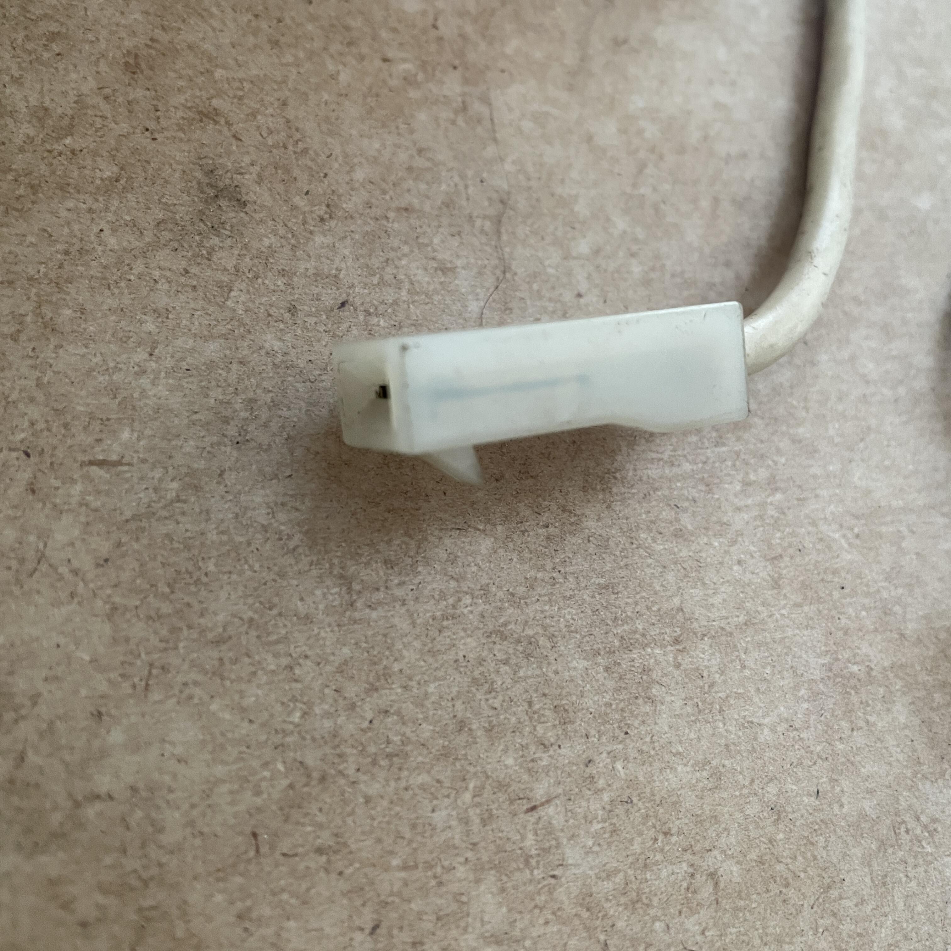
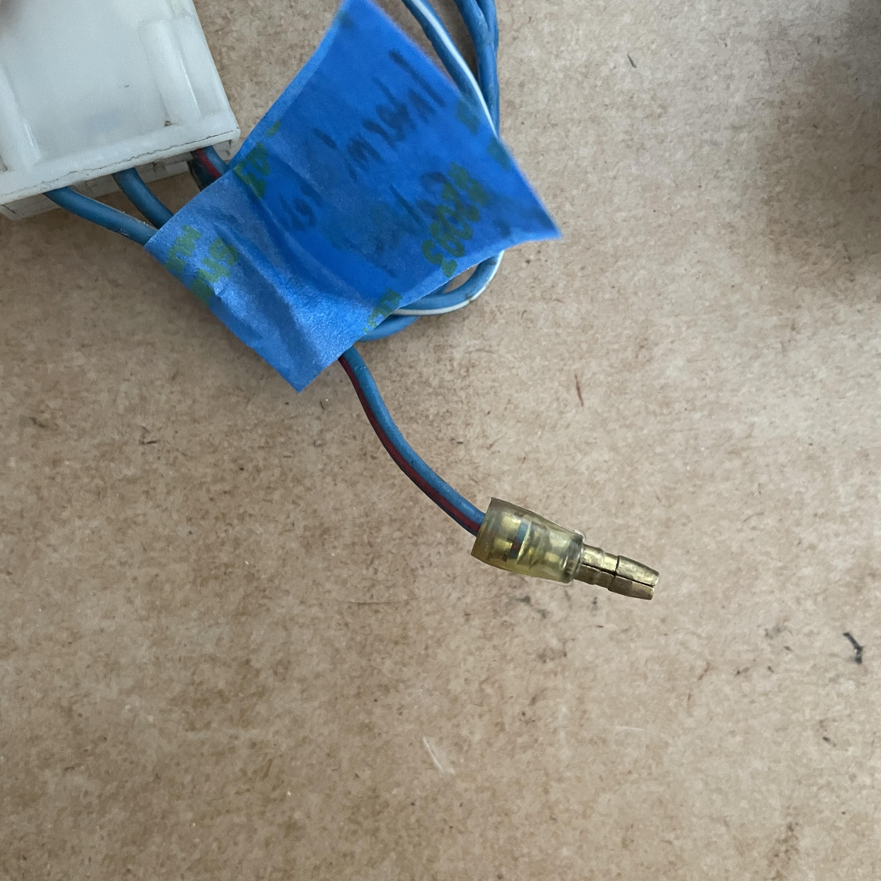
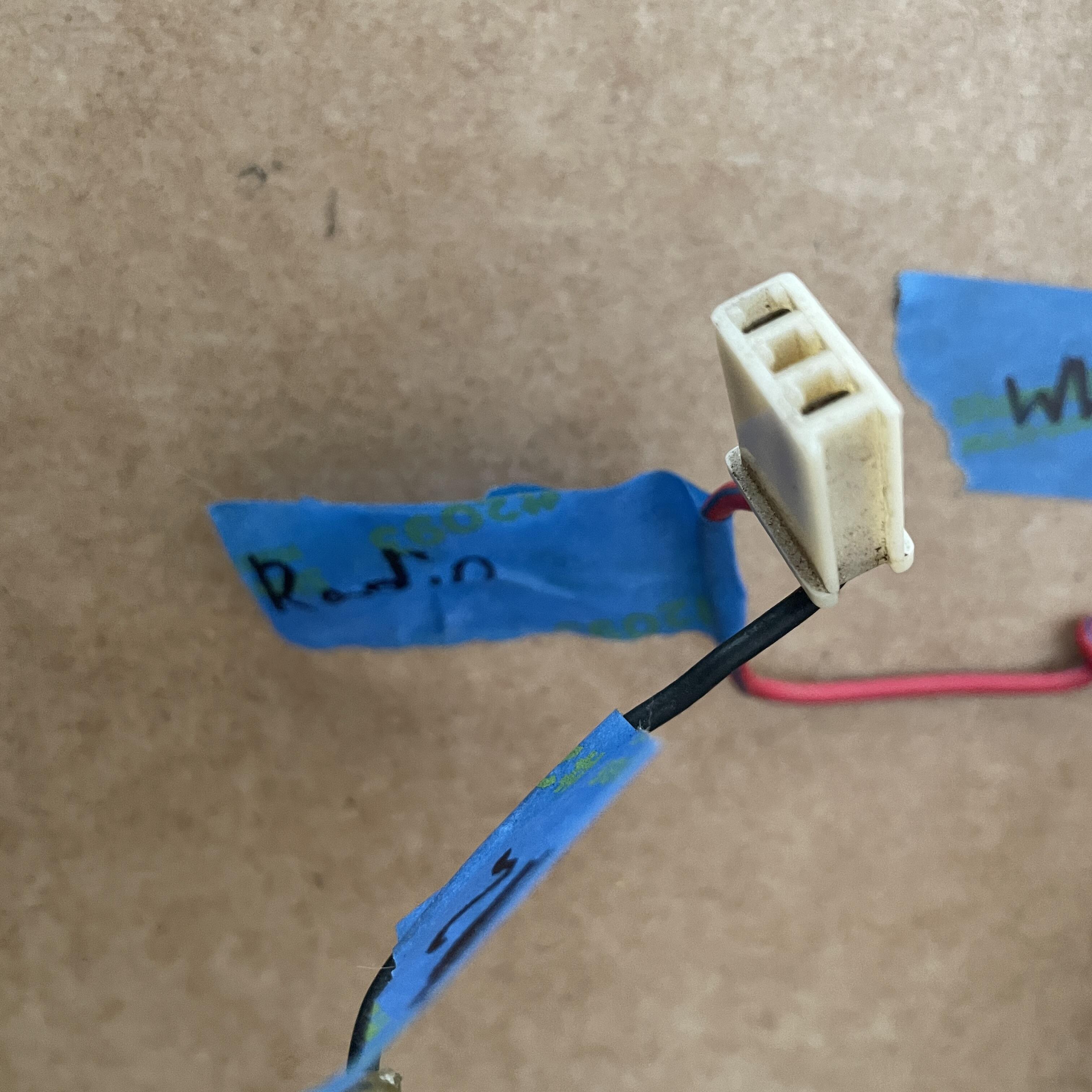
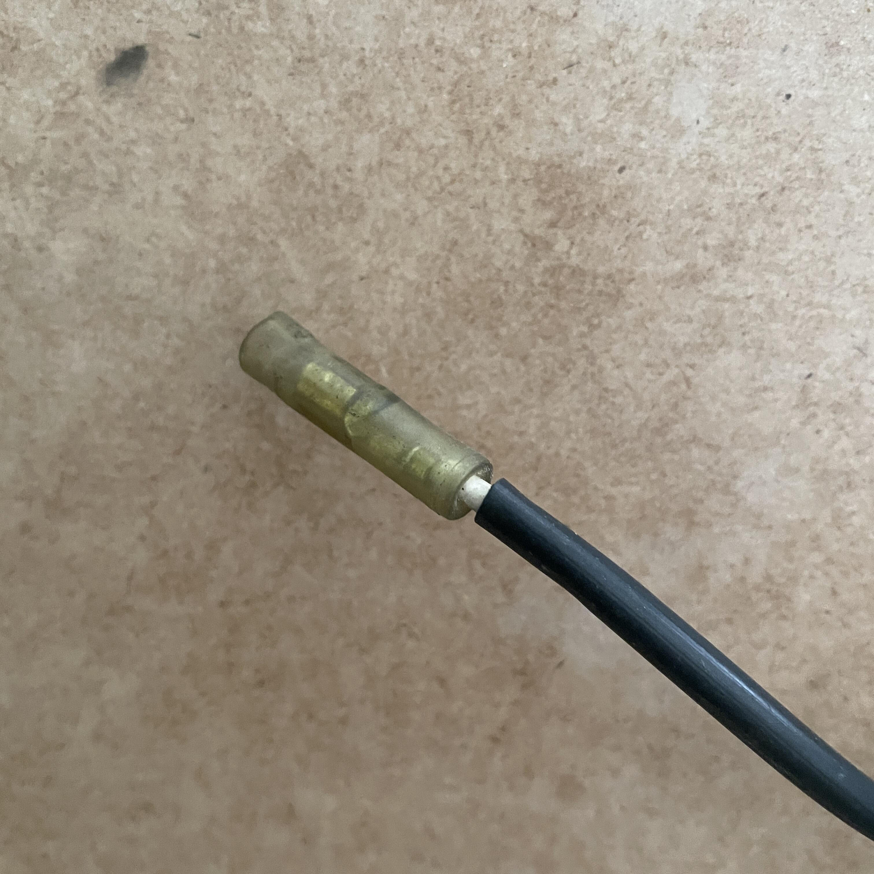
Here you go. It's the one in the black sheath with a female bullet connector pointing to the top of the photo (between the blue wires and the white wire w/ the red stripe).
-
Oh man, this is so helpful! Thank you. I keep forgetting about the speakers. I'll make these updates in my previous post. The position of the blue with red stripe wire at position #7 is right out the big colored connectors. It is spliced to a blue / red wire that goes to the fuse box and another one of the same color for the junction connector that comes out at the ignition switch. It has something to do with the wipers. The wiring diagram shows 3 blue w/ red wires: one going from the ignition switch to the fuse box, one out of the fuse box to the wiper motor, and one from the combination switch and connecting to a yellow / white wire that goes to the wiper fluid bottle.
-
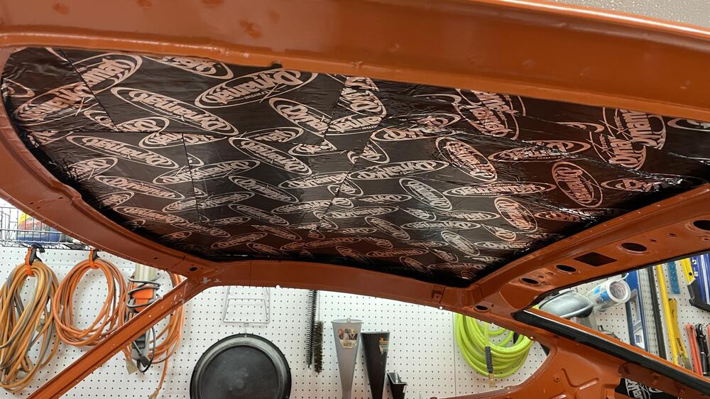
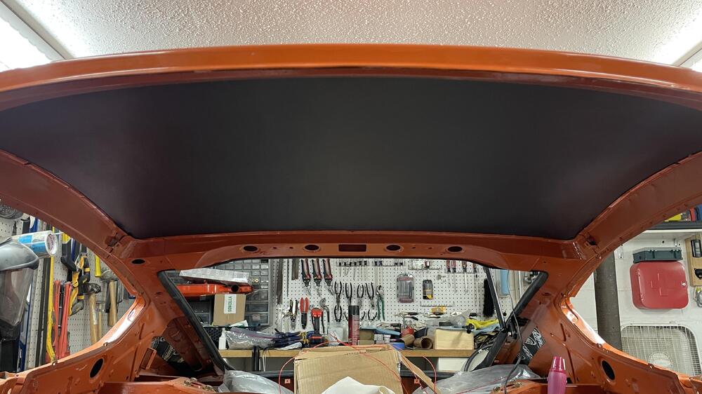
Oh, I should add that I tried just having strips of dynamat, but it showed through the headliner. If you’re going to use any you have to cover the entire roof, and you have to get it on as smooth as possible. The headliner is surprisingly bad at hiding bumps and ridges under it, despite the thick foam backing.
-
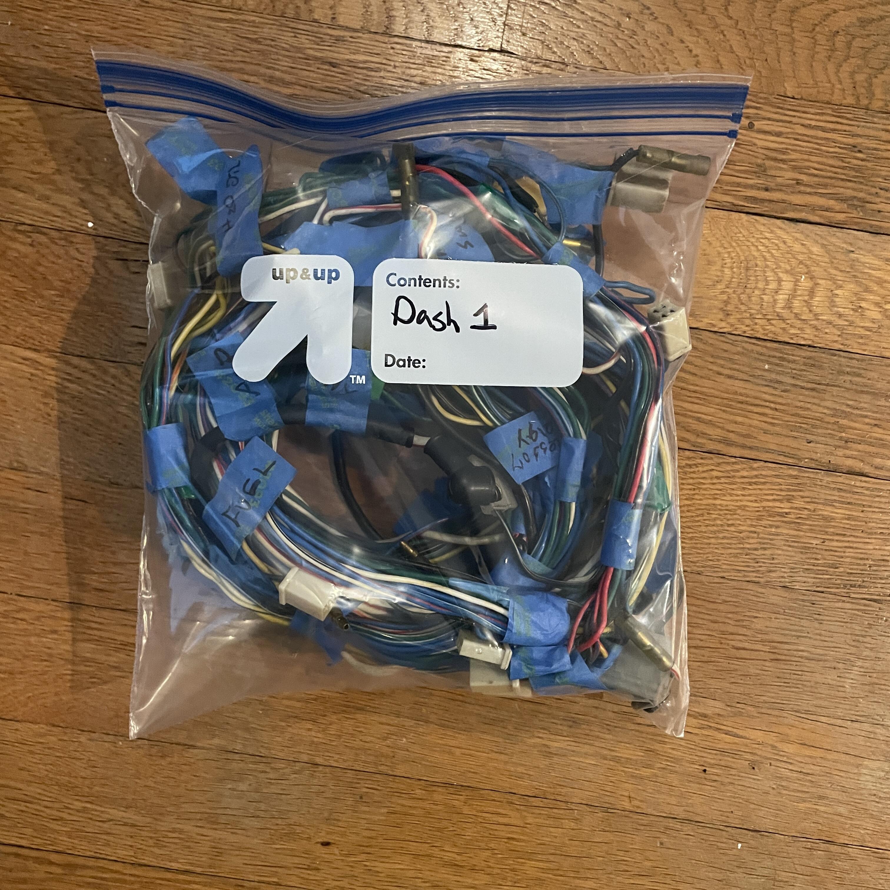
I have a couple of updates: 1. The first half of the dash harness inventory is up in my wiring build thread. Now that that’s in the bag I’m moving on to the second half of the dash harness. 2. I’ve been trying to sneak in small things to help me feel like I’m making progress. This week’s small thing was the head liner. IMG_4916.MOV IMG_4934.MOV Nice and quiet!

-
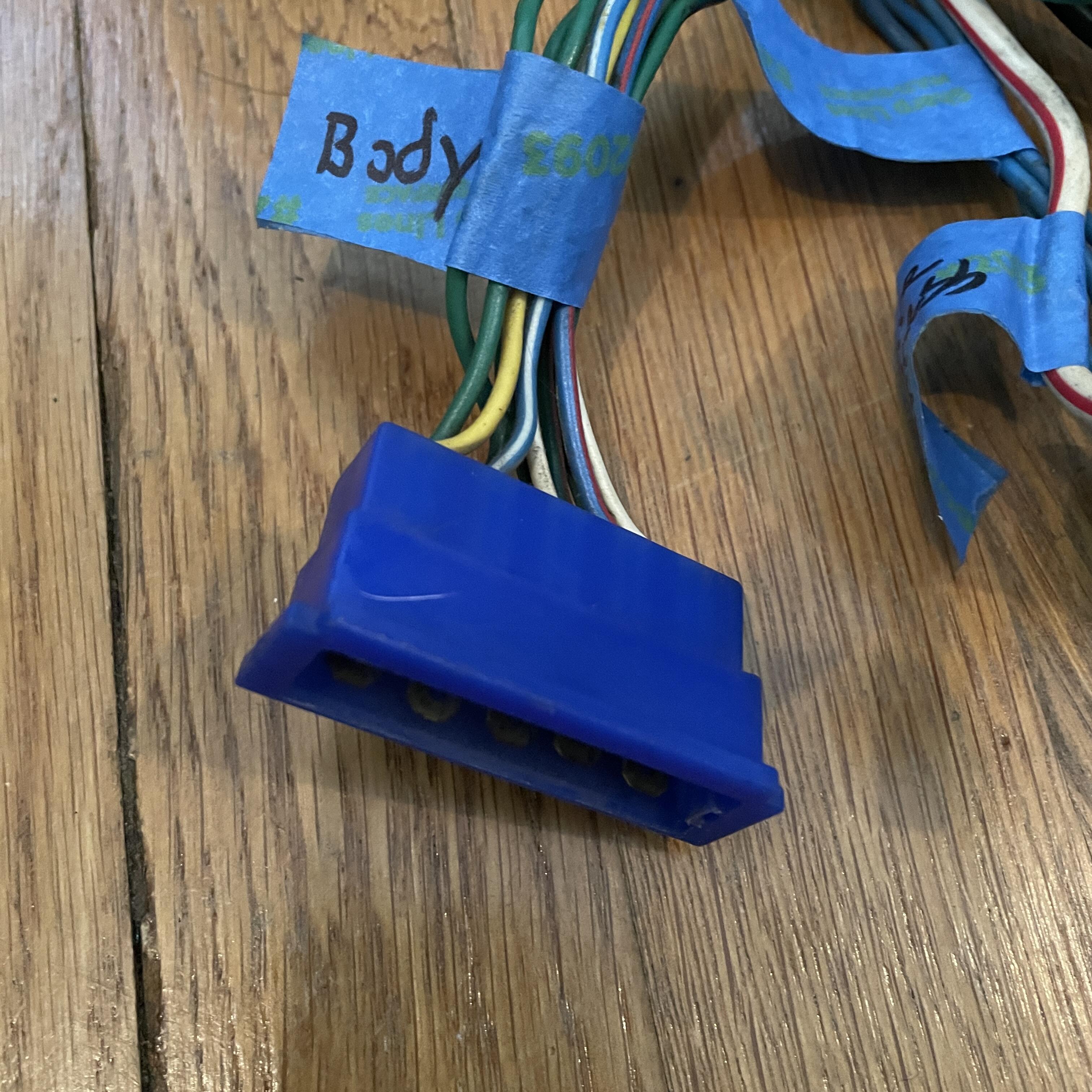
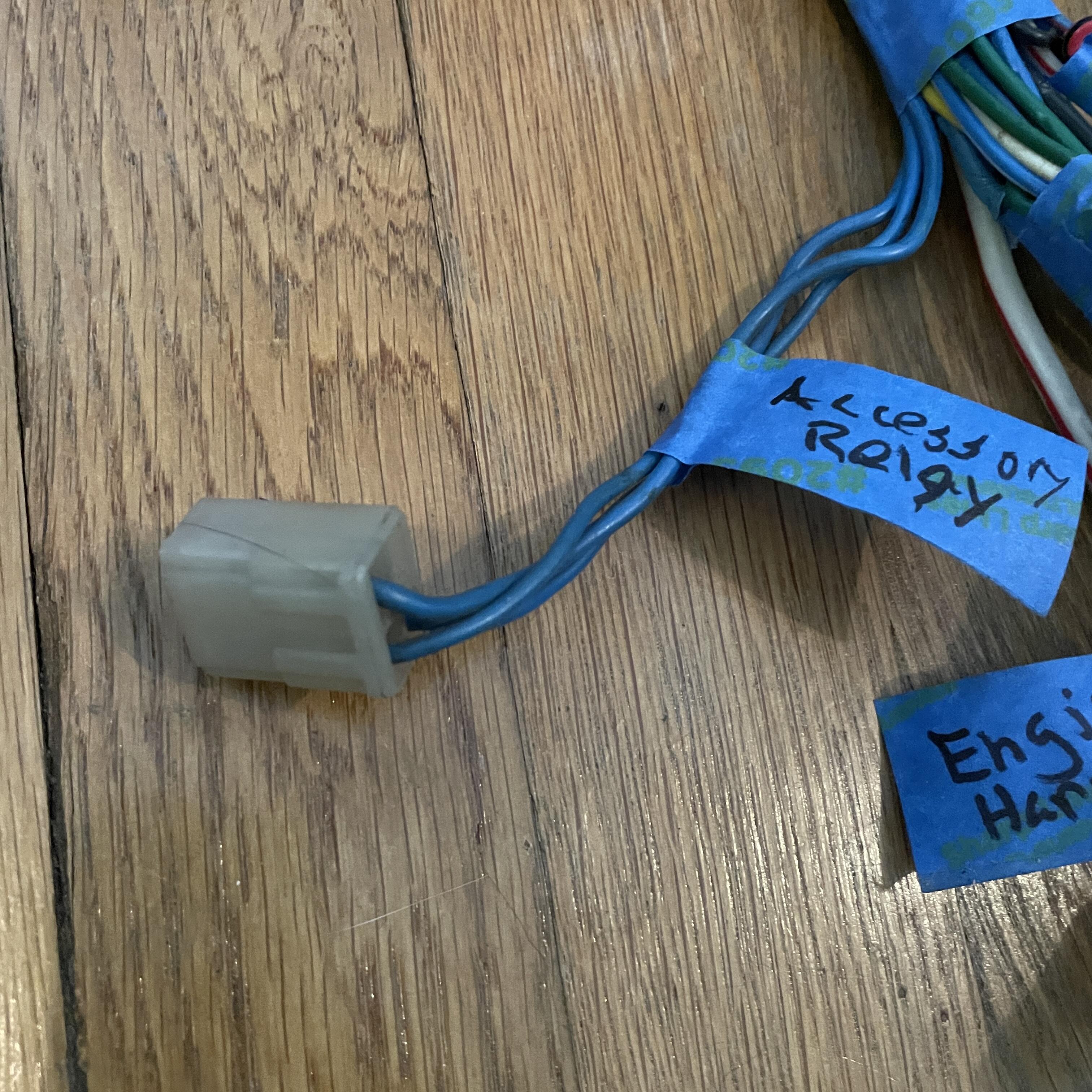
Table Number 3! This table represents half of the dashboard harness for a 1973 240z (PN 24013-M3321). It's… okay. There are three items and a missing wire I can't identify (pink cells) and I am unsure about what I marked as the heater (bright yellow cells), but it's close. The other half will be in the next table. Note: I'll post the wire lengths later. 1973 240z Dashboard Harness (24013-M3321) Inventory Position Component Connector Color Connector Style Connector Image Direction # of Pins # of Wires Diagram Wire Color Sample Wire Color Min. Feet of Wire Needed 1 Body Harness Blue Nylon 10-Prong Male 10 10 White w/ Black White w/ Black [See Speakers & Radio] Blue w/ Red Blue w/ Red [See Power Antenna Switch] White White [See Speakers & Radio] Blue w/ White Blue w/ White [See Power Antenna Switch] Yellow Yellow [See Ammeter & Fuel Gauge] Green Green [See Electric Fuel Pump] Green Green [See Engine Harness D] Green Green [See Engine Harness B] Green w/ Red Green w/ Red 4 (to Yellow Splice) Green w/ Black Green w/ Black 4 (to Gray Splice F) 2 Engine Harness B Green Nylon 10-Prong Male 10 7 Green Green 1 Green Green 4 (to Lt. Blue Splice D) Black w/ Yellow Black w/ Yellow [See Ignition Switch] Green w/ Red Green w/ Red 5 (to Lt. Blue Splice G) Green w/ Black Green w/ Black 4 (to Gray Splice E) Black – Black Black (Heavy) 1 (to Green Splice A) Yellow w/ Red Yellow w/ Red [See Switch Element] – – – – – – 3 Engine Harness D Black White Nylon 10-Prong Male 10 8 Blue w/ Red Blue w/ Red 2 (to Lt. Blue Splice B) Yellow w/ Black Yellow w/ Black [See Water Temperature & Oil Temperature Gauge] Black w/ White Black w/ White 4 (to Green Splice D) Green Green 1 Yellow w/ White Yellow w/ White [See Water Temperature & Oil Temperature Gauge] Green w/ White Green w/ White 4 (to Green Splice F) Black w/ White Black w/ White [See Tachometer] Green w/ White Green w/ White [See Hazard Switch] Blue w/ White Blue w/ White 4 (to Gray Splice C) – – – 4 Engine Harness E White Nylon Male 1 1 White w/ Red White w/ Red (Heavy) 1 (to Gray Splice A) 5 Accessory Relay White Nylon 4 3 Blue Blue 4 (to Red Splice) Blue Blue [See 30-Amp Fuse] – – – Blue Blue [See Heater] 6 Rear Window Electric Defroster Relay White Nylon 4 4 White w/ Red White w/ Red (Thick) [See 20-Amp Fuse] Blue w/ Red Blue w/ Red [See Rear Window Electric Defroster Switch] Black Black 1 (to Green Splice A) Red w/ Blue Red w/ Black (Thick) [See Junction 1A] 7 ? Clear Bullet Female 1 1 Blue w/ Red 2 (to Lt. Blue Splice B) 8 Junction 1A Clear Bullet Male 1 1 Red w/ Black (Thick) 1 Light Blue Splice A N/A N/A N/A N/A 2 Green N/A Green Green Splice A N/A N/A N/A N/A 2 Black N/A Black(Heavy) 2 (to Green Splice B) Light Blue Splice B N/A N/A N/A N/A 2 Blue w/ Red N/A Blue w/ Red Green Splice B N/A N/A N/A N/A 4 Black (Heavy) 4 (to Green Splice D) Black N/A Black Black Light Blue Splice C N/A N/A N/A N/A 4 Green N/A Green Yellow Yellow w/ Red Gray Splice A N/A N/A N/A N/A 2 White w/ Red (Heavy) N/A White w/ Red 9 Junction 1B Clear Bullet Female 1 1 Black 3 Light Blue Splice D N/A N/A N/A N/A 2 Green N/A Green 10 Speakers & Radio White Nylon Male 3 3 White w/ Black White w/ Black 4 White White 4 Blue Blue 1 (from Red Splice) 11 Power Antenna Switch White Nylon Female 3 3 Blue w/ White Blue w/ White 4 Blue Blue 1 (from Red Splice) Blue w/ Red Blue w/ Red 4 12 Heater Clear Bullet Female 1 1 Red Blue 4 13 Buzzer White Nylon Female 3 3 Black Black [See Door Switch LH] Black 3 (to Green Splice C) Green Green 2 (from Lt. Blue Splice D) Green Splice C N/A N/A N/A N/A 2 Black N/A Black 14 30-Amp Fuse White Fuse N/A 2 2 Blue Blue 4 Red Blue X (to Gray Splice B) 15 20-Amp Fuse White Fuse N/A 2 2 White w/ Red White w/ Red 5 White w/ Red White w/ Red 3 (to Gray Splice B) 16 Choke Warning Light White Nylon Male 3 2 Black Black 2 (from Green Splice C) – – – Red w/ Blue Red w/ Blue [See Seatbelt Warning Light] 17 Rear Window Electric Defroster Switch White Nylon Female 3 3 Blue Blue 1 (from Red Splice) Blue w/ Red Blue w/ Red 5 Black Black 3 (from Green Splice C) 18 Electric Fuel Pump White Nylon T 2 2 Black Black w/ White 2 (to Green Splice D) Green Green 5 19 Seatbelt Warning Light White Nylon 4 4 Red Red 2 (to Lt. Blue Splice E) Green Green 3 (from Lt. Blue Splice D) Black Black 3 (from Green Splice C) – Red w/ Blue 5 Red Splice N/A N/A N/A N/A 4 Blue N/A Blue Blue Blue Gray Splice B N/A N/A N/A N/A 3 White w/ Red (Heavy) N/A White w/ Red (Thi)ck Blue Light Blue Splice E N/A N/A N/A N/A 2 Red N/A Green 20 Fuse Box A White Nylon 6 6 Green w/ Yellow Green w/ Yellow 3 (to Gray Splice C) Green w/ White Black w/ White (Thick) 4 (to Green Splice D) Blue w/ Red Blue w/ Red [See Ignition Switch] Blue Blue 1 (to Red Splice) Blue w/ Red Blue w/ Red 3 (from Lt. Blue Splice B) Green Green 2 (from Lt. Blue Splice E) 21 Fuse Box B Black Ring w/ Cap (Nylon in FSM) N/A 1 1 White w/ Red (Heavy) White w/ Red (Heavy) 3 (from Gray Splice B) 22 Fuse Box C Clear Bullet Male 1 1 Blue w/ White Blue w/ White [See Cigar Lighter] Green Splice D N/A N/A N/A N/A 3 Black w/ White N/A Black w/ White Black w/ White (Heavy) 3 (to Green Splice G) Gray Splice C N/A N/A N/A N/A 2 Blue w/ White N/A Green w/ Yellow 23 Clock Clear Bullet Male 1 1 Black Black 1 (to Green Splice E) 24 Map Light Clear Bullet Male 1 1 Black Black 3 (from Green Splice B) 25 Ammeter & Fuel Gauge White Nylon Female 4 3 Black Black 1 (to Green Splice E) – – – Yellow Yellow 4 Yellow w/ Red Yellow w/ Red 3 (from Lt. Blue Splice C) 26 Ammeter Black Ring w/ Cap (Nylon in FSM) N/A 1 1 White w/ Red (Heavy) White w/ Red (Heavy) 2 (from Gray Splice D) Gray Splice D N/A N/A N/A N/A 3 White w/ Red (Heavy) 3 (from Gray Splice A) White w/ Red (Heavy) N/A White w/ Red (Heavy) Gray Splice E N/A N/A N/A N/A 3 Green w/ Black N/A Green w/ Black Green w/ Black Green Splice E N/A N/A N/A N/A 2 Black (Heavy) N/A Black Light Blue Splice F N/A N/A N/A N/A 3 Green w/ Red N/A Green w/ Red Green w/ Red 27 Water Temperature & Oil Temperature Gauge White Nylon Female 4 4 Yellow w/ Black Yellow w/ Black 4 Black Black 4 (from Green Splice E) Yellow w/ White Yellow w/ White 4 Yellow Yellow X (from Lt. Blue Splice C) Light Blue Splice G N/A N/A N/A N/A 3 Green N/A Green Green w/ Yellow 28 Cigar Lighter Black Spade Male 1 1 Black Black 2 (to Green Splice G) Clear Bullet Female 1 1 Blue w/ White Blue w/ White 4 29 Hazard Switch A White Nylon Female 3 3 Green w/ Yellow Green w/ Yellow [See Brake Light Switch] White w/ Black White w/ Black 2 (from Gray Splice F) White w/ Red White w/ Red 1 (to Yellow Splice) 30 Hazard Switch B White Nylon Female 6 6 Green Green 1 (from Lt. Blue Splice G) Green Green [See Turn Signal Flasher Switch] Green w/ Yellow Green w/ Yellow 3 (from Gray Splice C) Green w/ Black Green w/ Black 2 (from Gray Splice E) Green w/ Red Green w/ Red 3 (from Lt. Blue Splice F) Green w/ White Green w/ White 4 31 Hazard Switch C Clear Bullet Female 1 1 Black Black 2 (to Green Splice G) Gray Splice F N/A N/A N/A N/A 2 Green w/ Black N/A White w/ Black Yellow Splice N/A N/A N/A N/A 2 Green w/ Red N/A White w/ Red 32 Tachometer White Nylon Female 4 4 Black Black 2 (to Green Splice G) Black w/ White Black w/ White 5 Green w/ White Green w/ White 2 (to Green Splice F) Green Green (Spliced to Red w/ Blue) 3 (from Lt. Blue Splice G) 33 Turn Signal Indicator Light LH Black Blulb N/A 1 1 Green w/ Red Green w/ Red 2 (from Lt. Blue Splice F) 34 Turn Signal Indicator Light RH Black Blulb N/A 1 1 Green w/ Black Green w/ Black 2 (from Gray Splice E) 35 Switch Element White Nylon Female 3 2 Yellow Yellow 2 (to Green Splice H) – – – Yellow w/ Red Yellow w/ Red 5 Green Splice F N/A N/A N/A N/A 2 Green w/ White N/A Green w/ White Green Splice G N/A N/A N/A N/A 4 Black (Heavy) N/A Black Black Black Green Splice H N/A N/A N/A N/A 2 Black w/ White (Thick) N/A Yellow 36 Brake Indicator Light Black Bulb N/A 2 2 – Green w/ Yellow 2 (from Lt. Blue Splice G) Yellow w/ Blue Yellow w/ Green [See Hand Brake Junction] 37 Hand Brake Junction Clear Bullet Female 1 1 Yellow w/ Green 1 38 Door Switch LH Clear Bullet Female 1 1 Black Black 6 39 Turn Signal Flasher Switch White Nylon Female 2 2 Green Green 6 White White [See Combination Switch B] 40 Brake Light Switch Clear Bullet Female 1 1 Green w/ Yellow Green w/ Yellow 6 Clear Bullet Female 1 1 Green w/ Yellow Green w/ Yellow [See Turn Signal Switch] 41 Turn Signal Switch White Nylon Female 6 5 Green w/ Yellow Green w/ Yellow 6 Green w/ Red Green w/ Red 2 (from Lt. Blue Splice G) Green w/ Black Green w/ Black 3 (from Gray Splice E) – – – Green w/ Black Green w/ Black 3 (from Gray Splice F) Green w/ Red Green w/ Red 3 (from Yellow Splice) Gray Splice G N/A N/A N/A N/A 3 White w/ Red (Heavy) 3 (from Gray Splice D) White w/ Red (Heavy) N/A White w/ Red (Heavy) 42 Ignition Switch White Nylon Female 6 5 – – – Blue w/ Red Blue w/ Red 6 White w/ Red White w/ Red (Double Thick) 2 (from Gray Splice G) Black w/ Yellow Black w/ Yellow (Thick) 6 Black w/ White Black w/ White (Thick) 3 (from Green Splice H) Green w/ White Green w/ White 3 (from Green Splice F) 43 Junction 1C Clear Bullet Female 1 1 Blue w/ Red 6 (from Lt. Blue Splice B) 44 Combination Switch A Black Spade (Large) Male 1 1 Black Black (Heavy) 2 (from Green Splice G) 45 Combination Switch B Black Spade Male 1 1 White White 6 46 Combination Switch C Clear Bullet Female 1 1 White w/ Red White w/ Red (Thick) 2 (from Gray Splice G)


-
Yeah, these are the threads that informed my previous comments. I’m glad you pointed that out, though, so I know the symptom to watch for. I am pretty sure this is a five-speed lever and doesn’t need to be ground for a few reasons, not least of which because it matches the truck lever that came with the transmission.
-
Time for a side quest: In my continuing saga to clear my basement and get this Lego kit of a car together, I was cleaning the shift lever that came with it. Yes, it was a loose part in a cardboard box when I got it. Not, I didn’t get any info with it. From what I can tell this is a five speed lever. The piece below the pin hole is 37.5 mm from the end of the ball to the crease where the lever becomes sort of spherical: It’s identical to the long lever that came in my transmission, which is a five speed out of a truck. I think I’m good to go, but if anyone sees a red flag here, let me know. This week has had a string of happy accidents, and the PO’s good up here worked out for me if my research is correct.

-
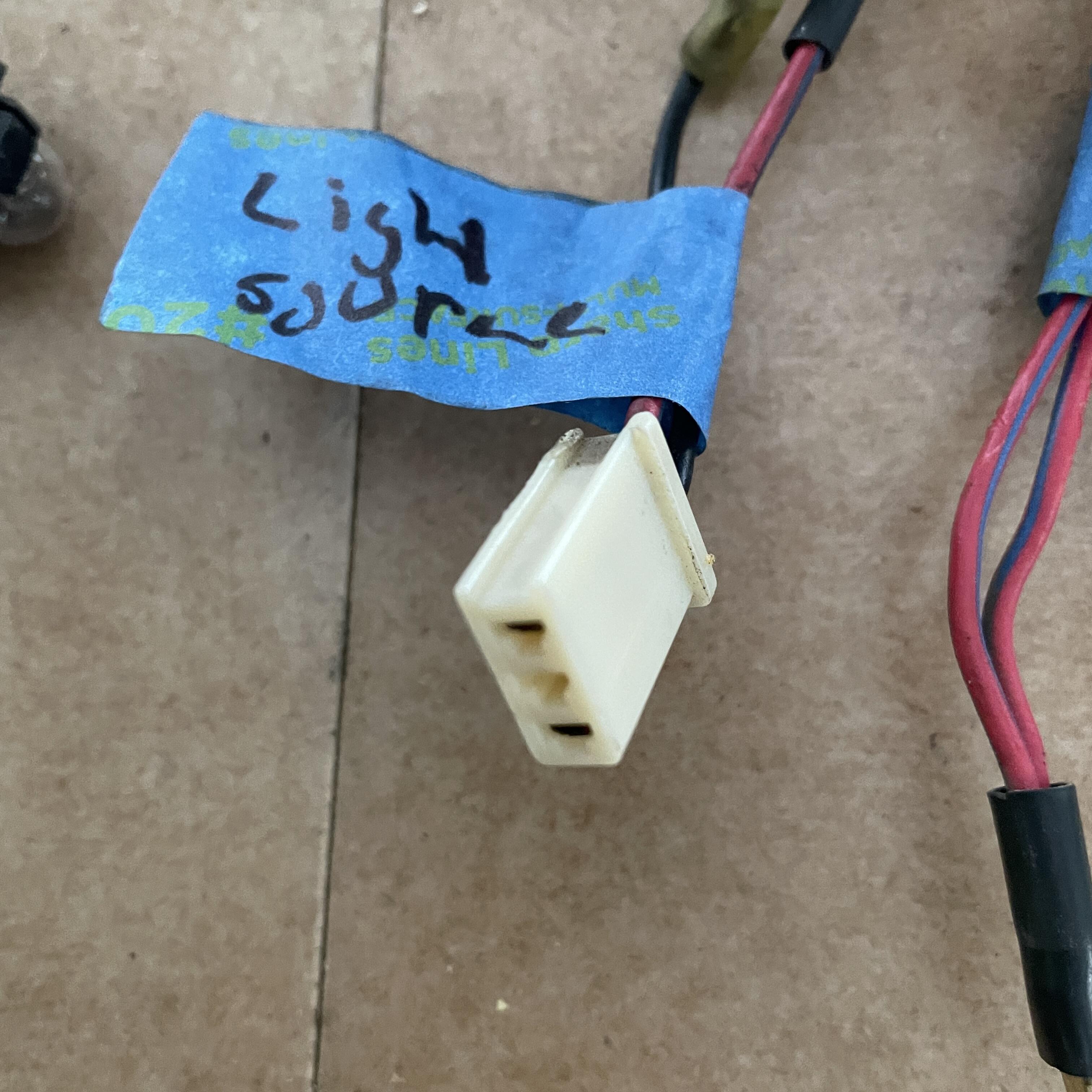
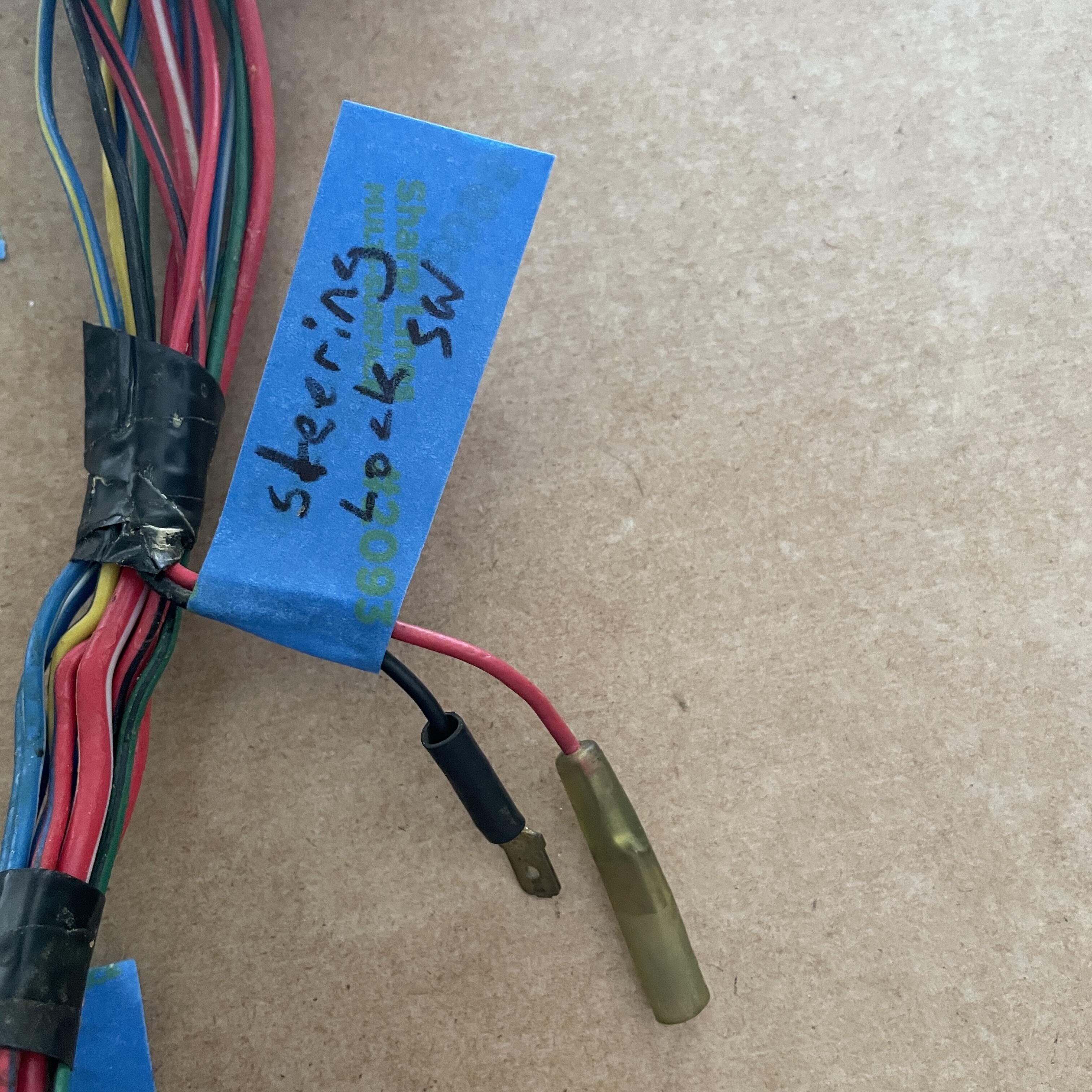
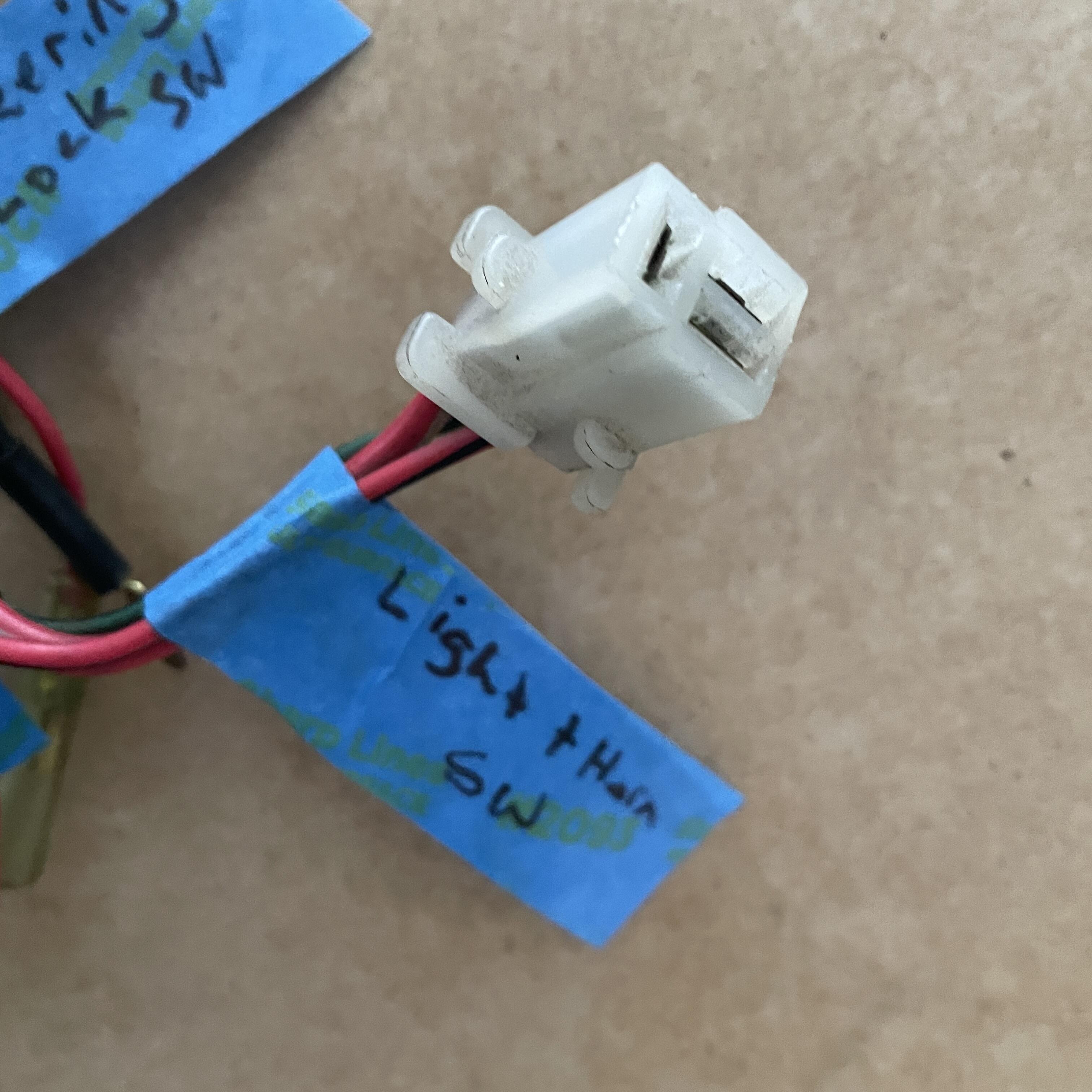
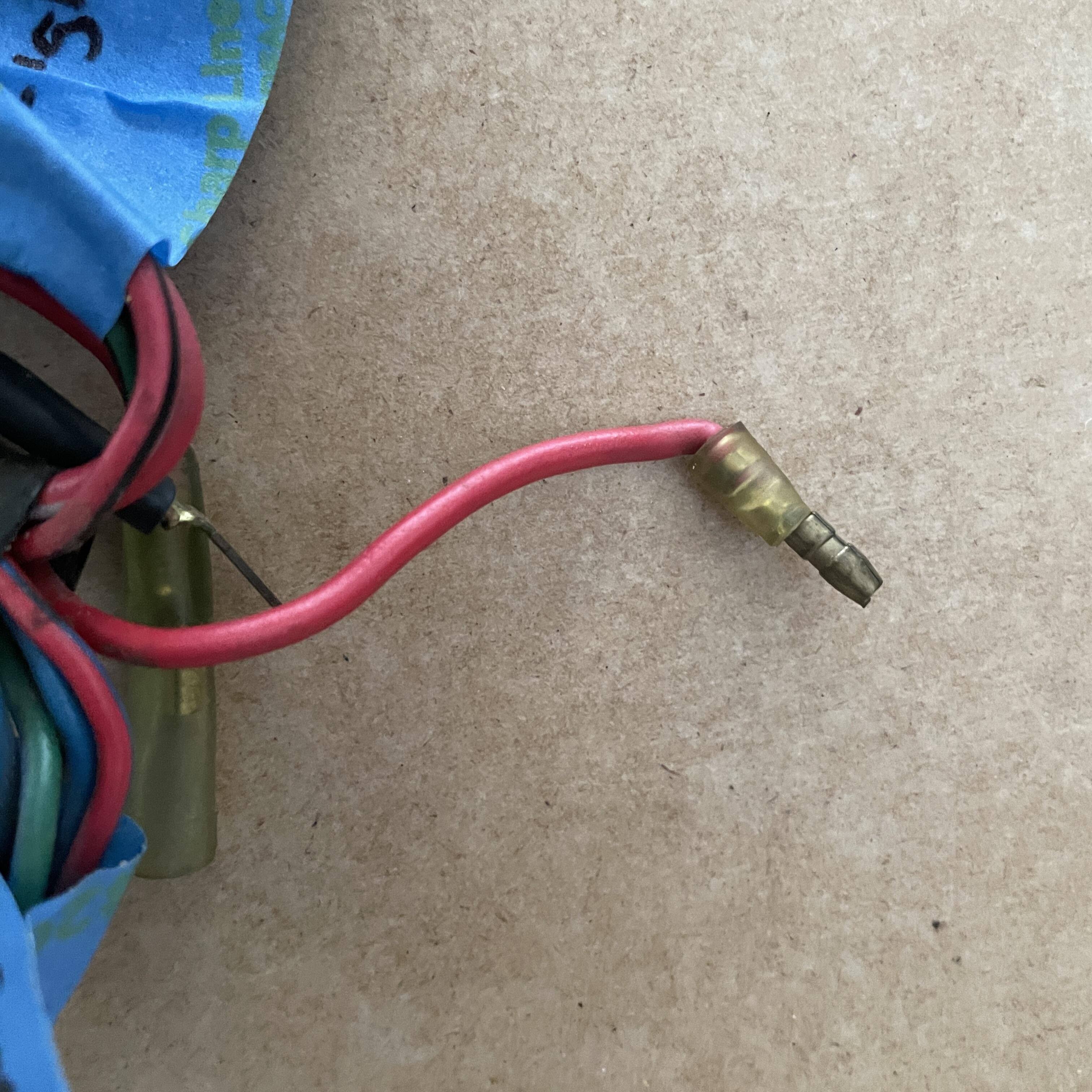
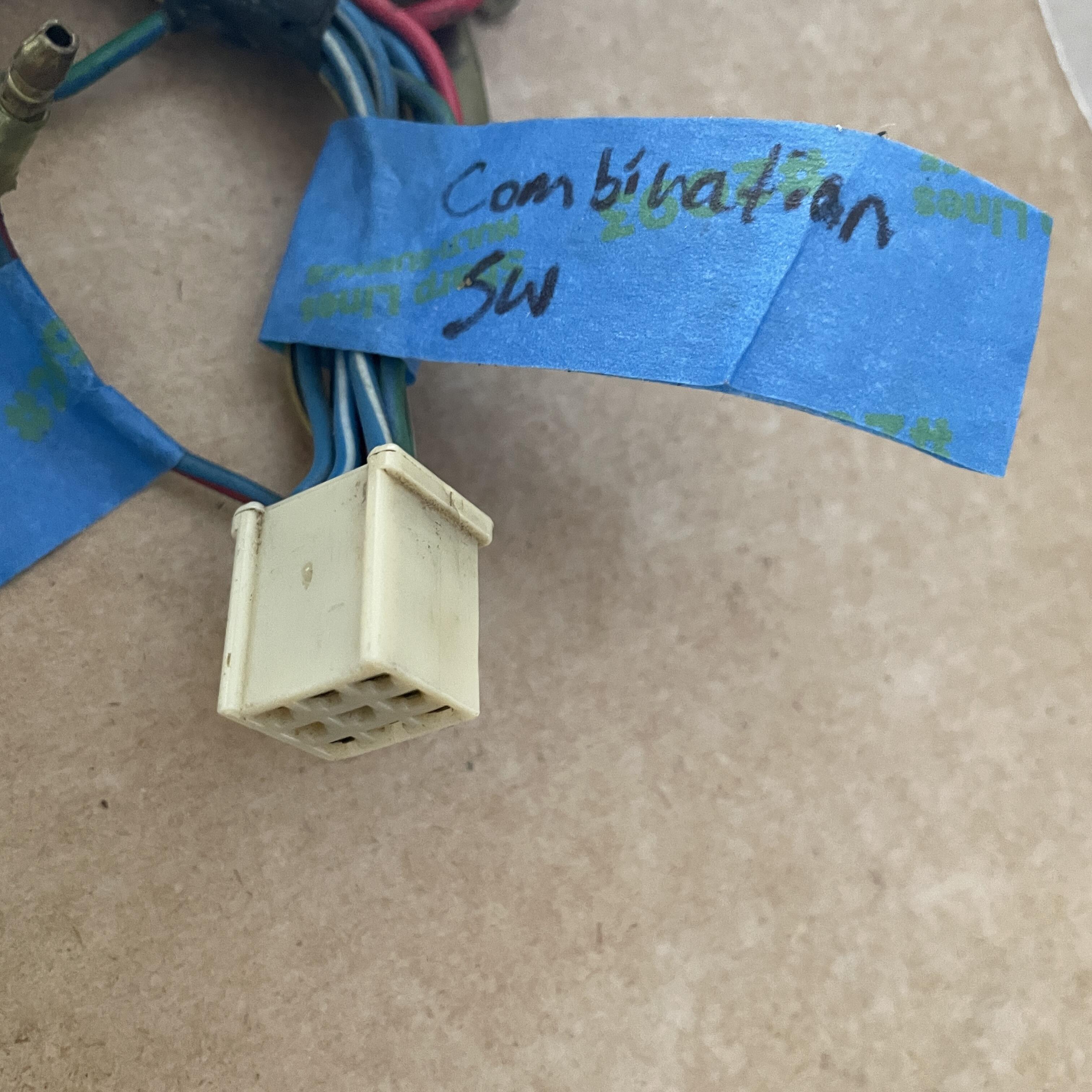
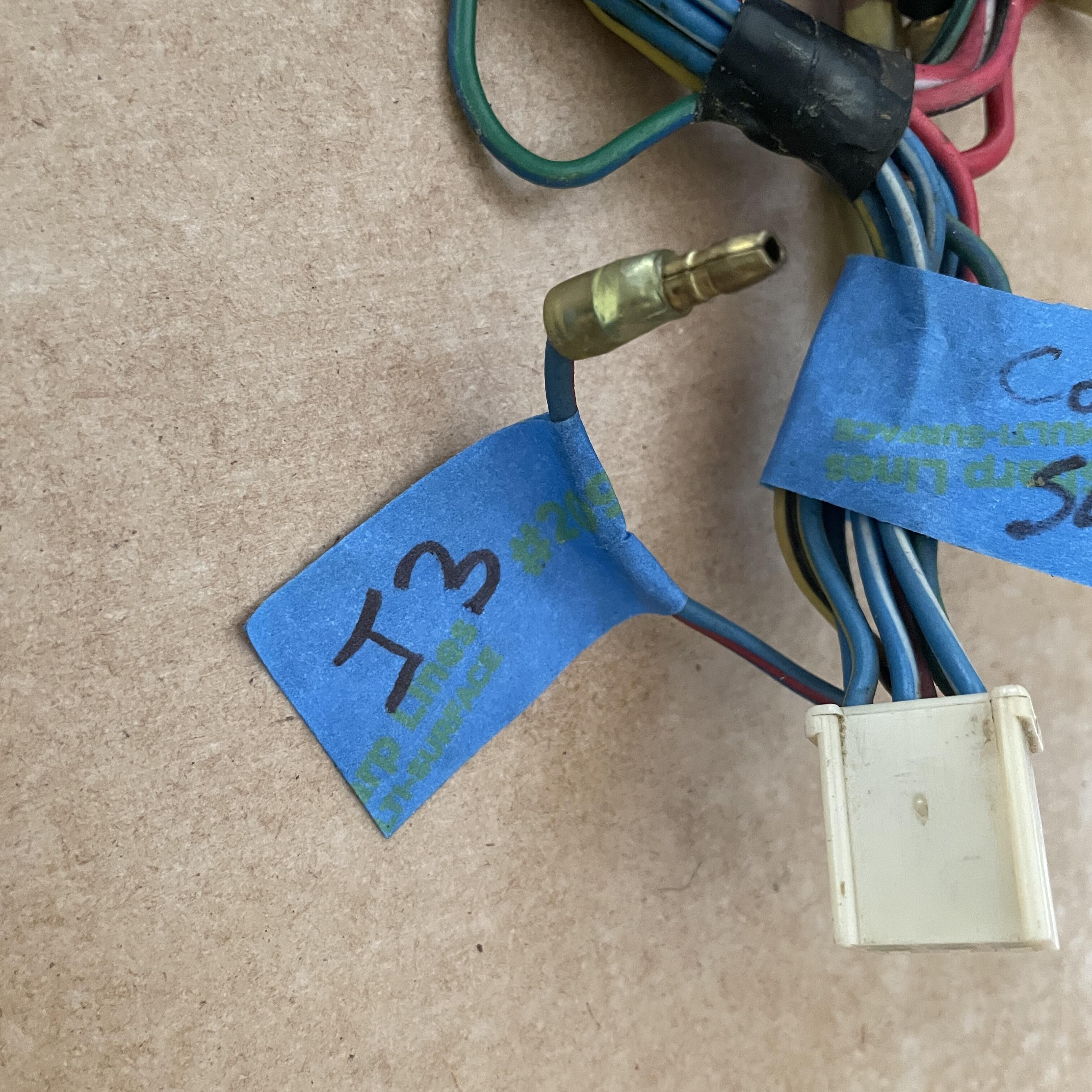
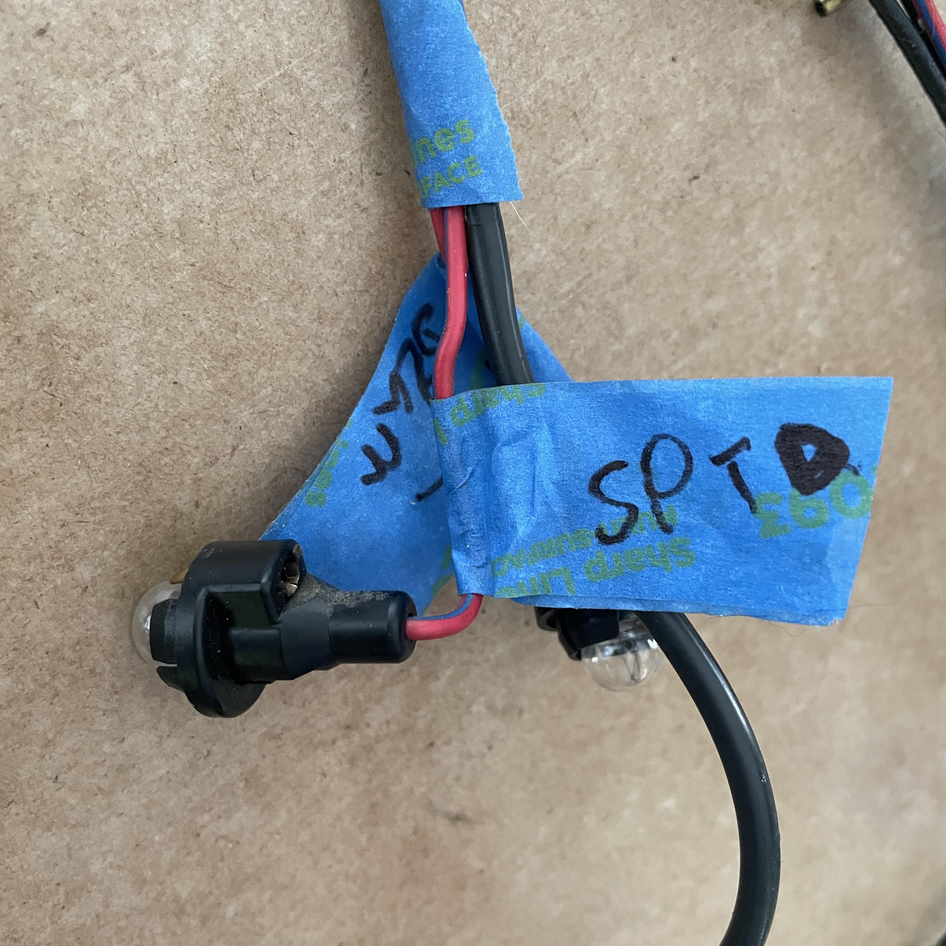
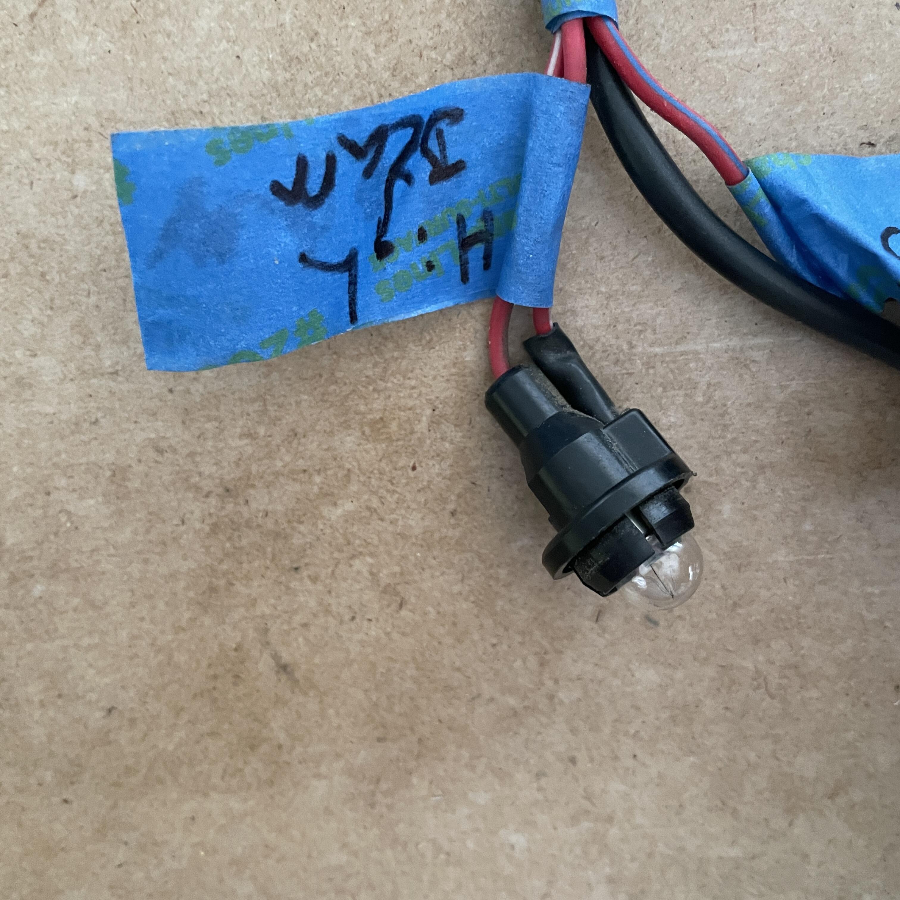
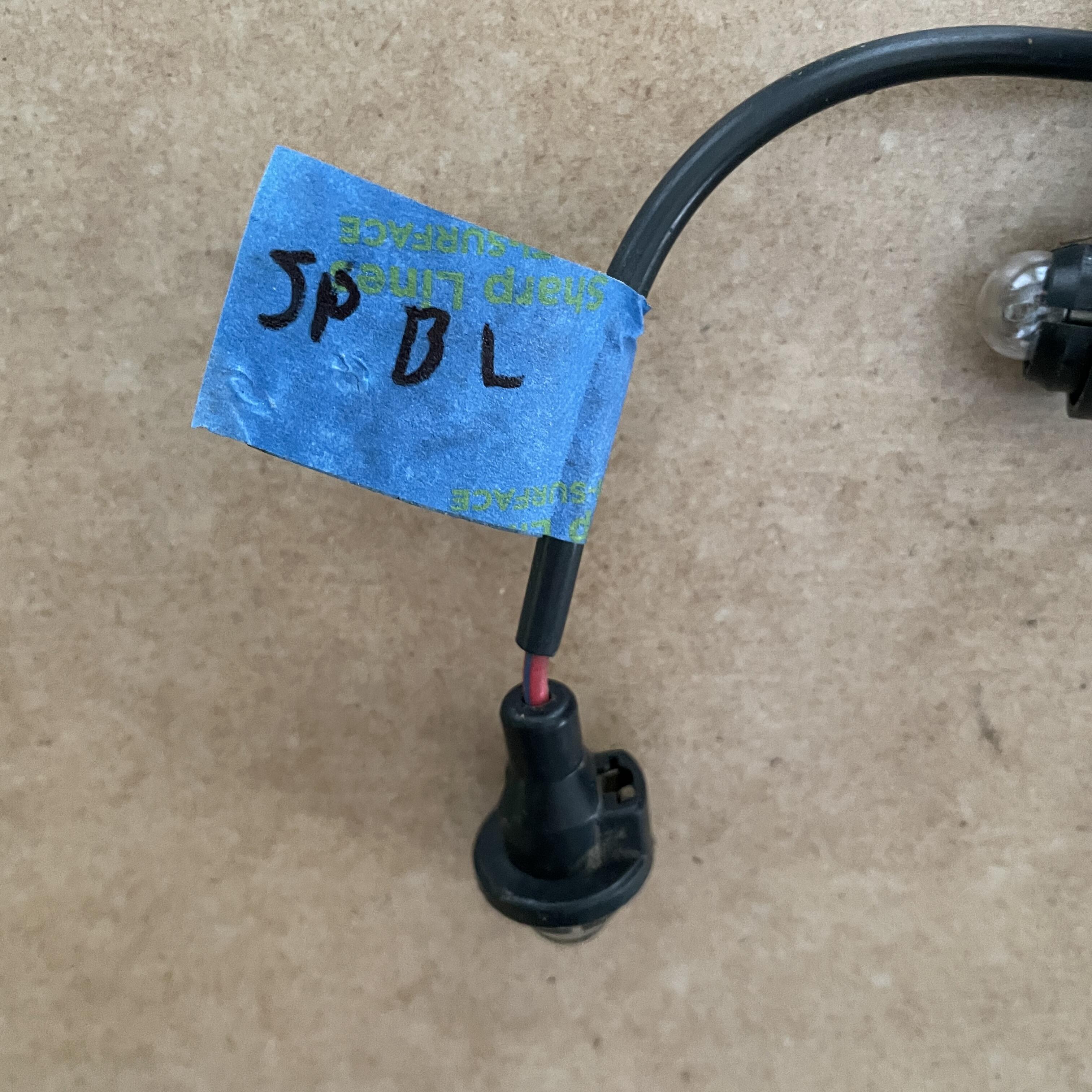
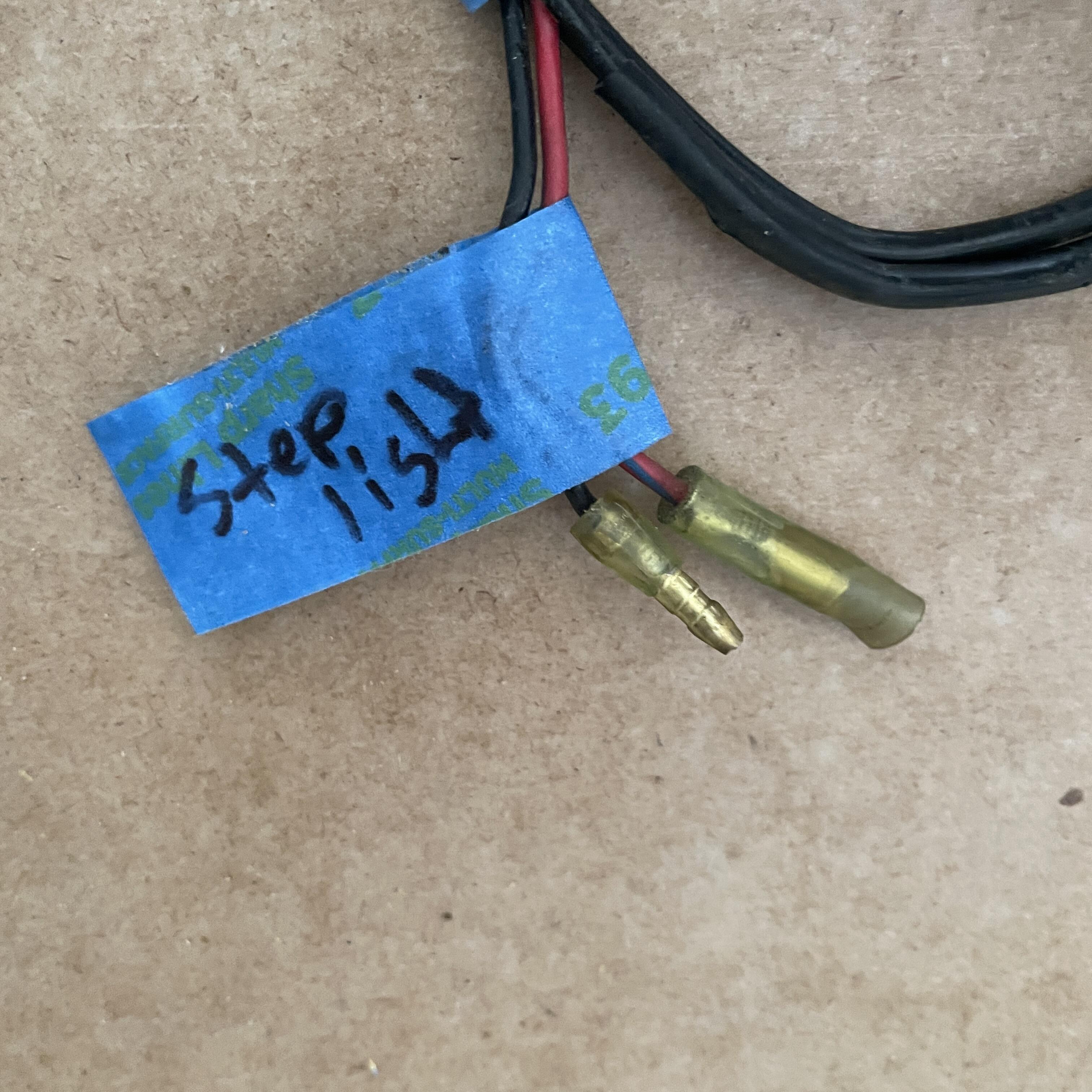
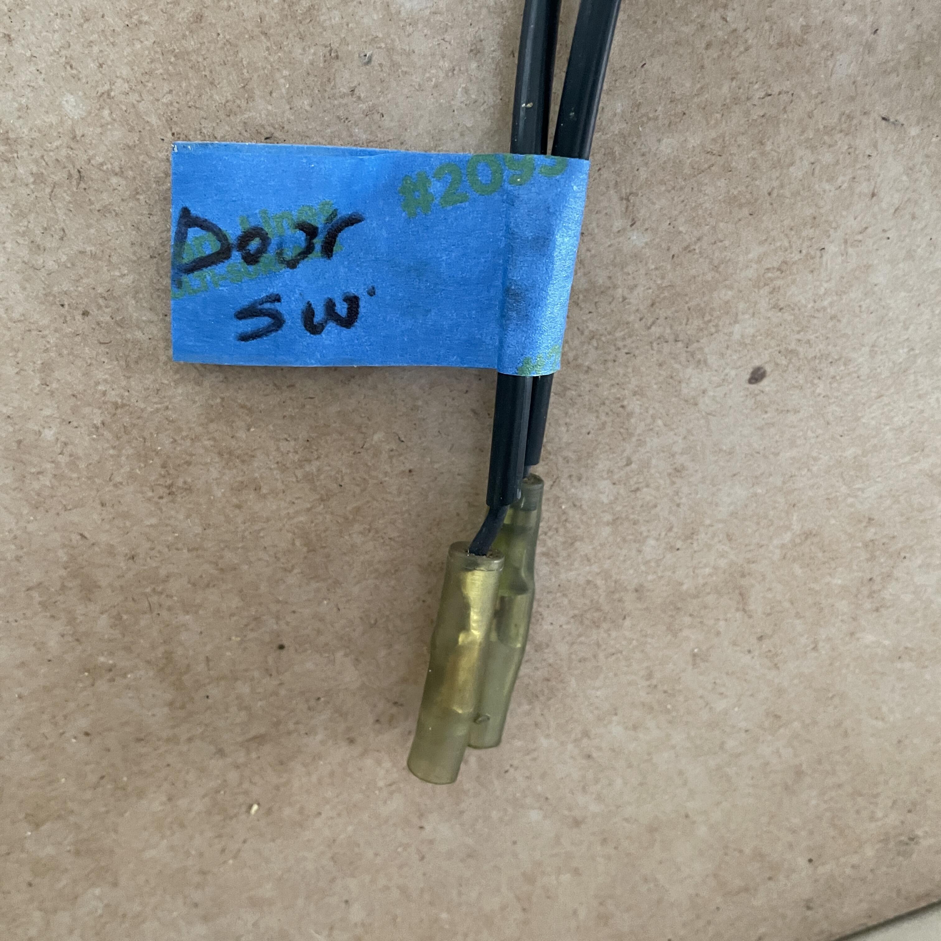
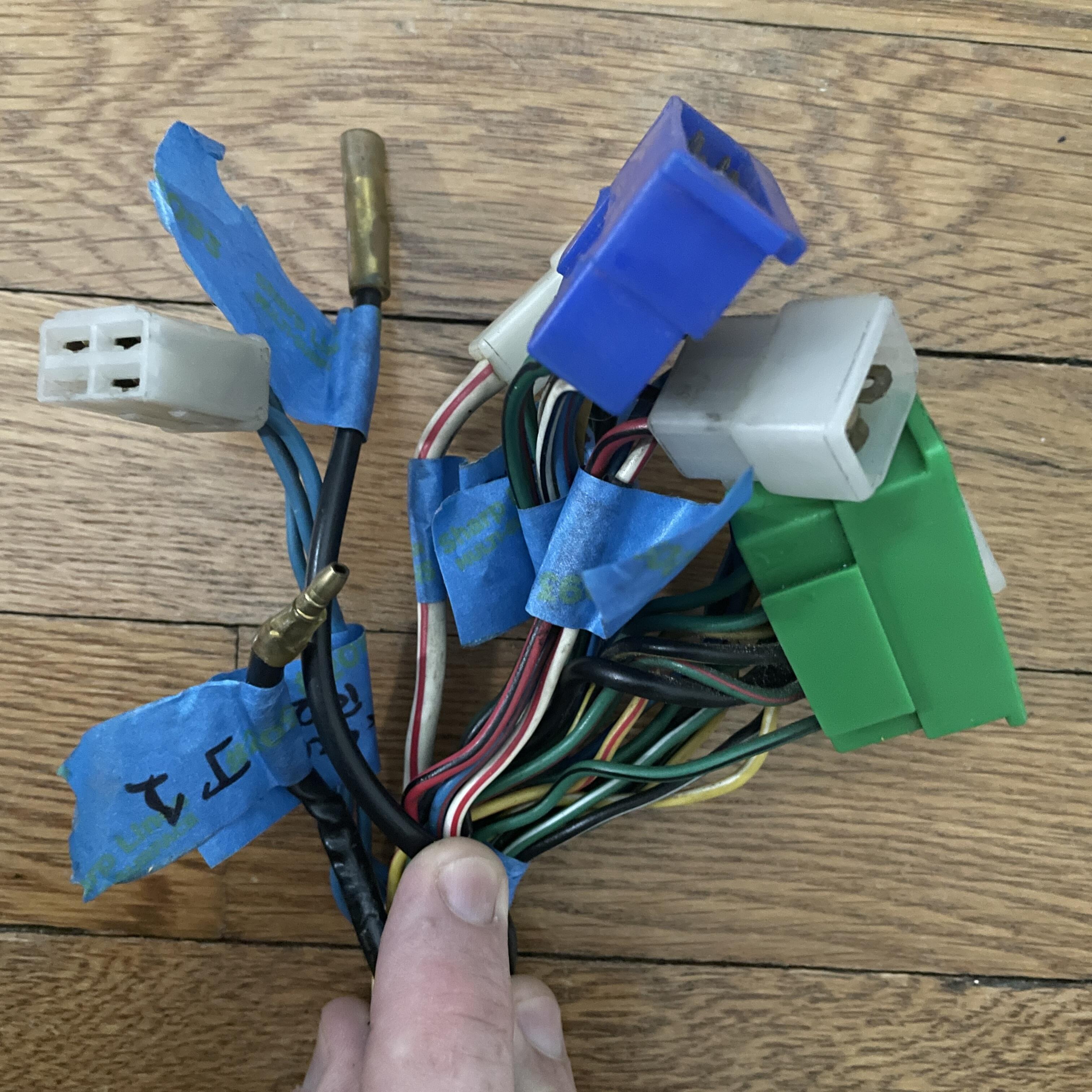
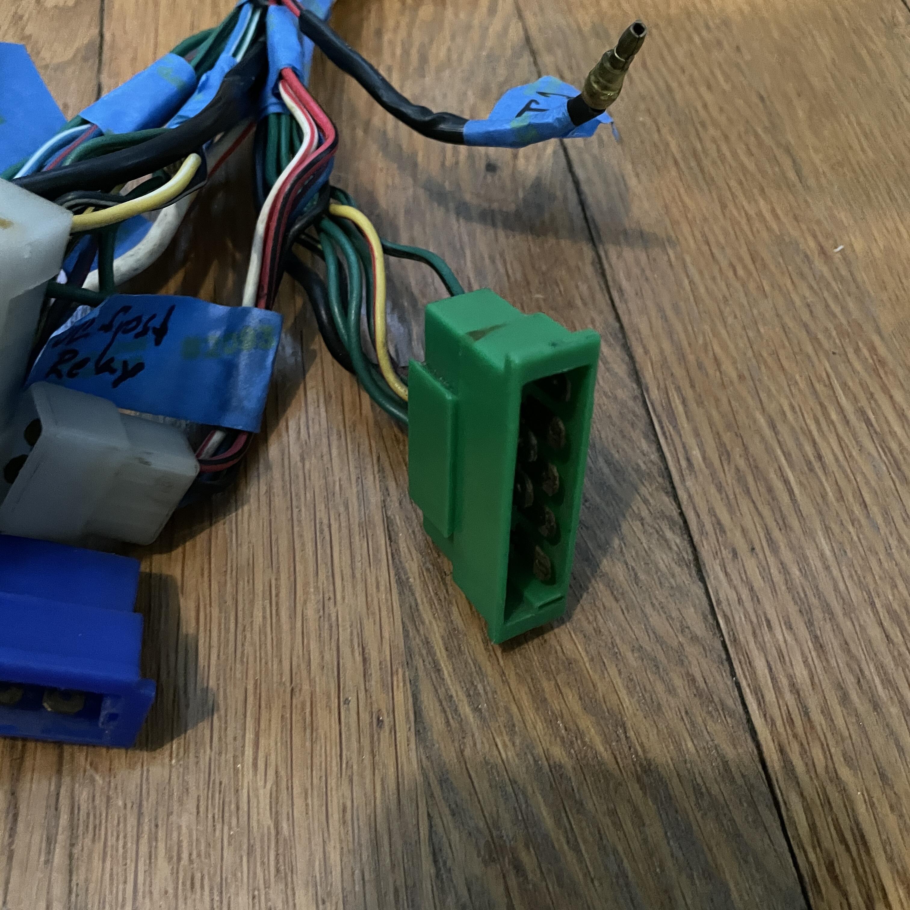
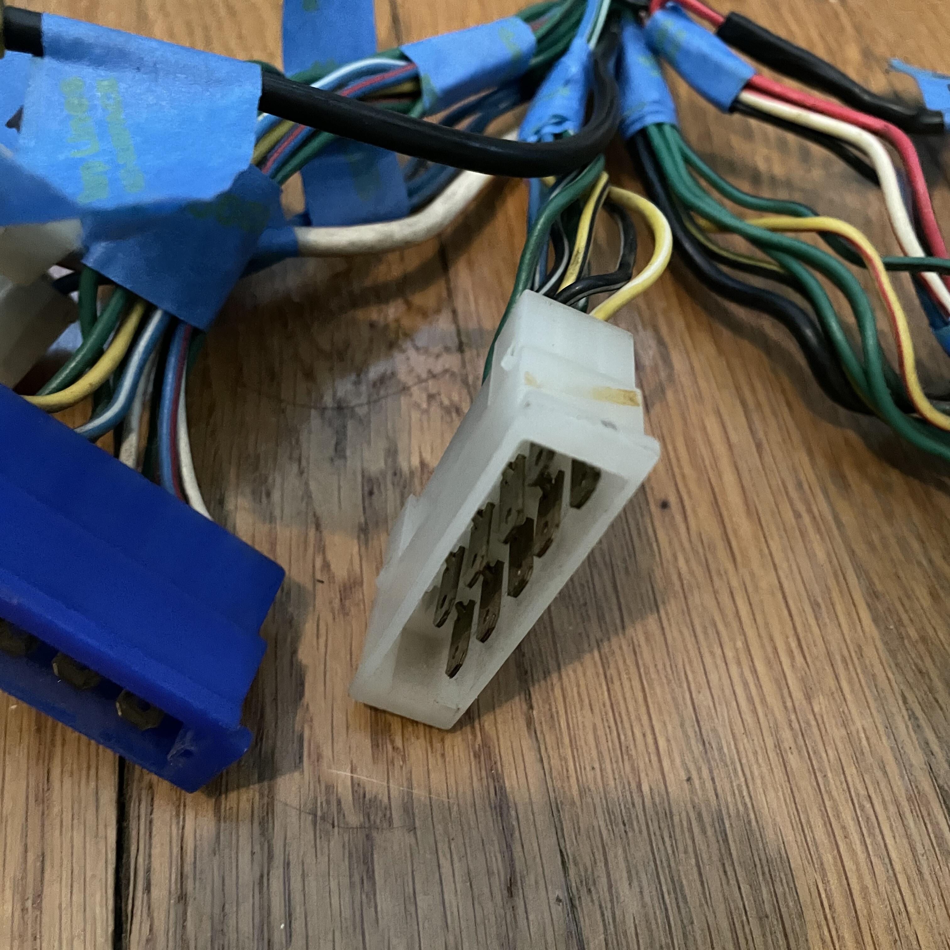
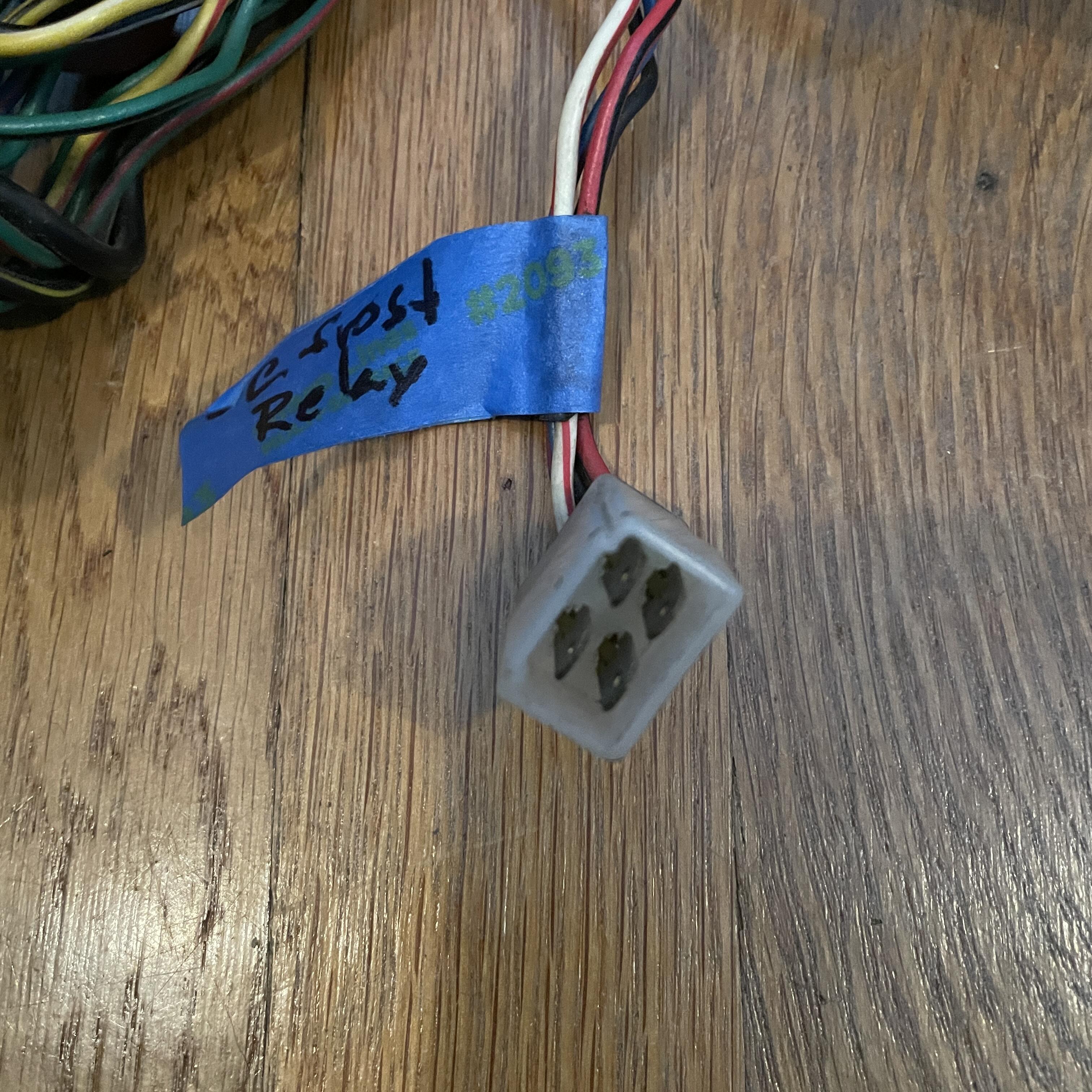
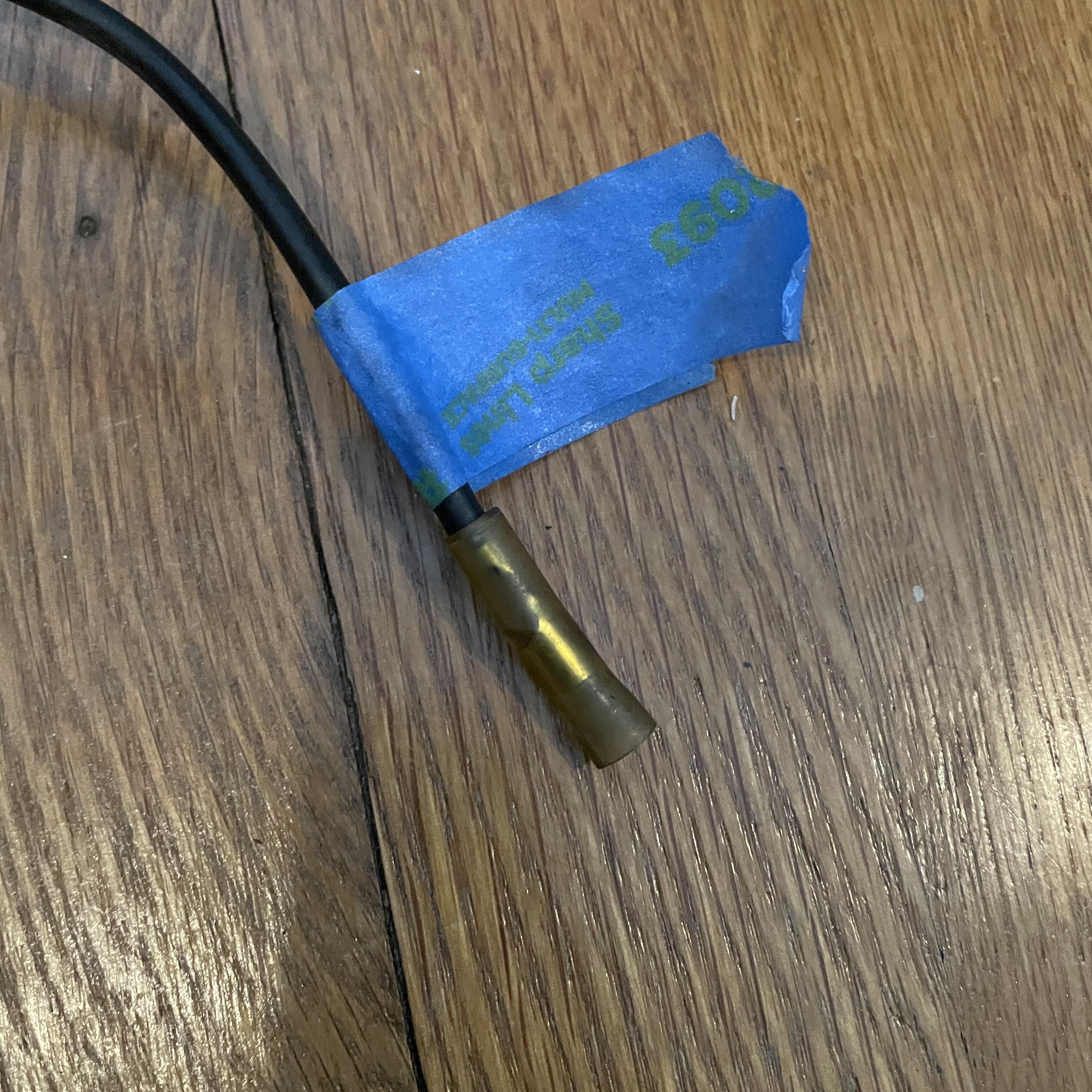
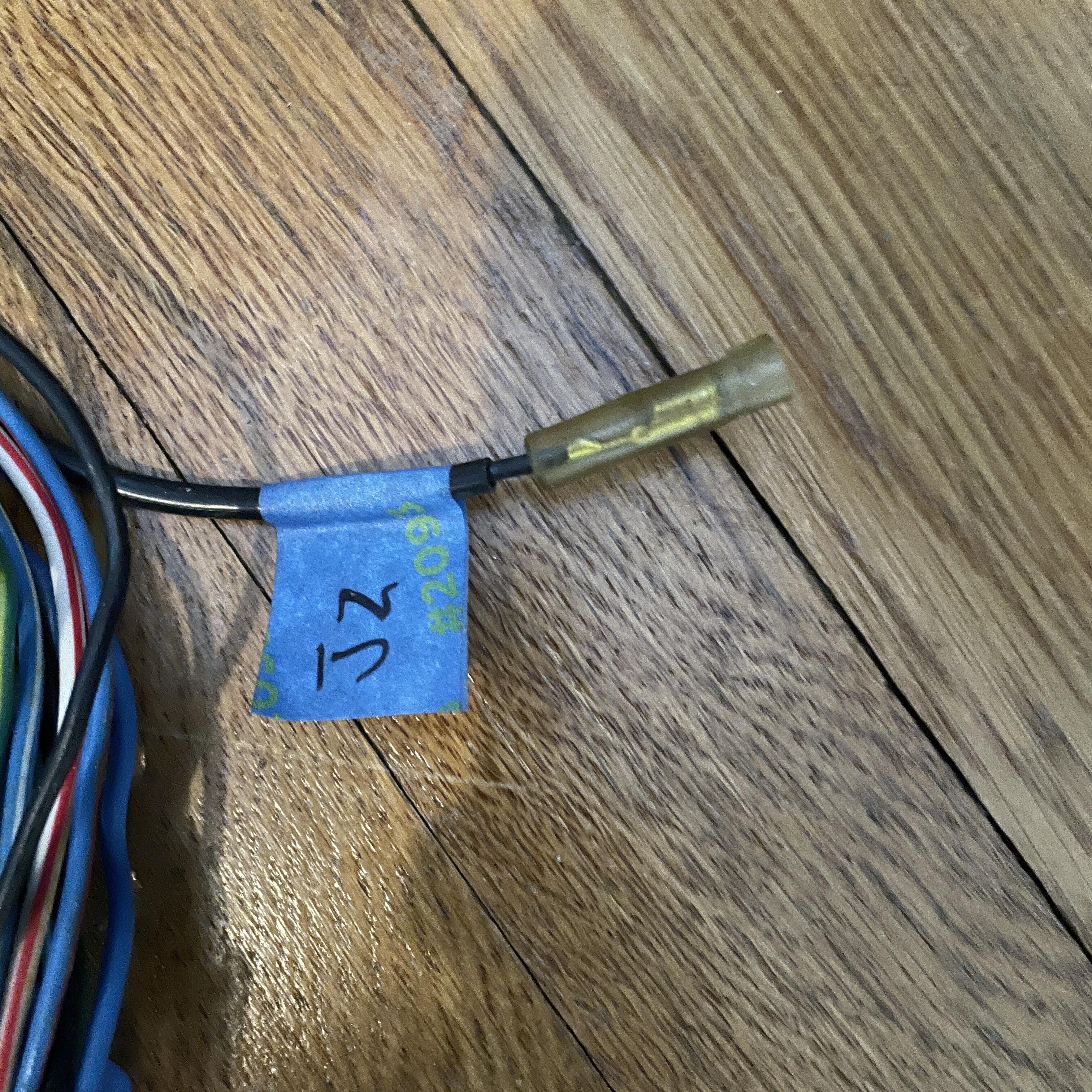
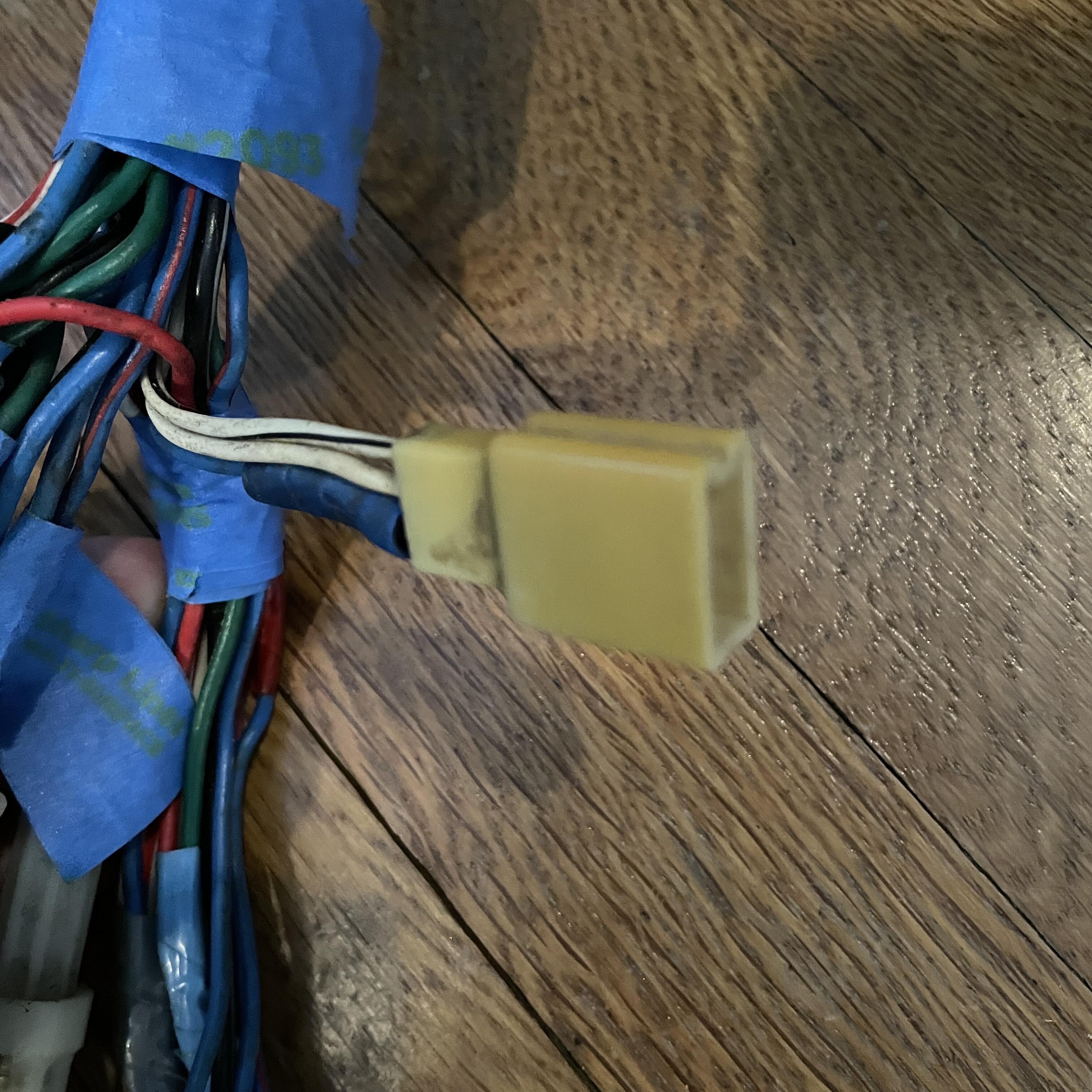
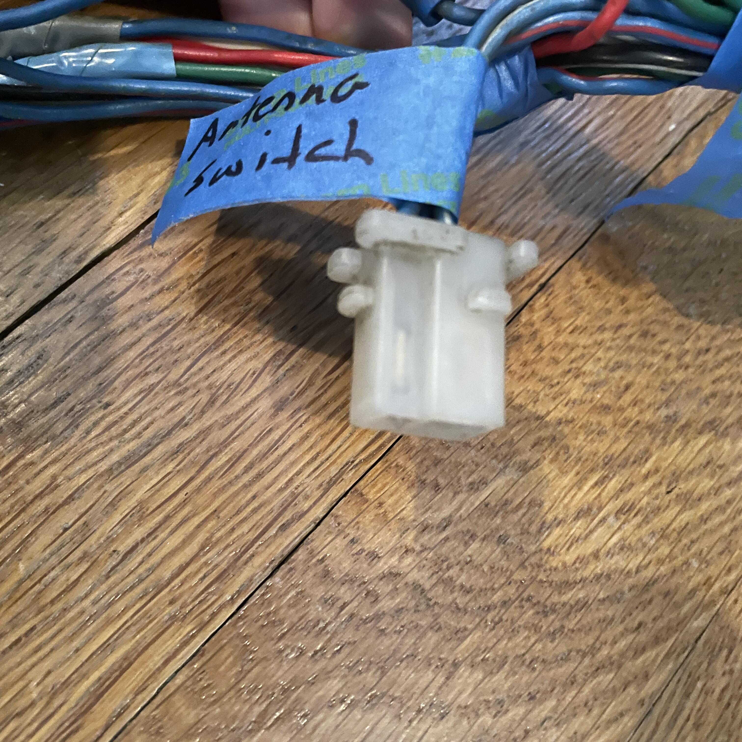
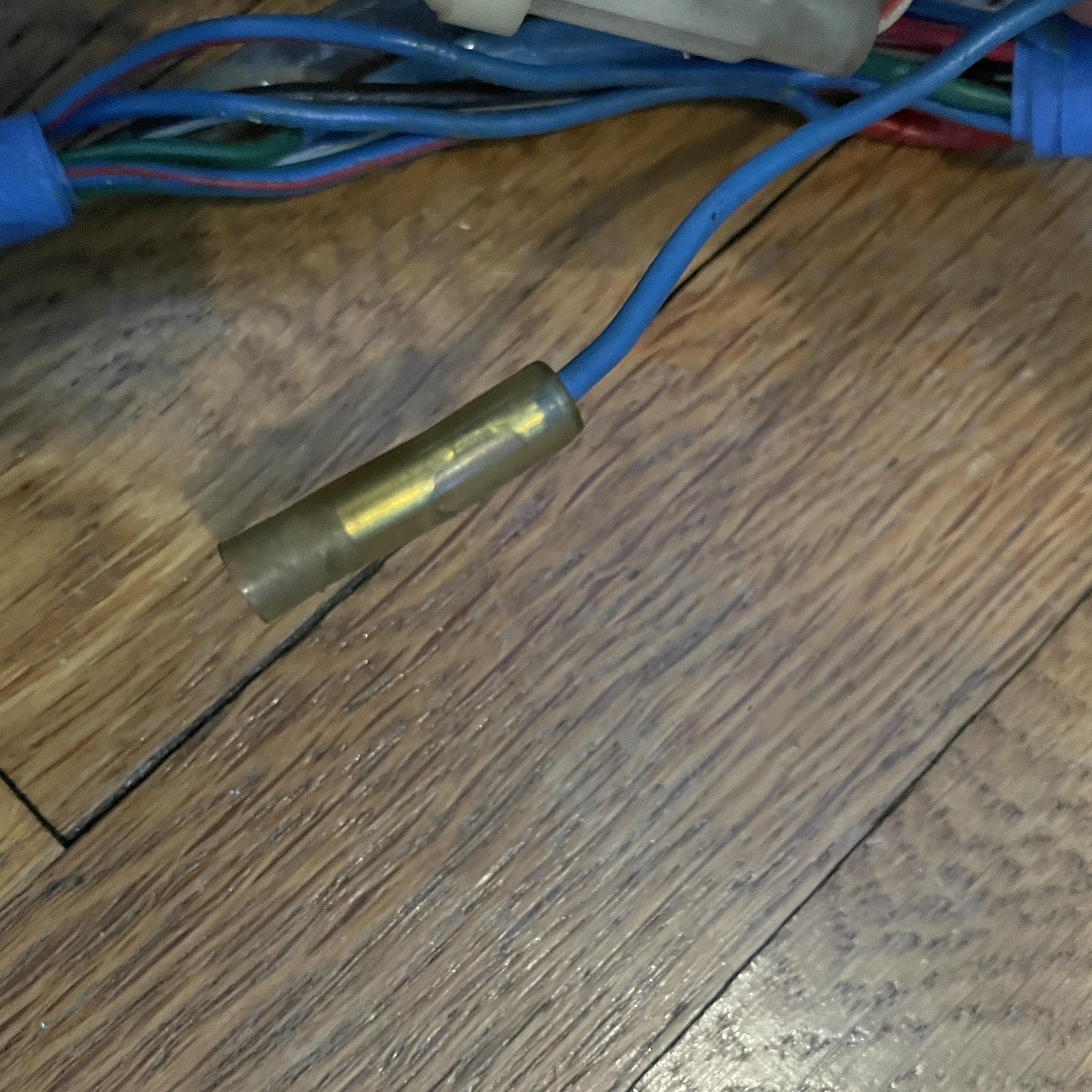
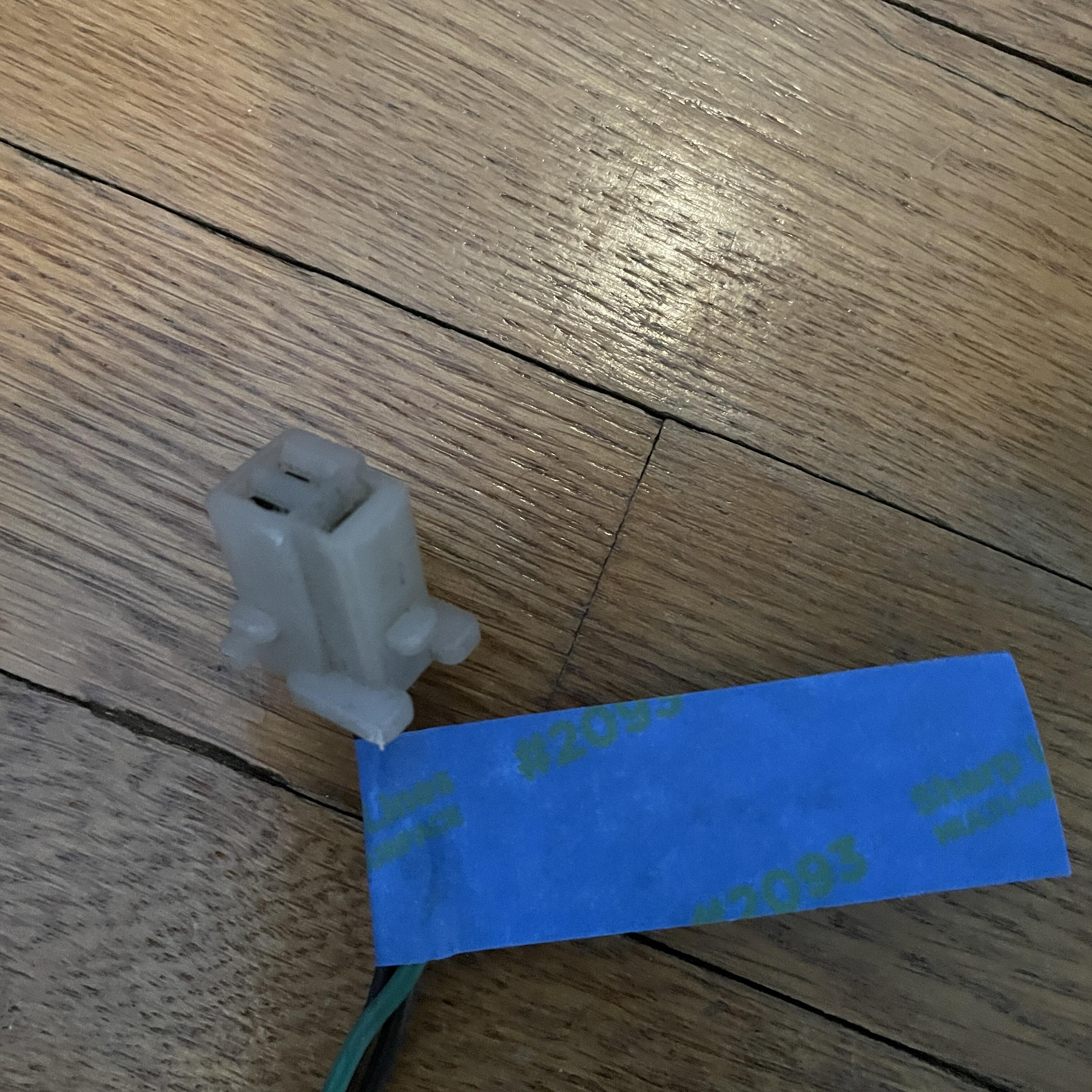
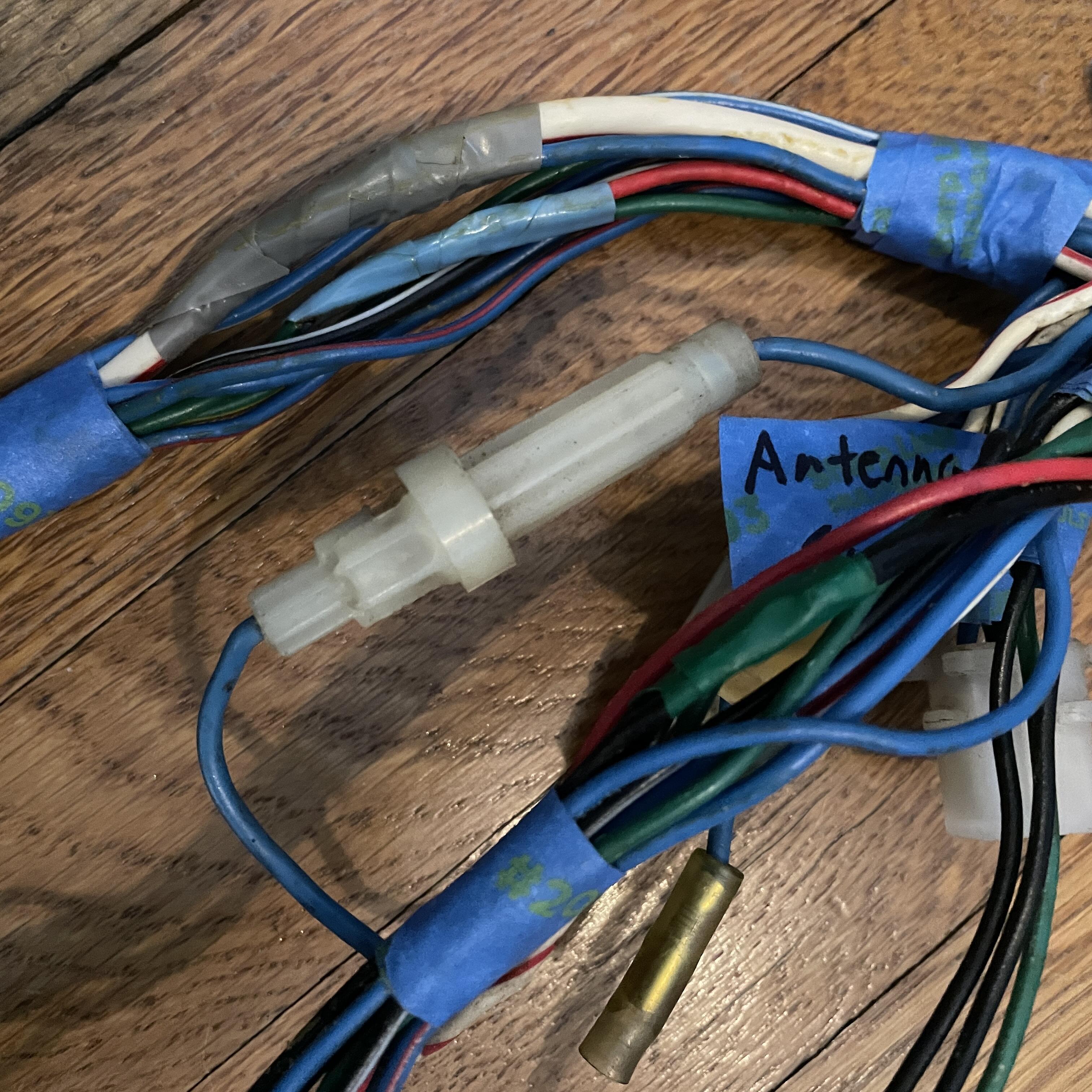
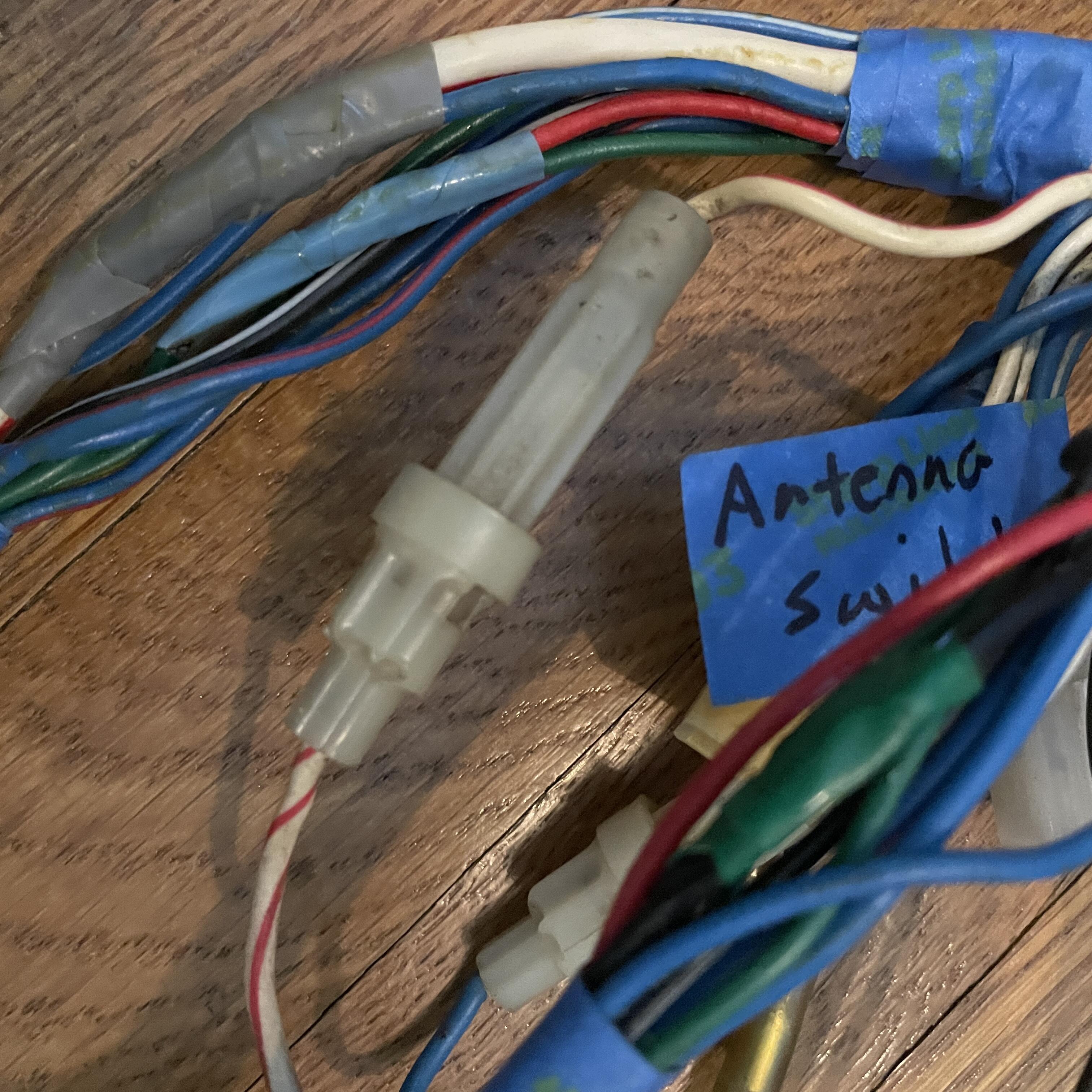
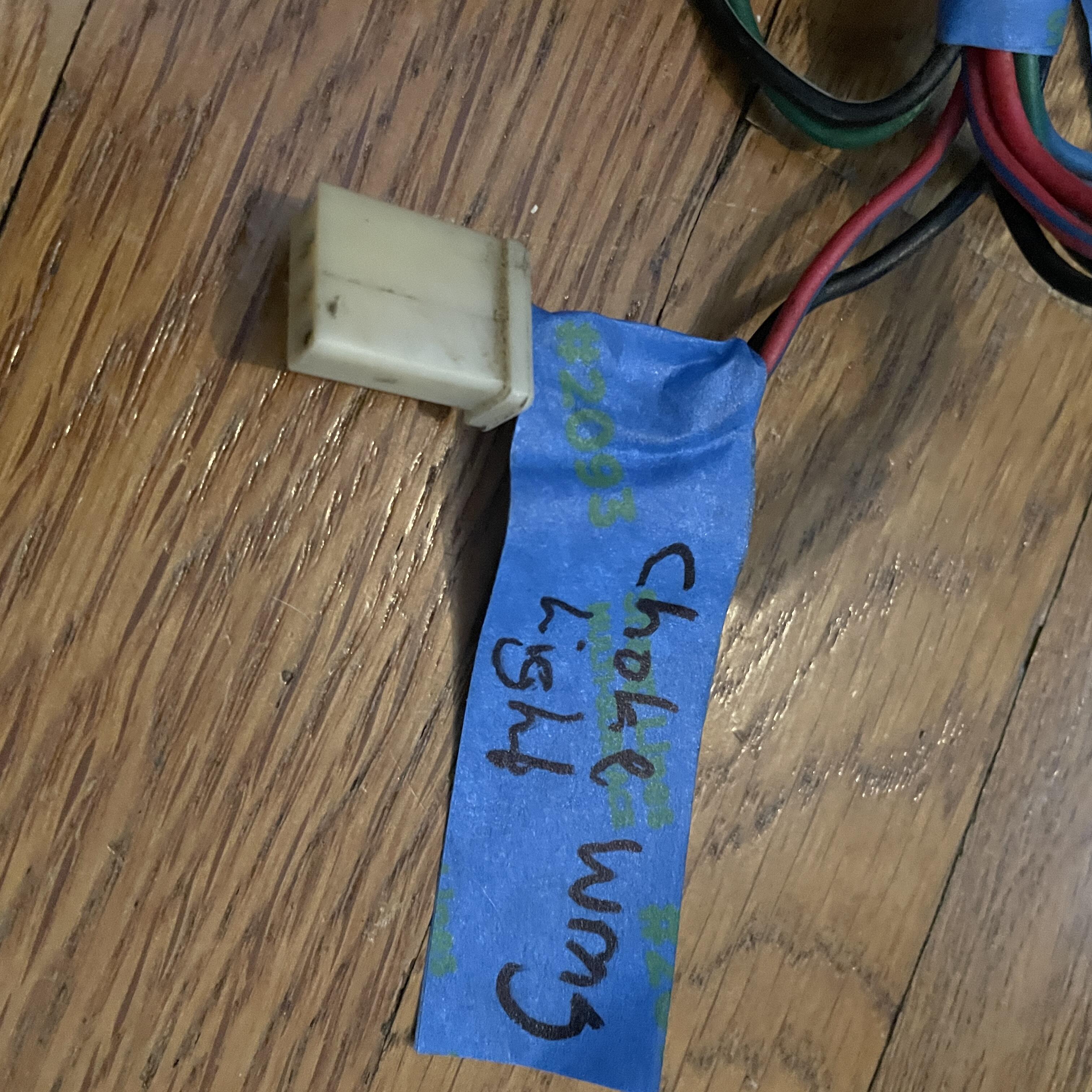
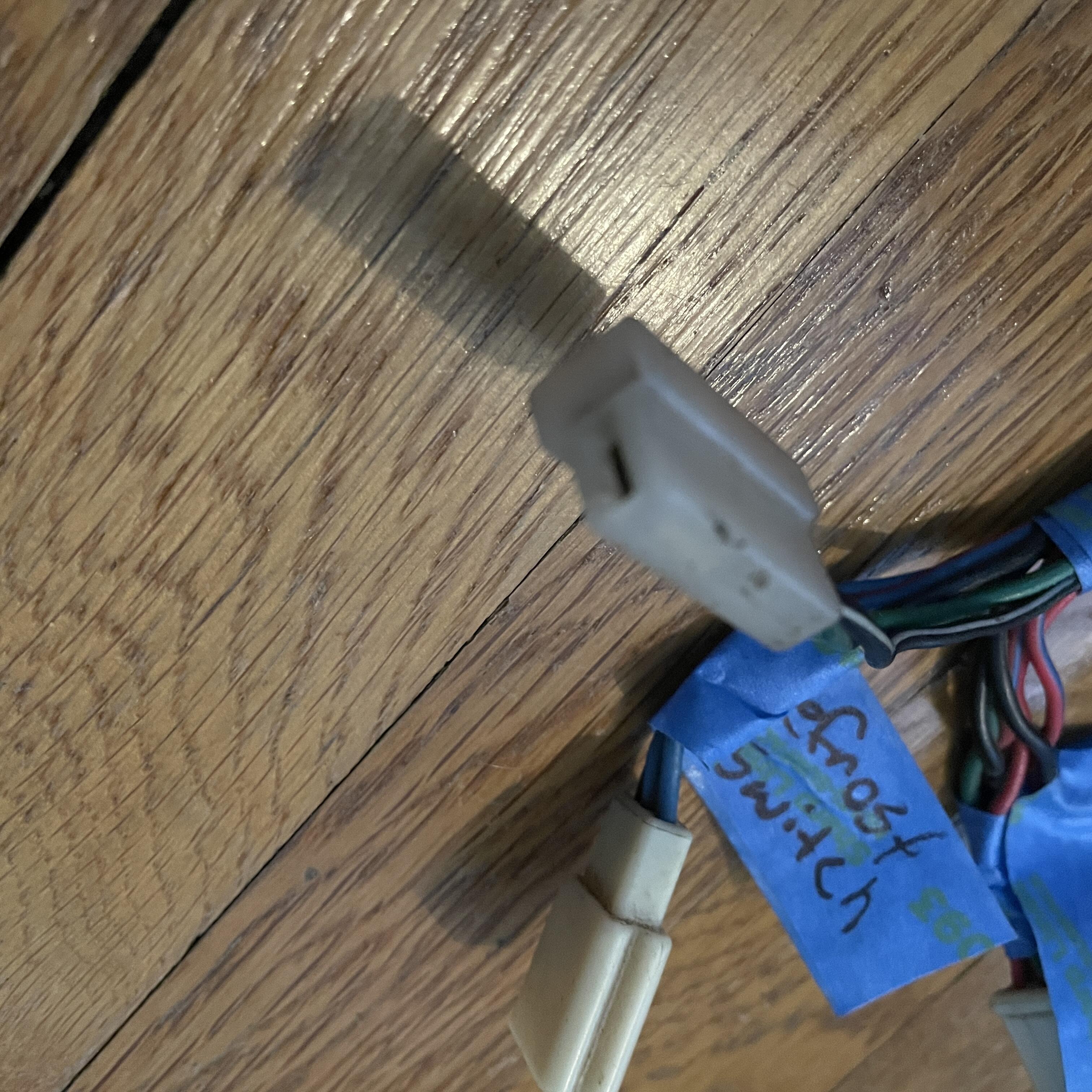
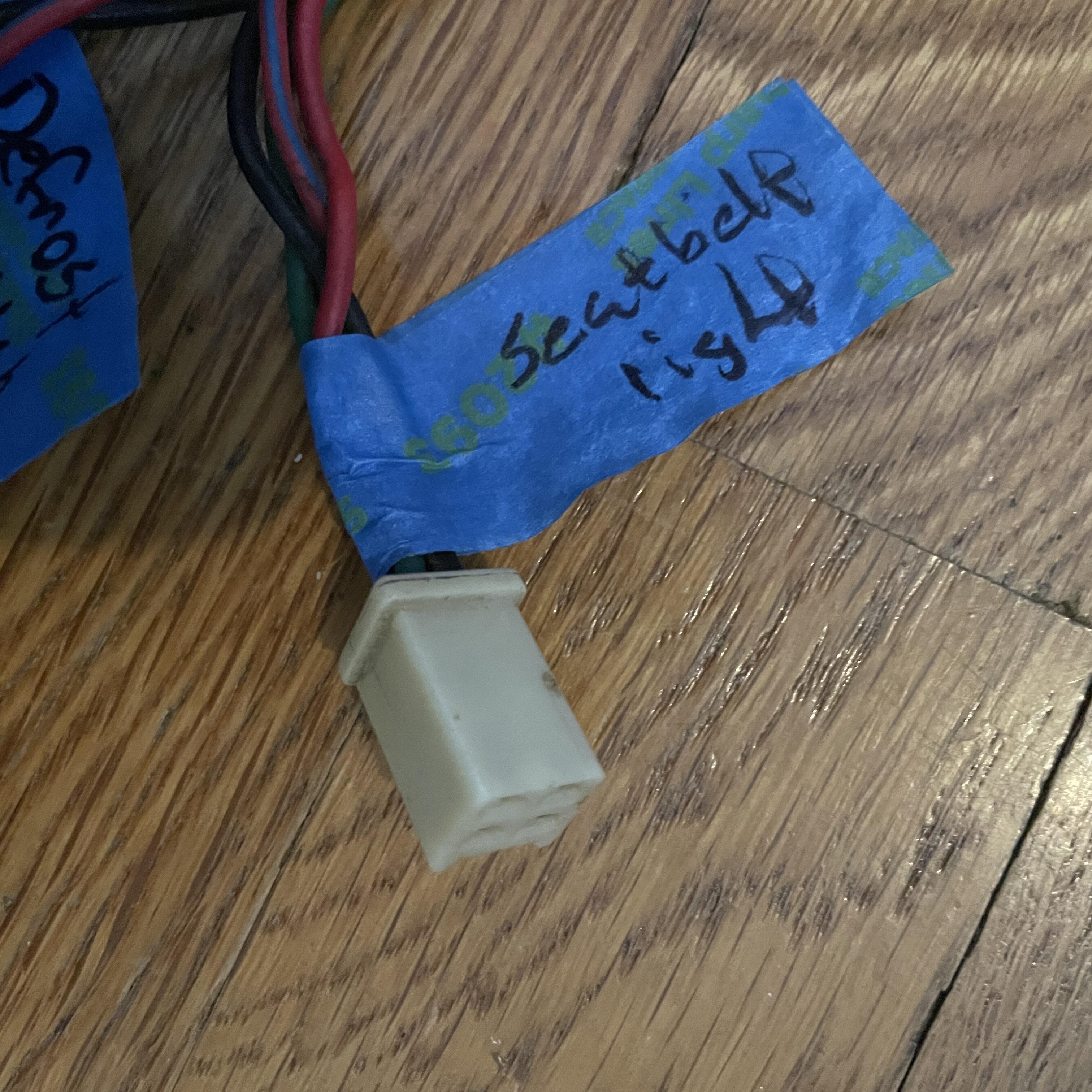
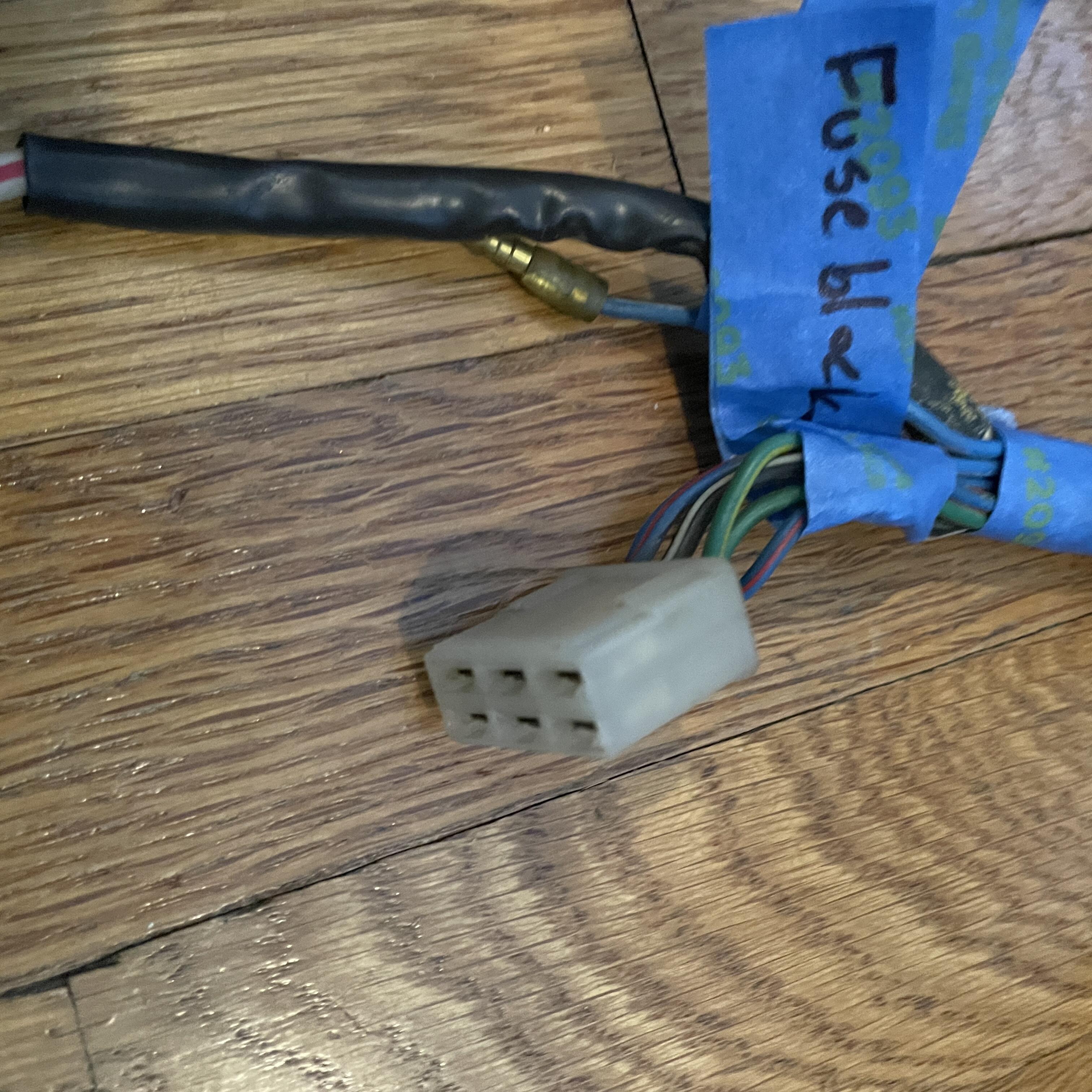
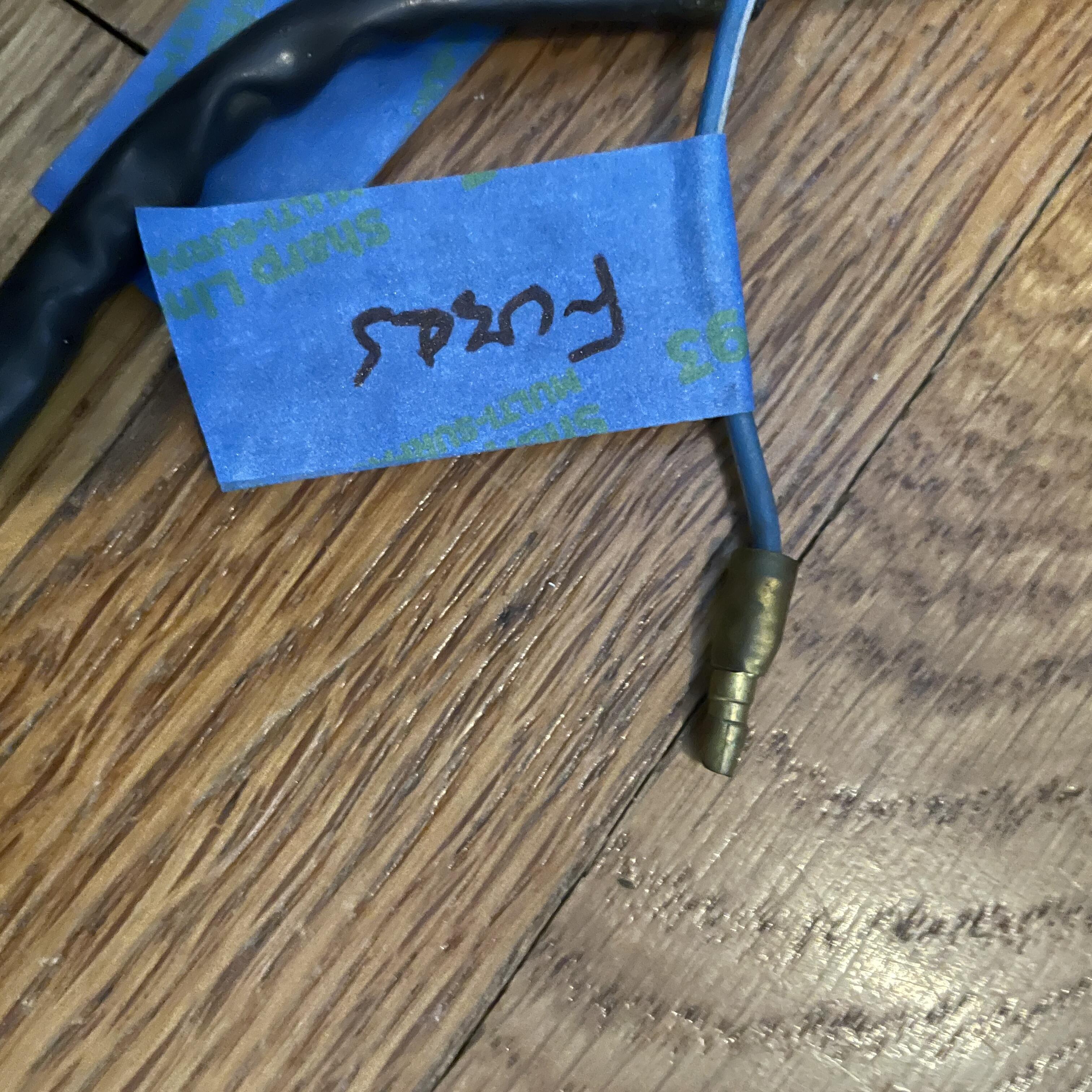
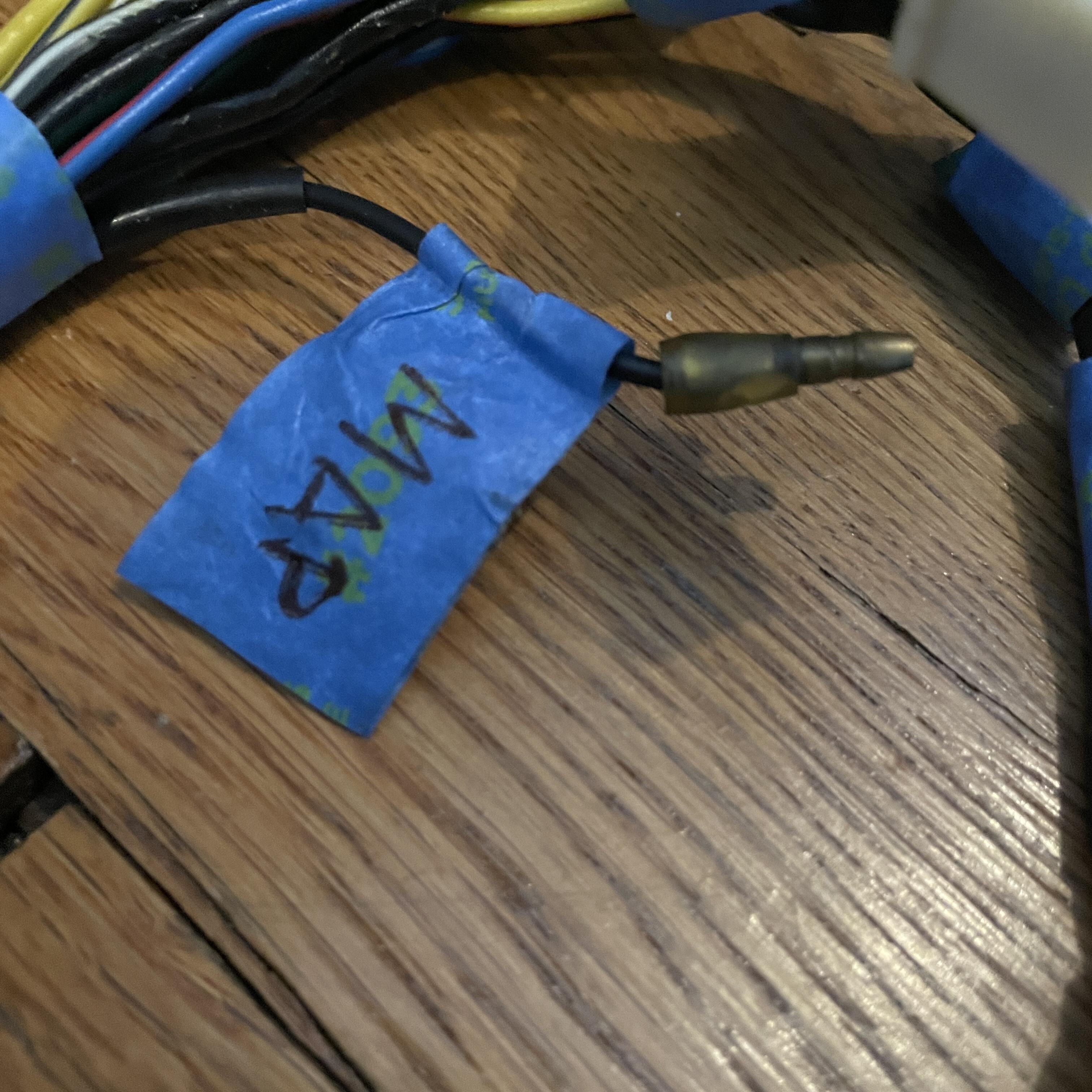
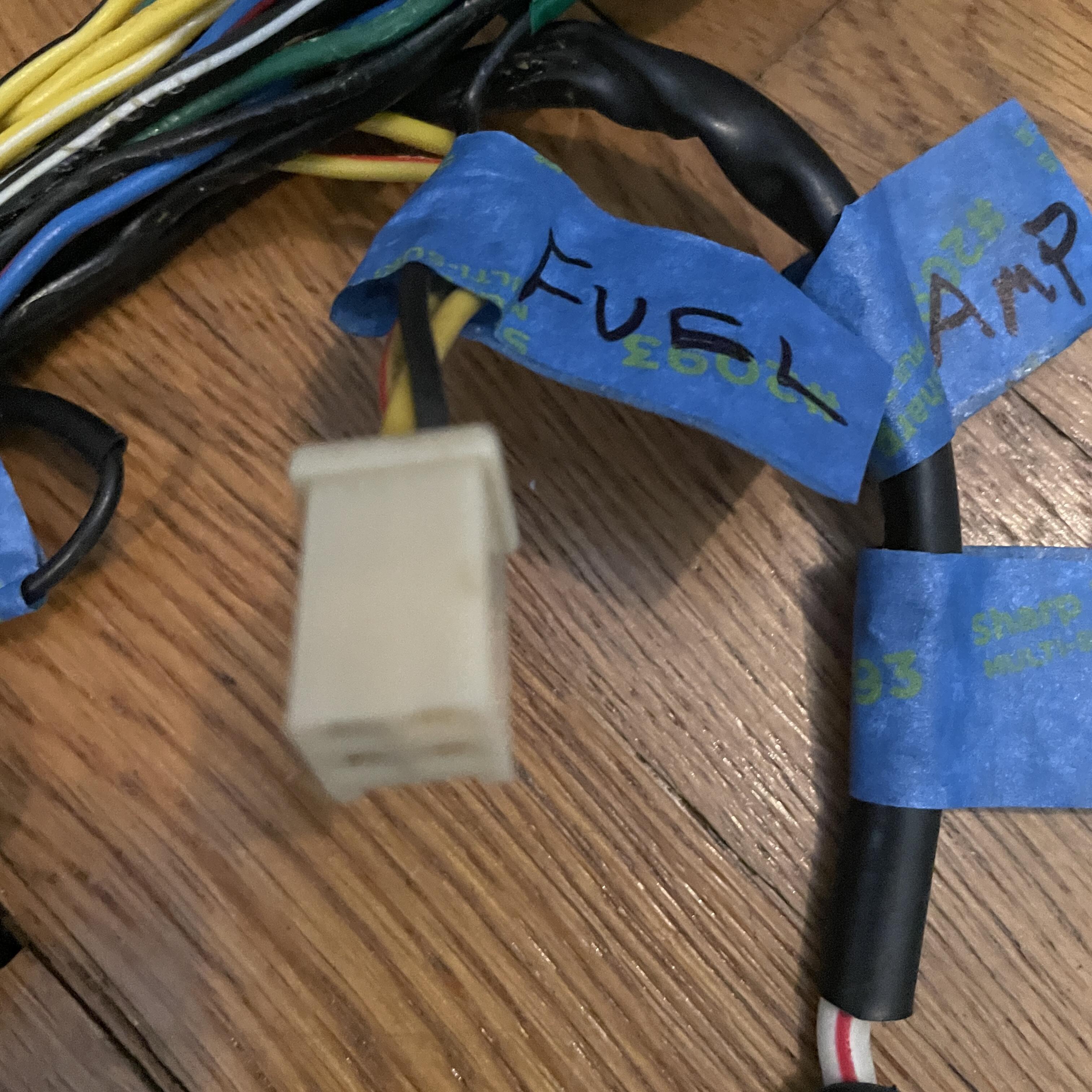
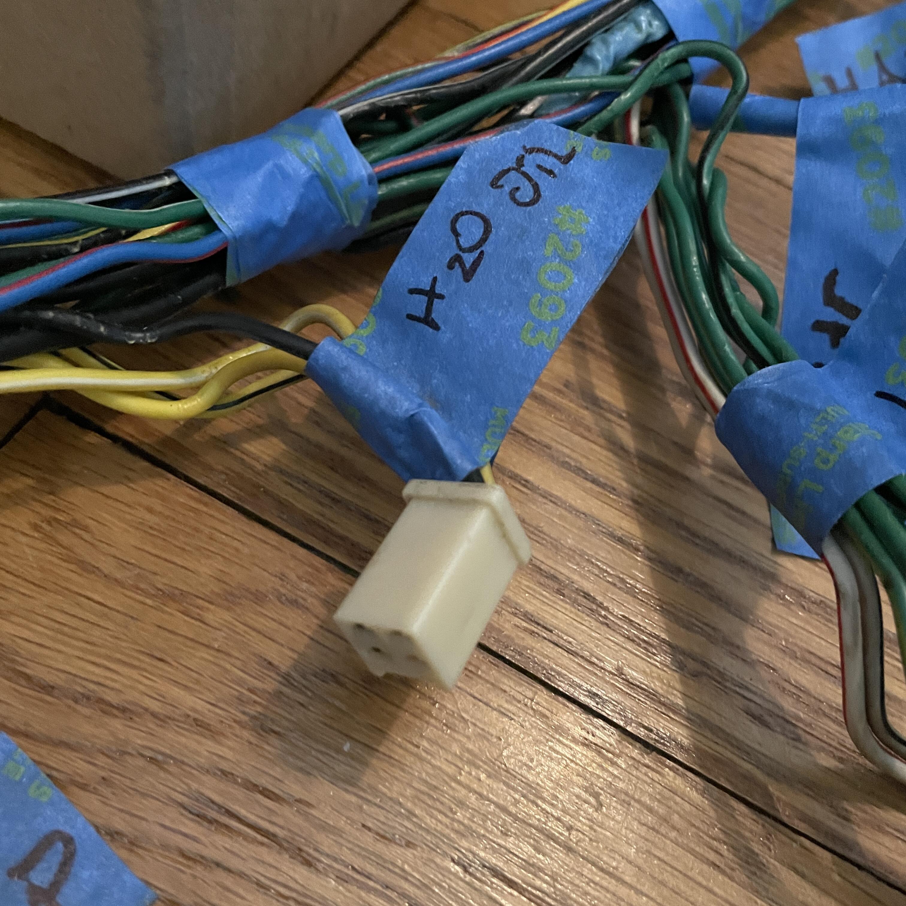
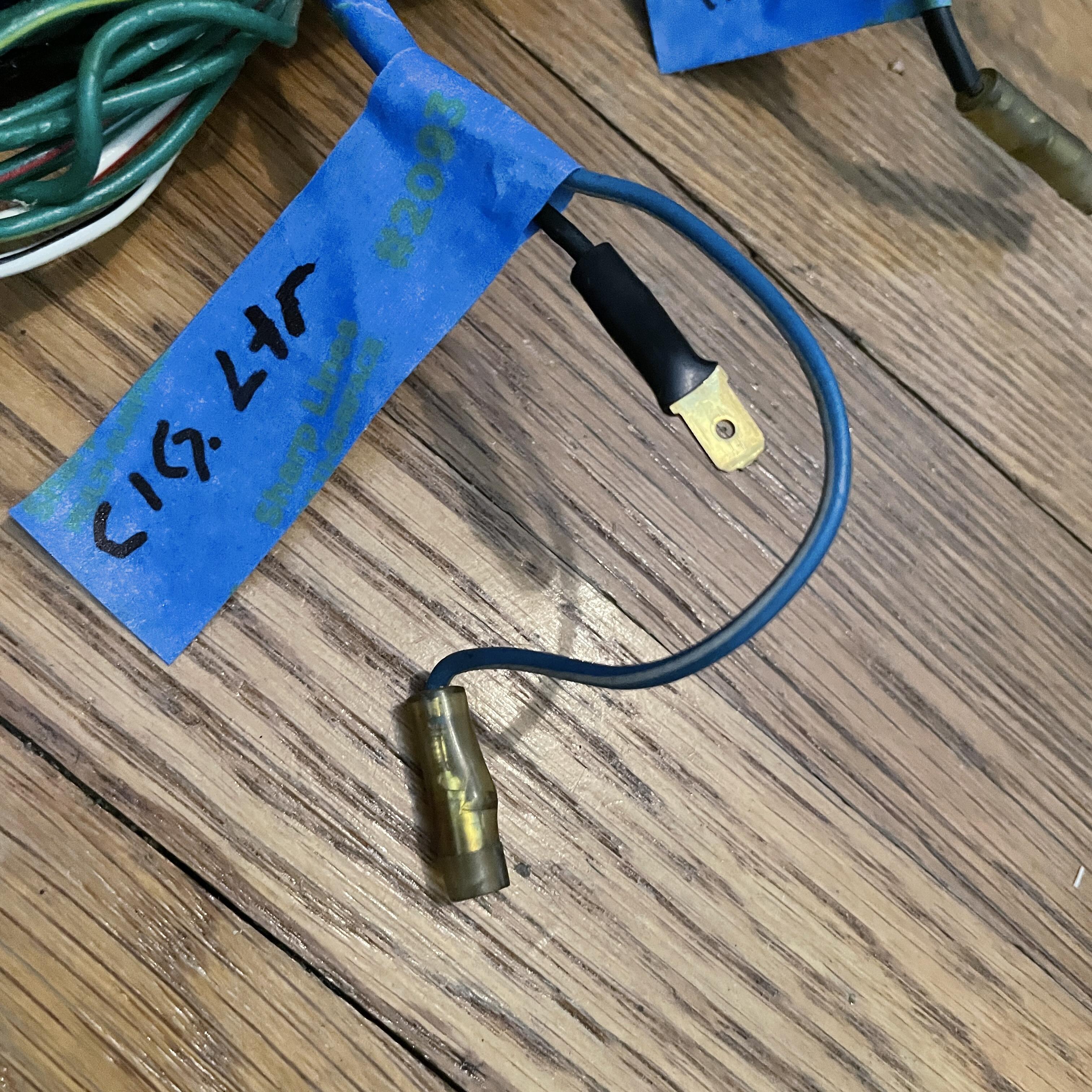
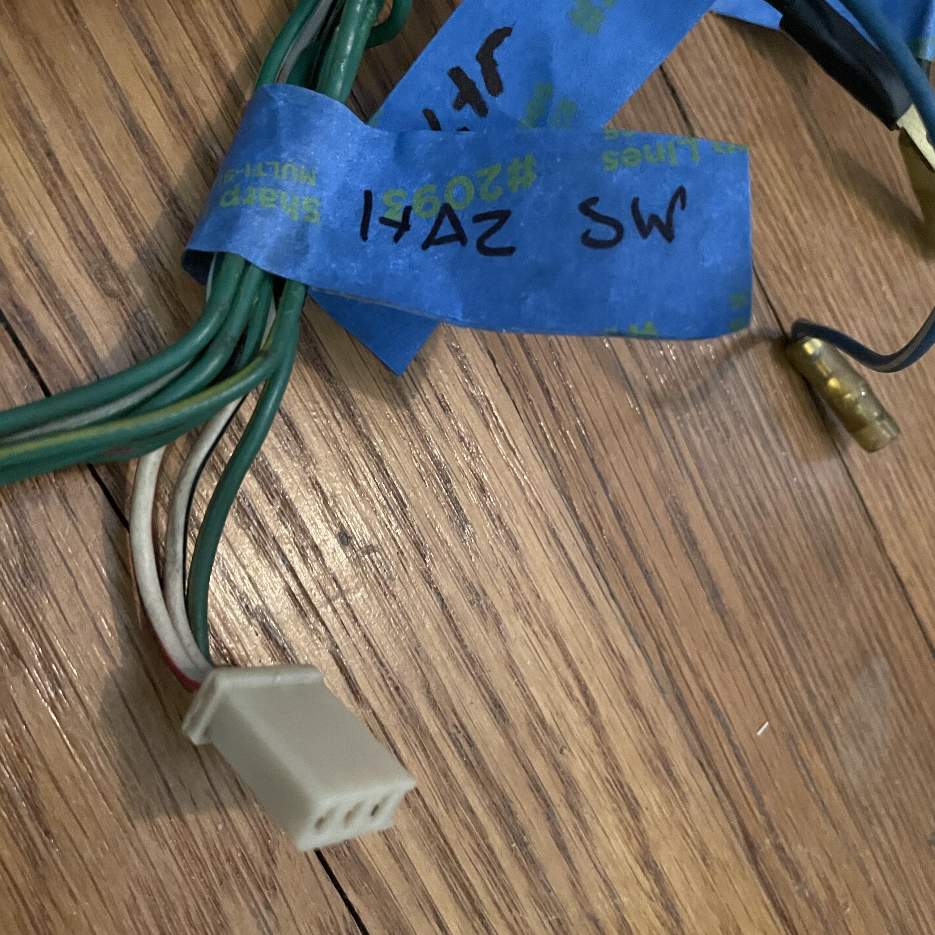
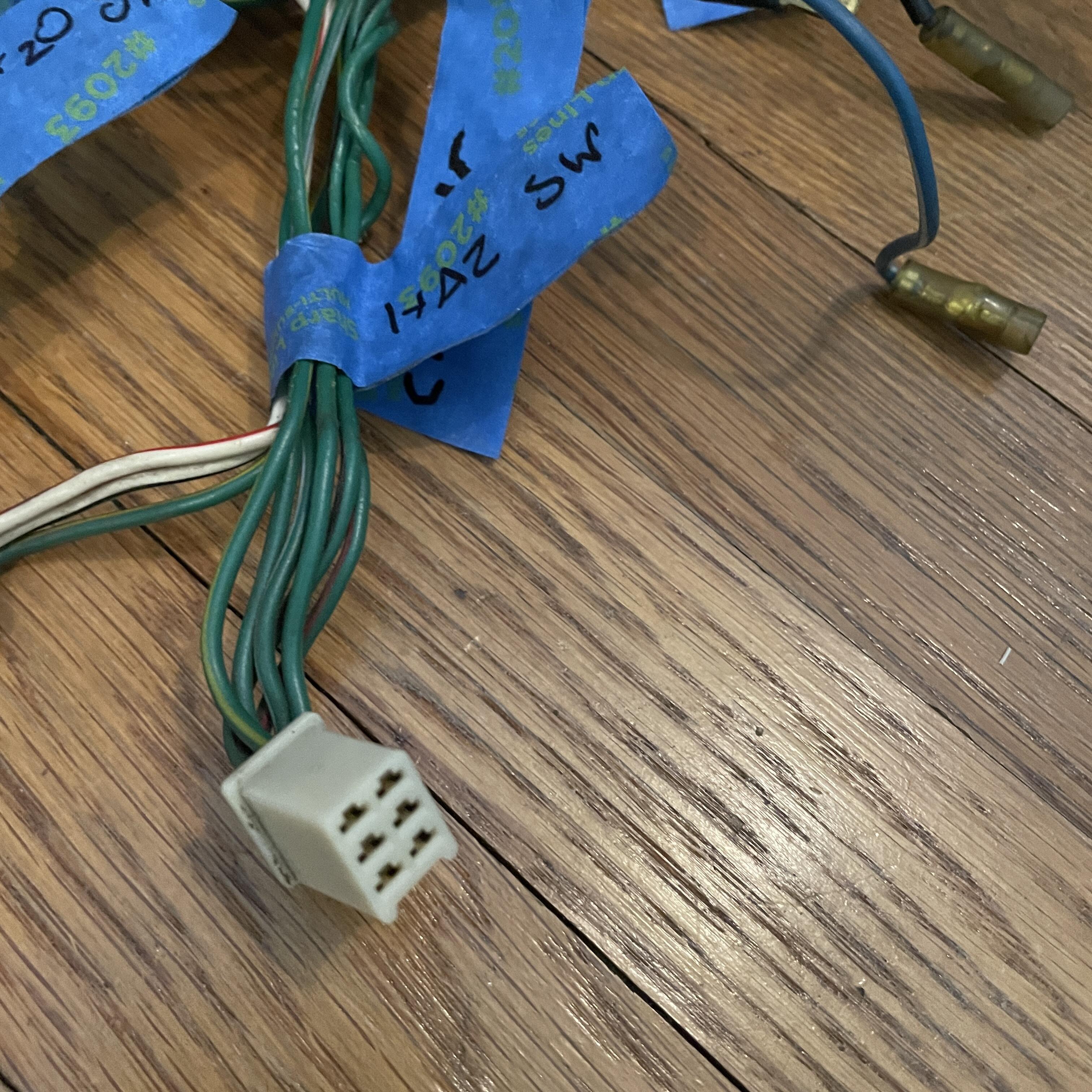
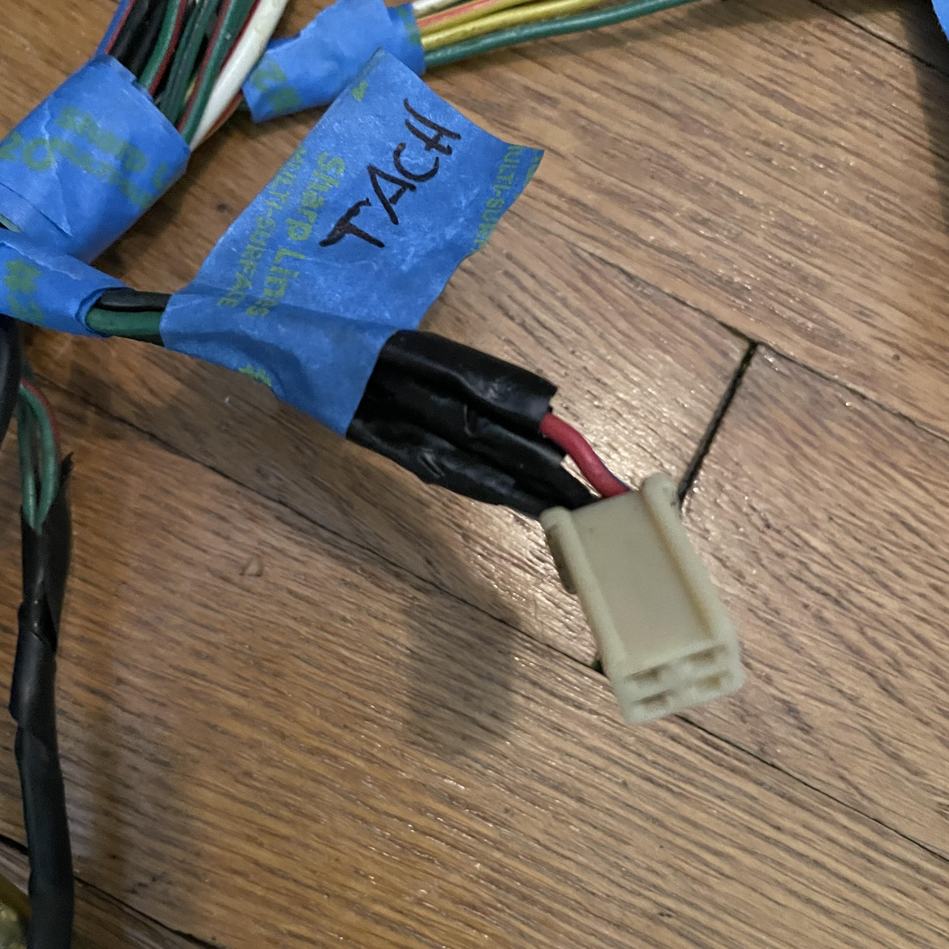
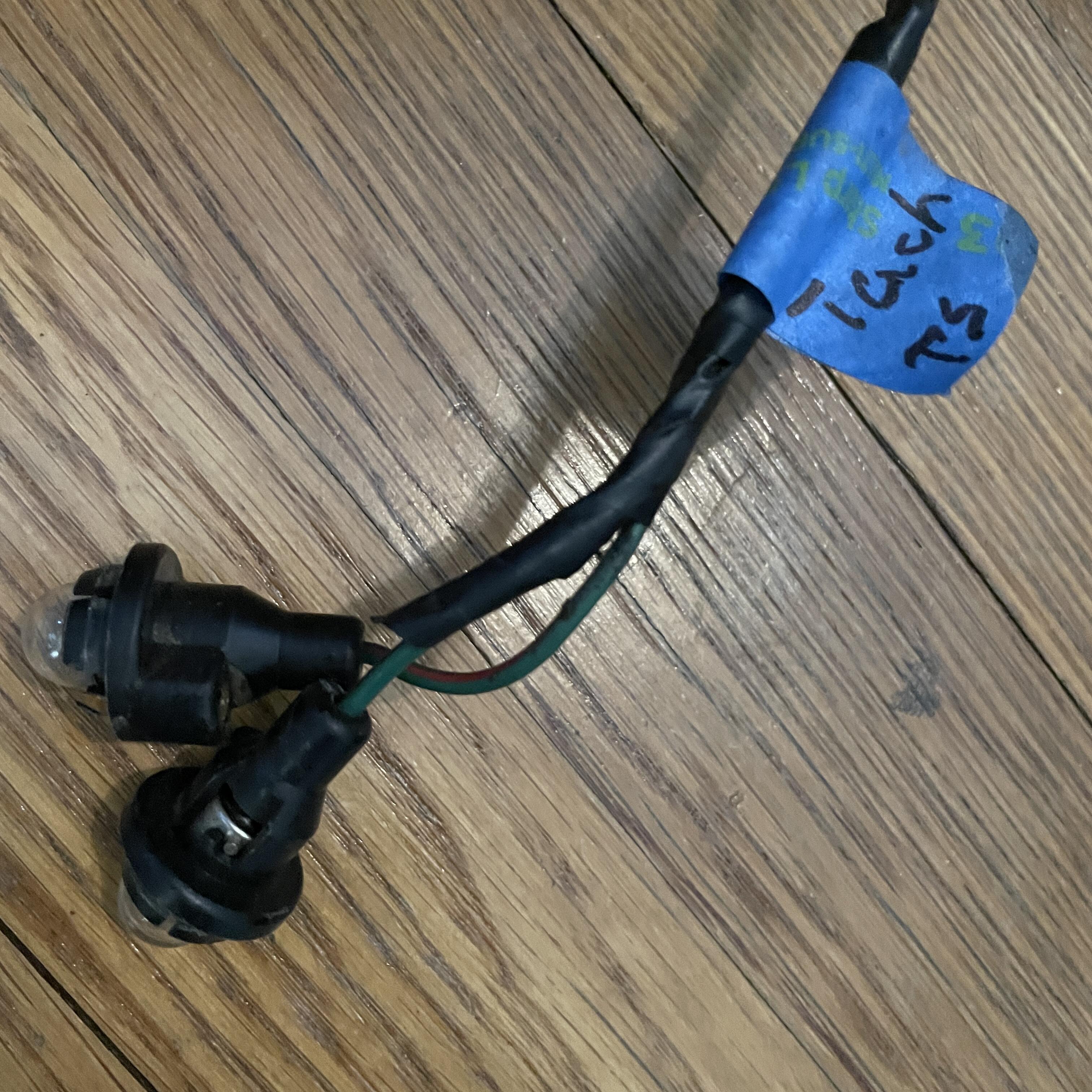
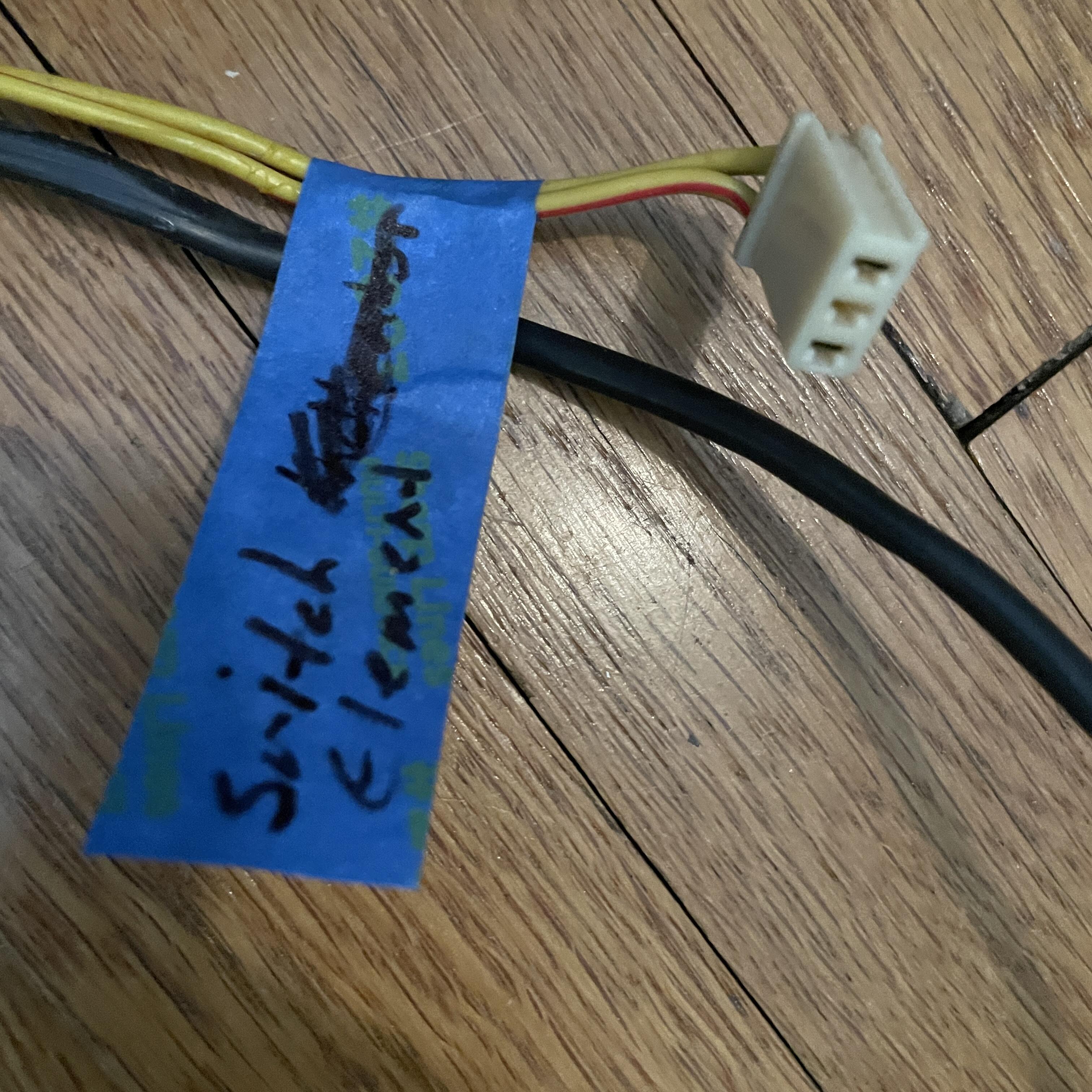
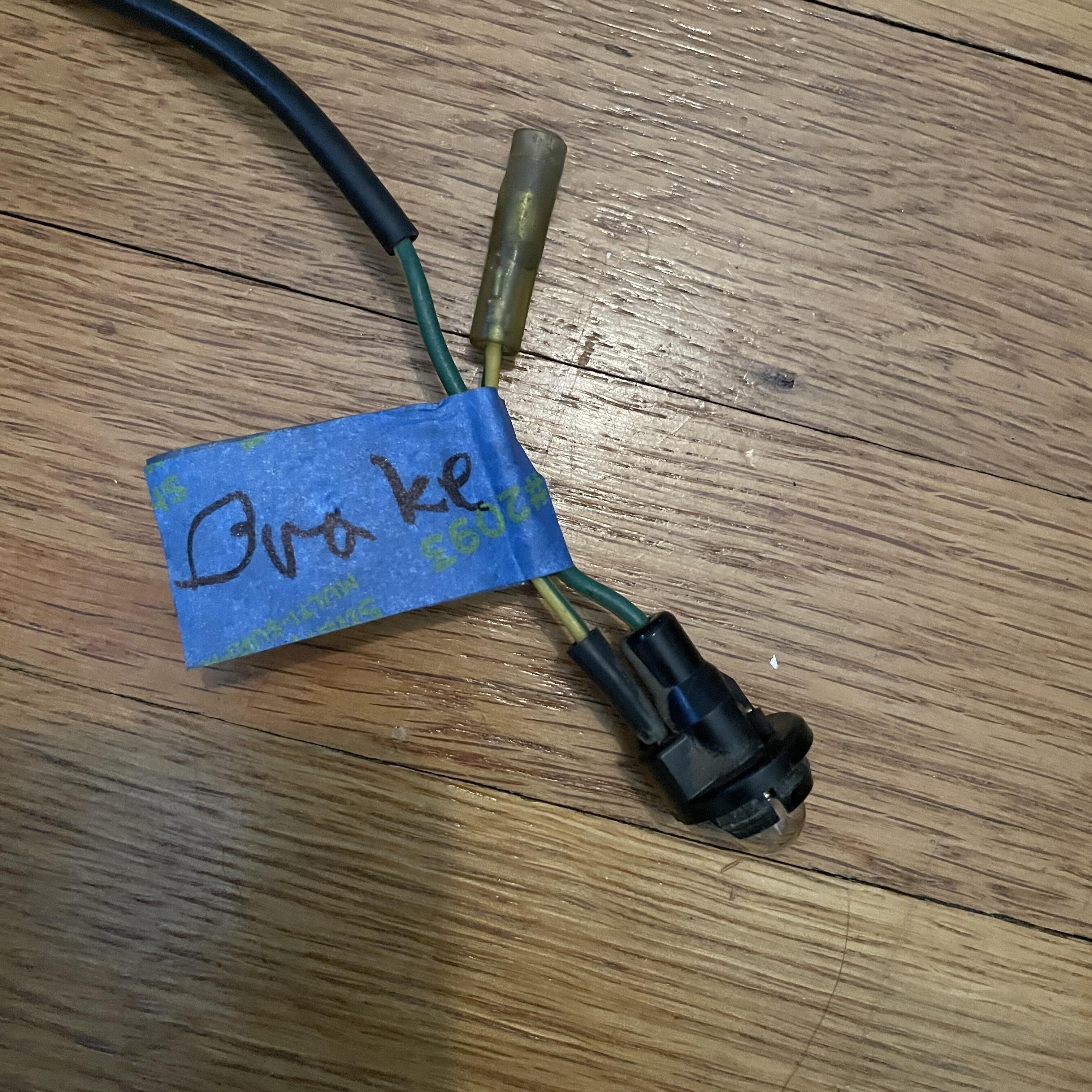
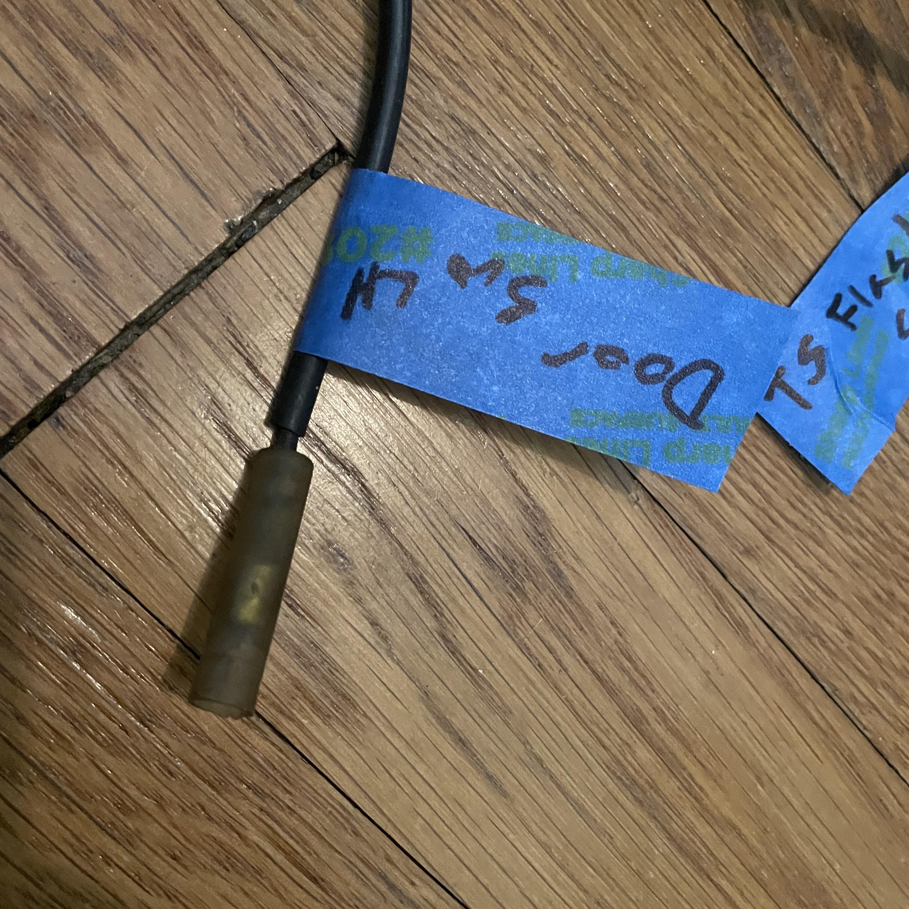
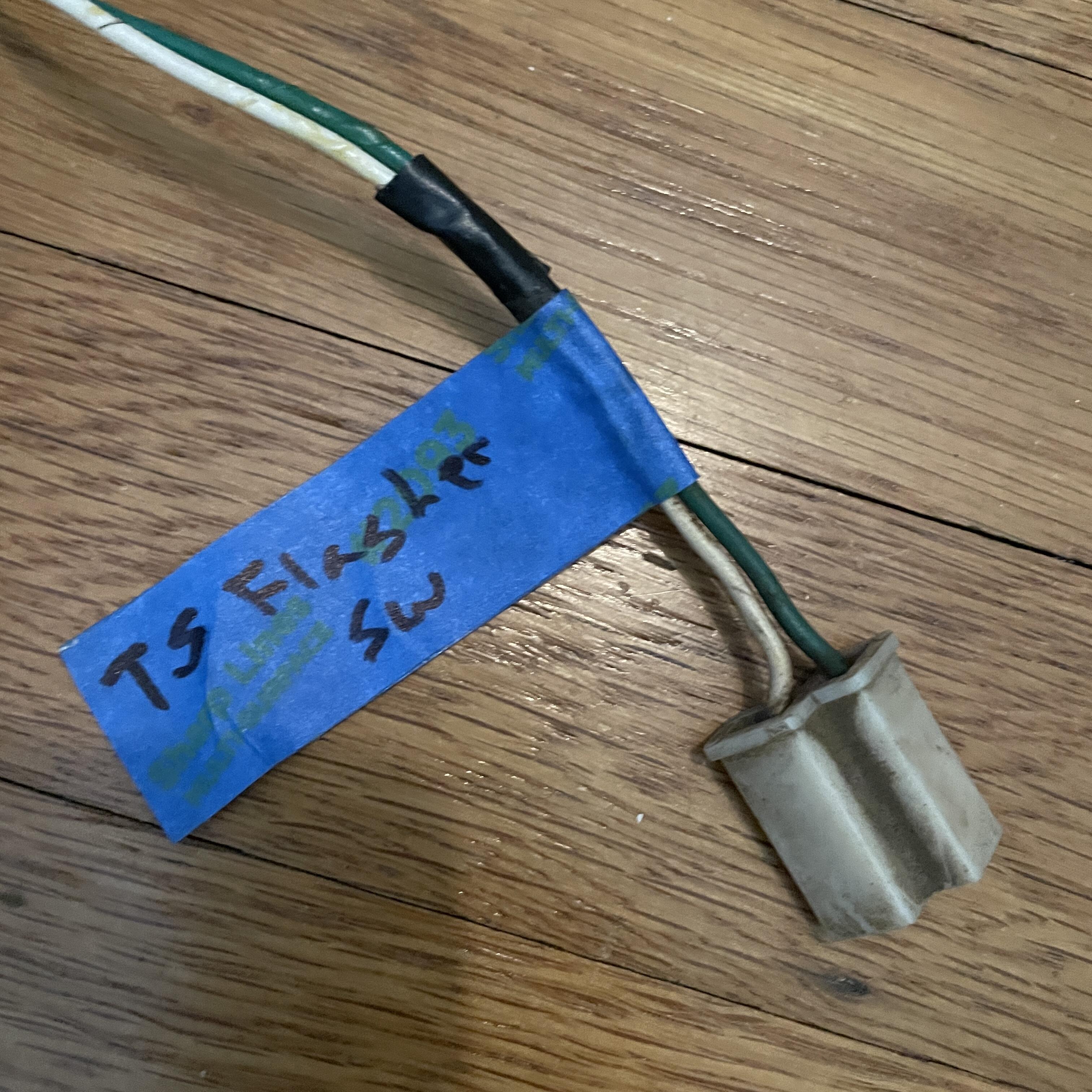
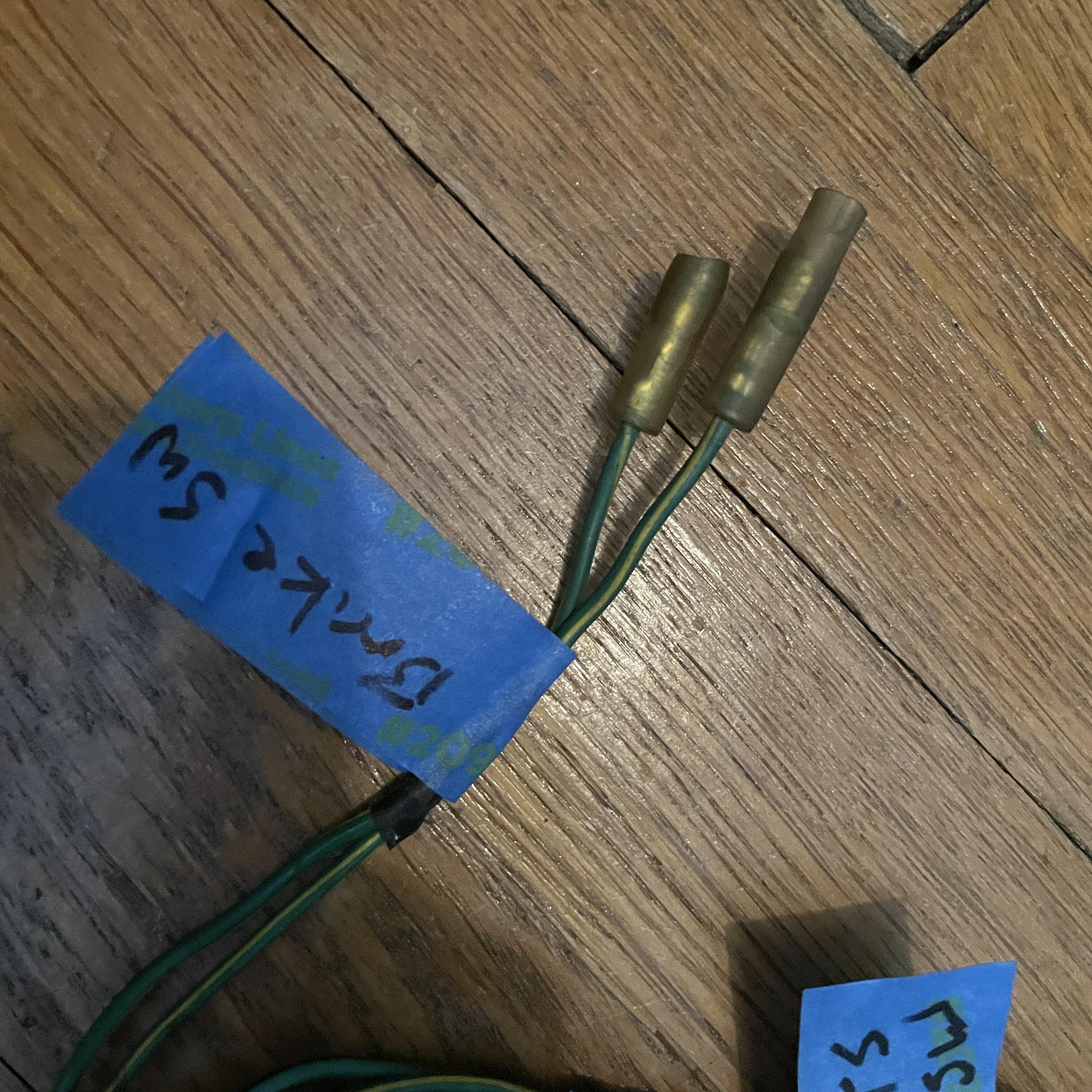
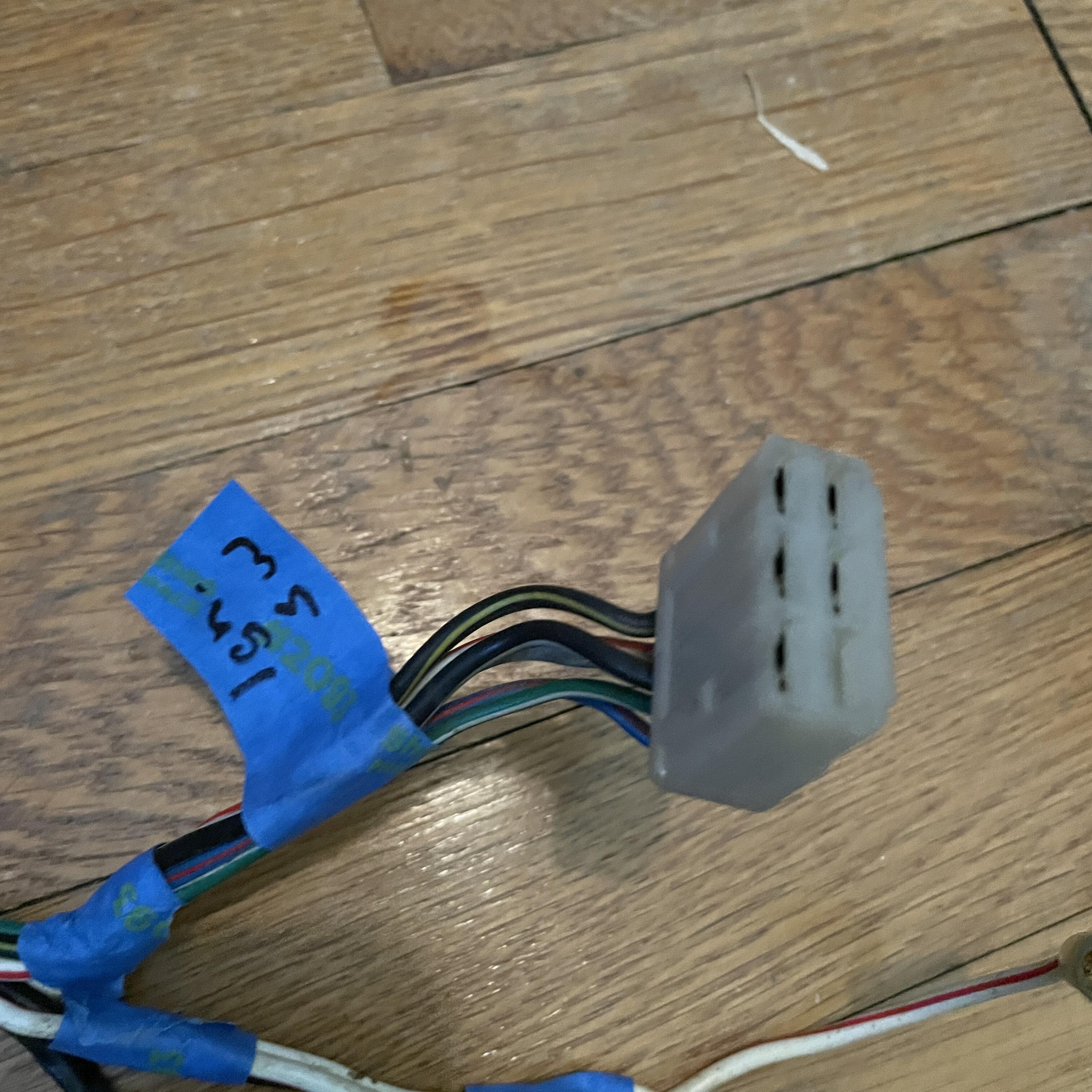
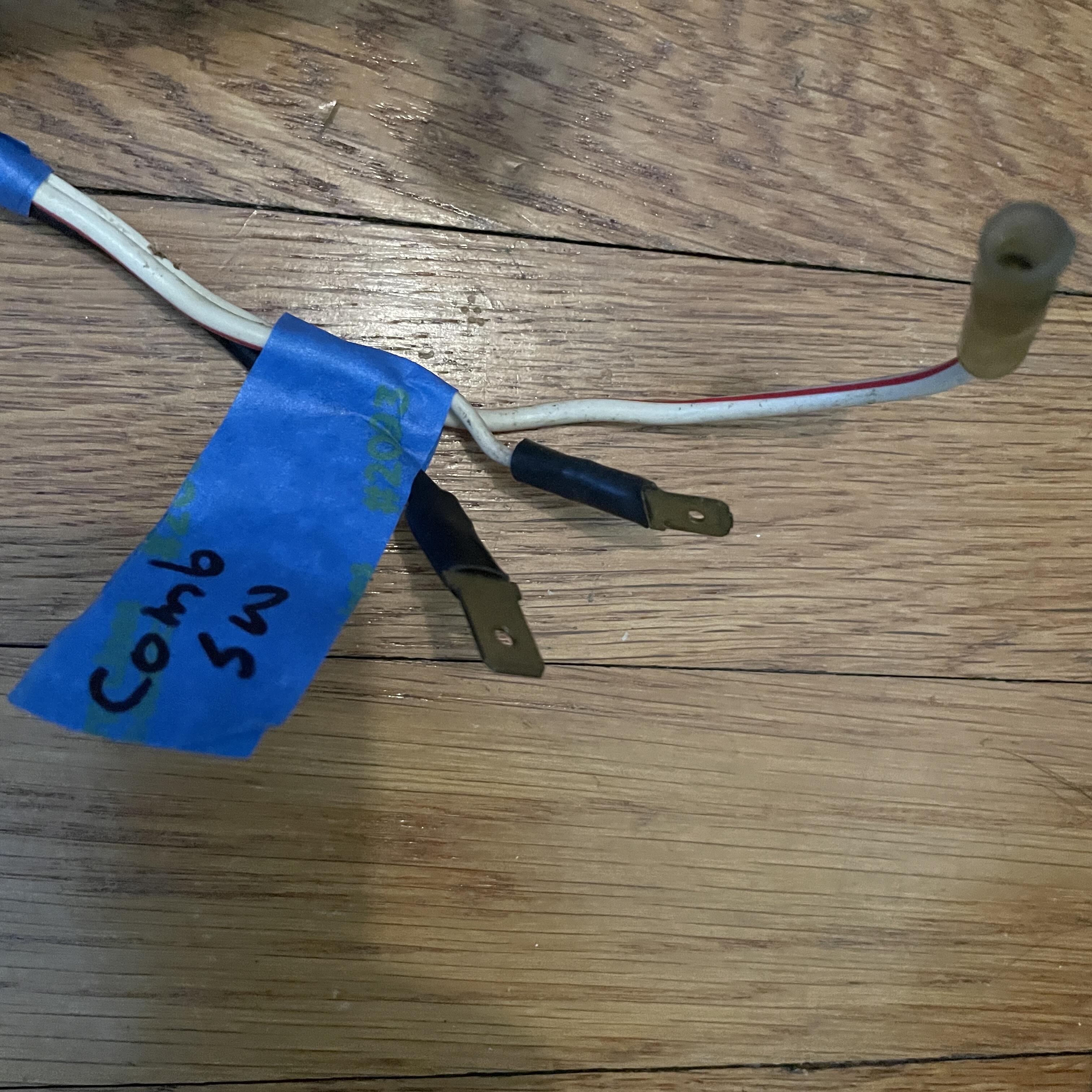
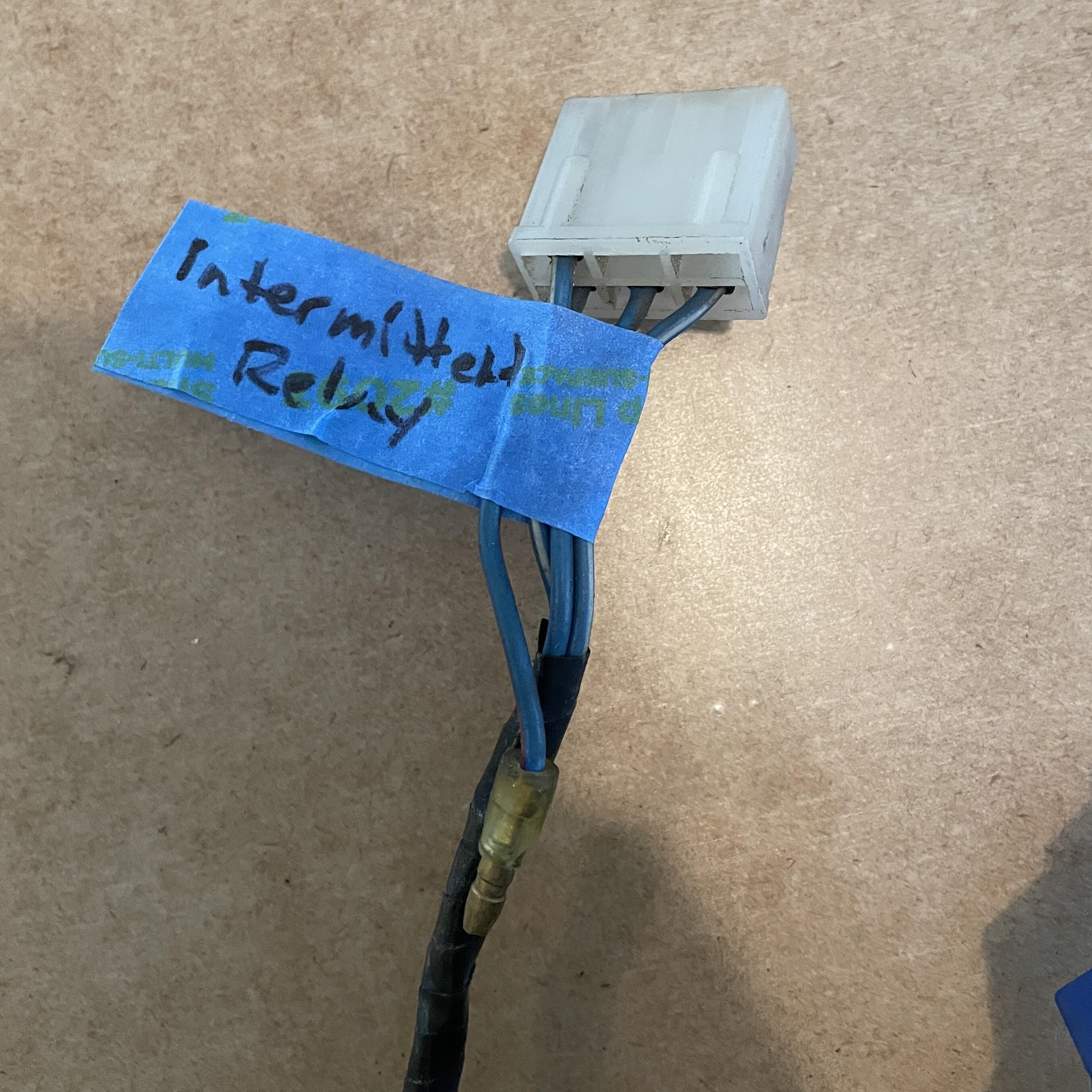
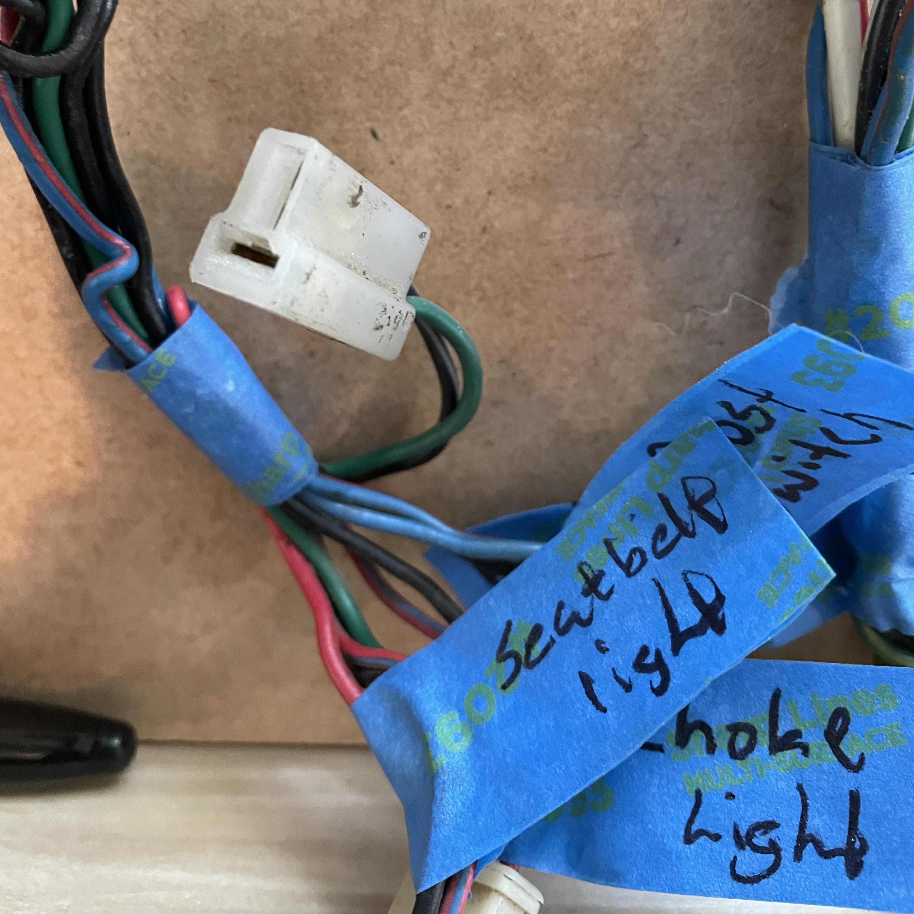
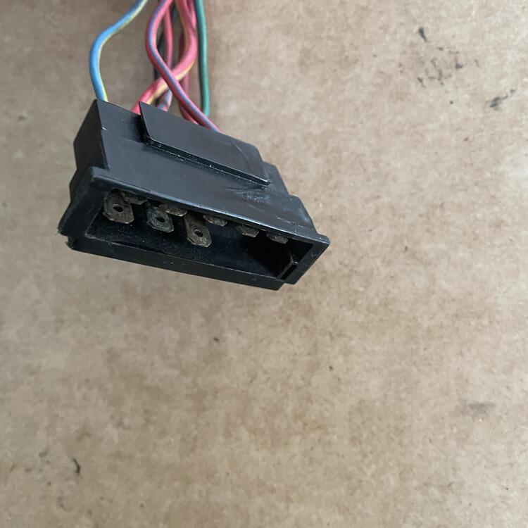
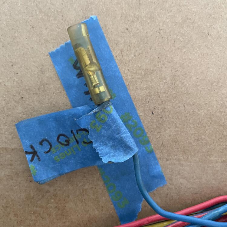
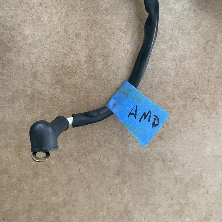
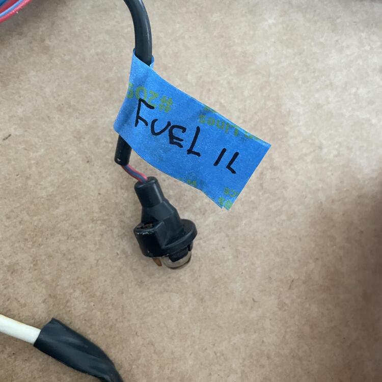
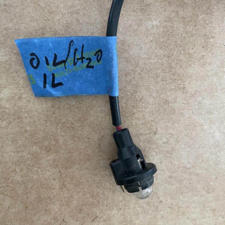
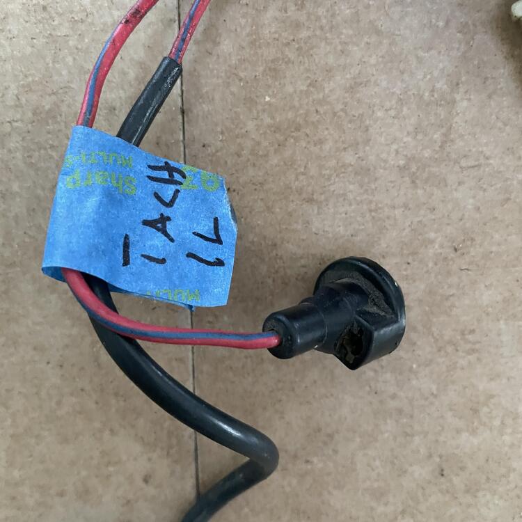
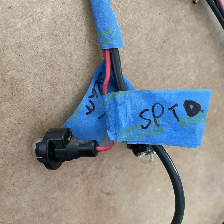
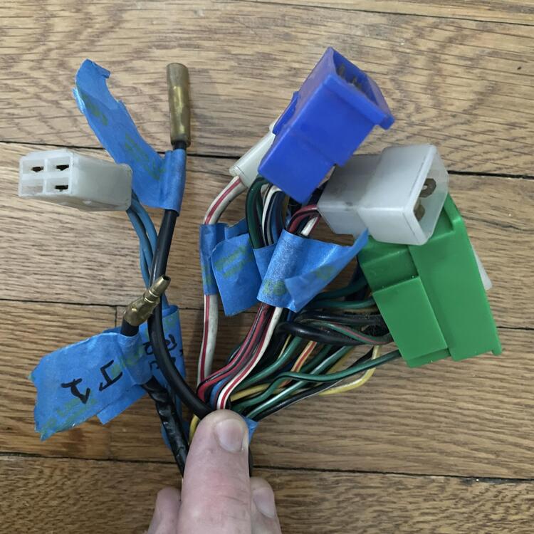
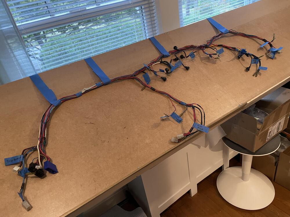
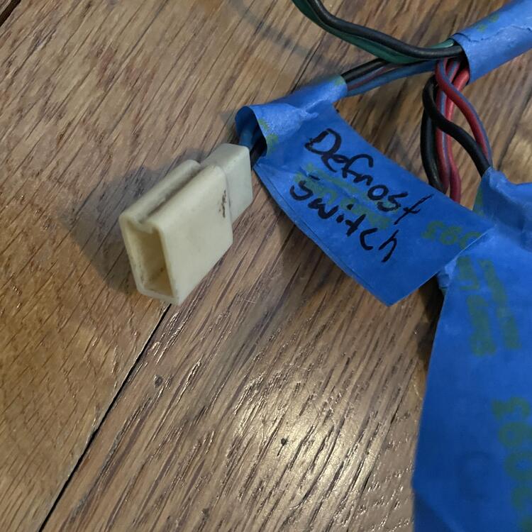
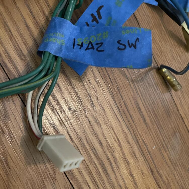
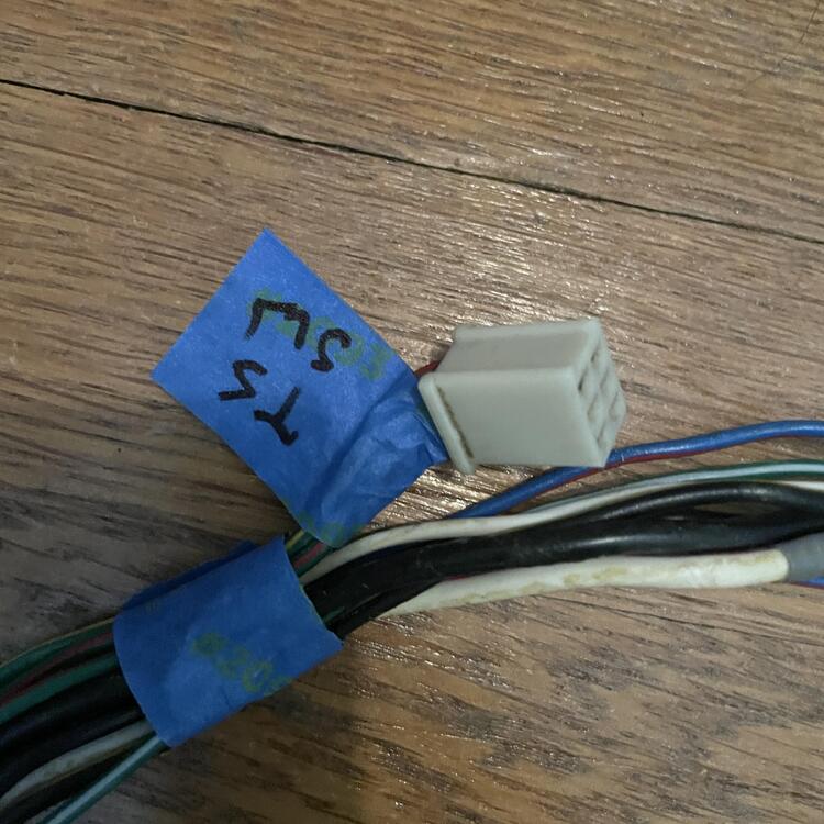
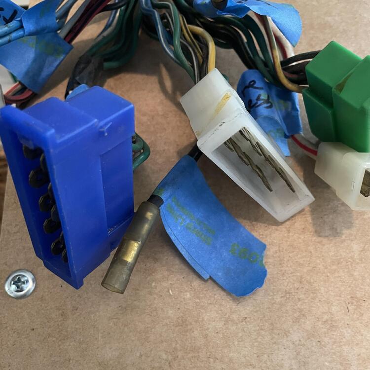
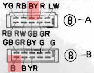
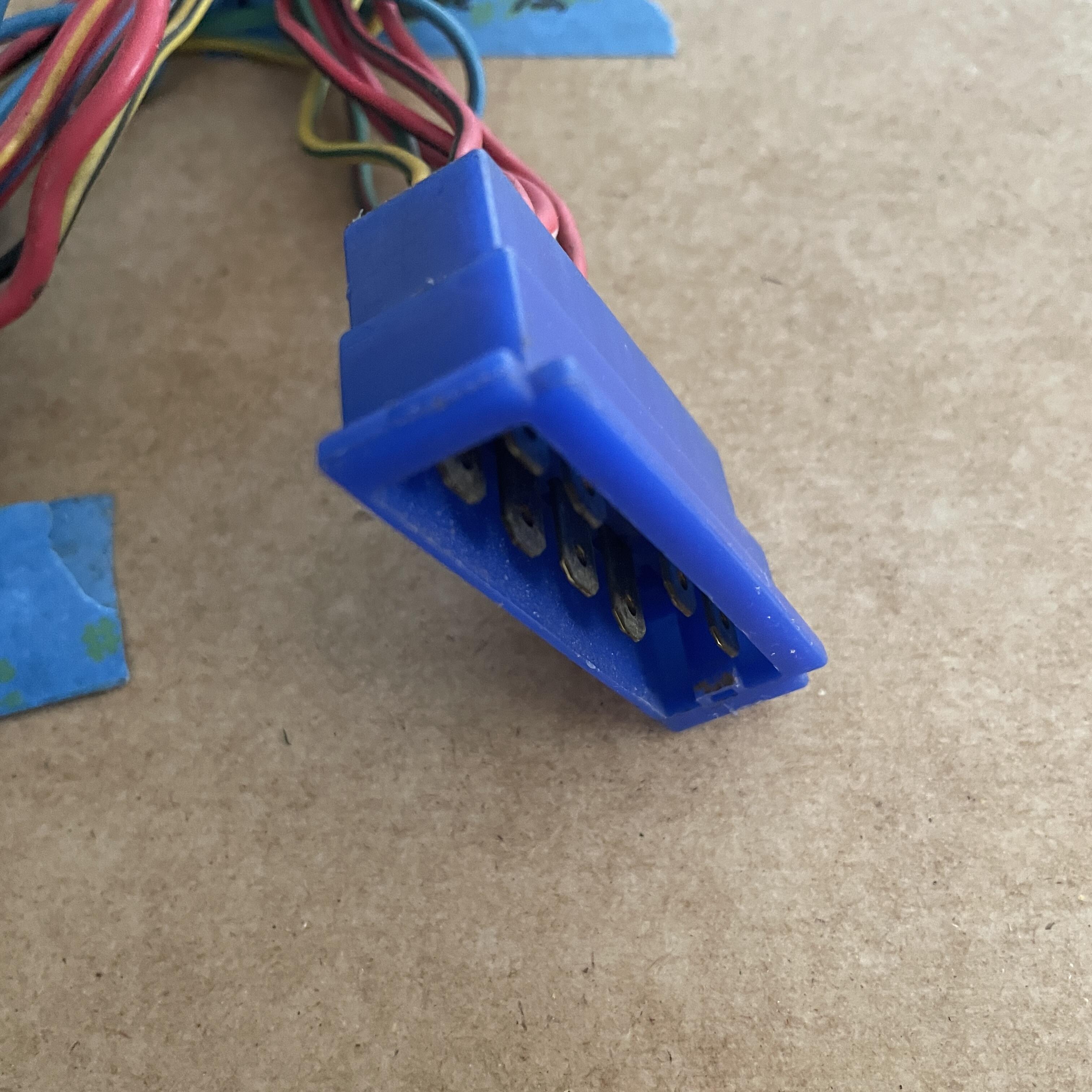
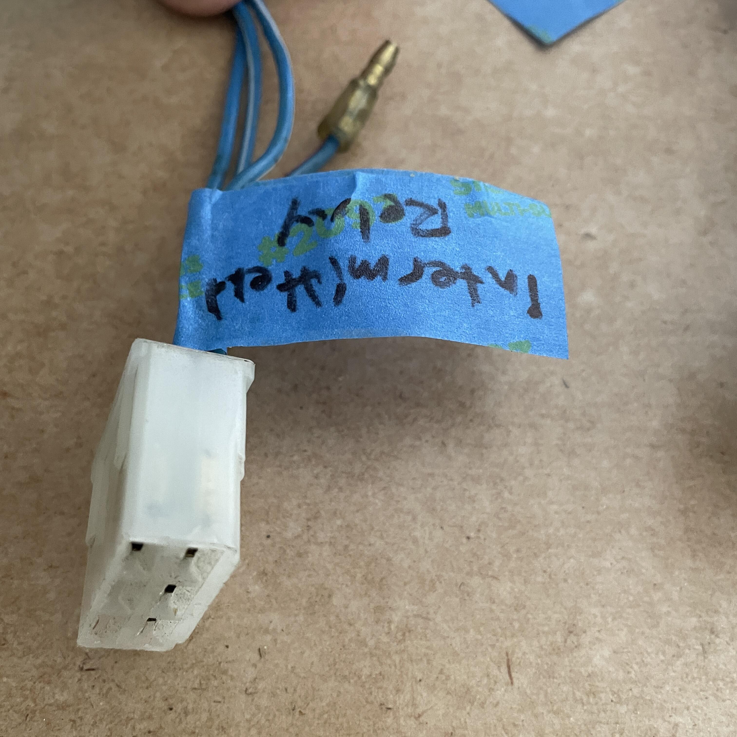
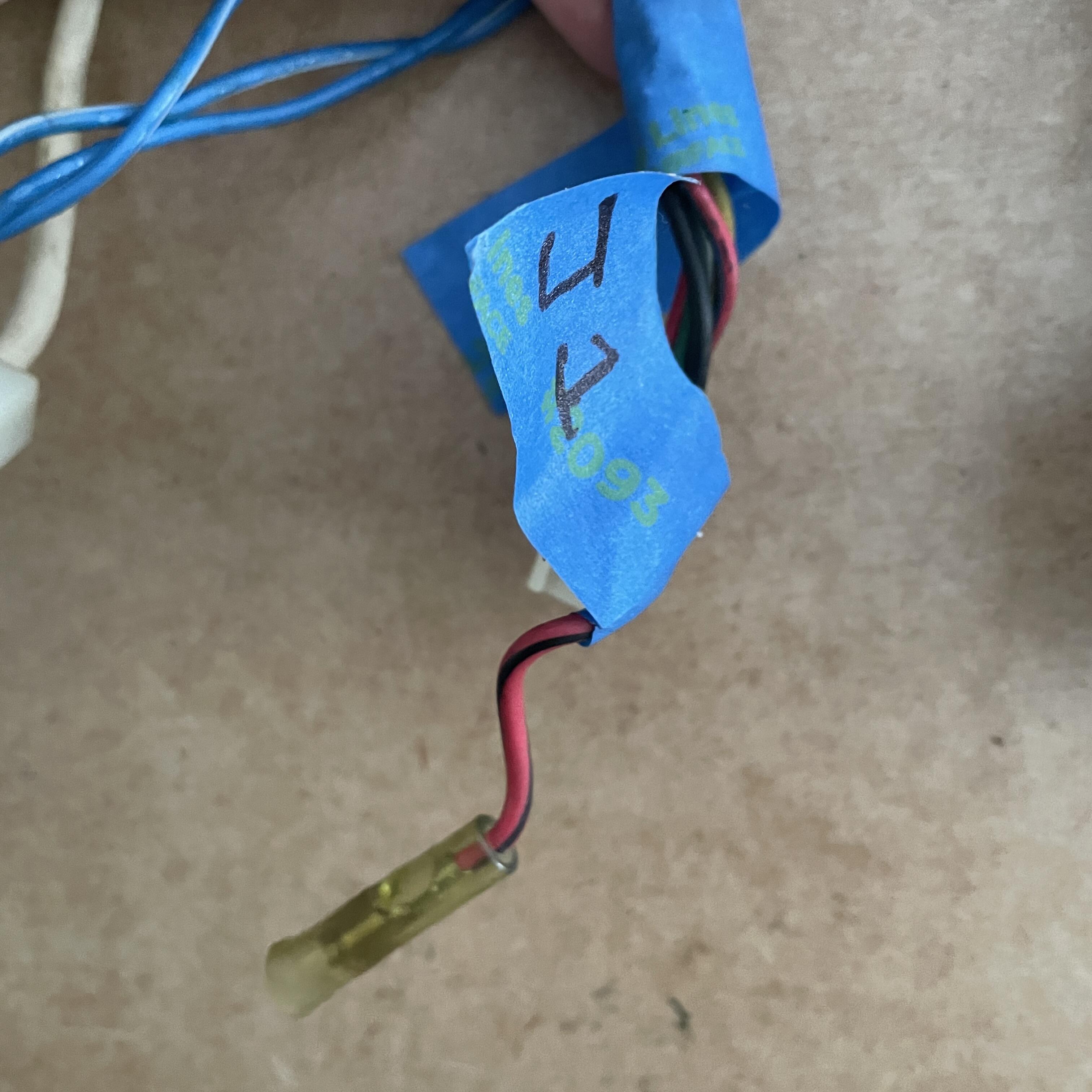
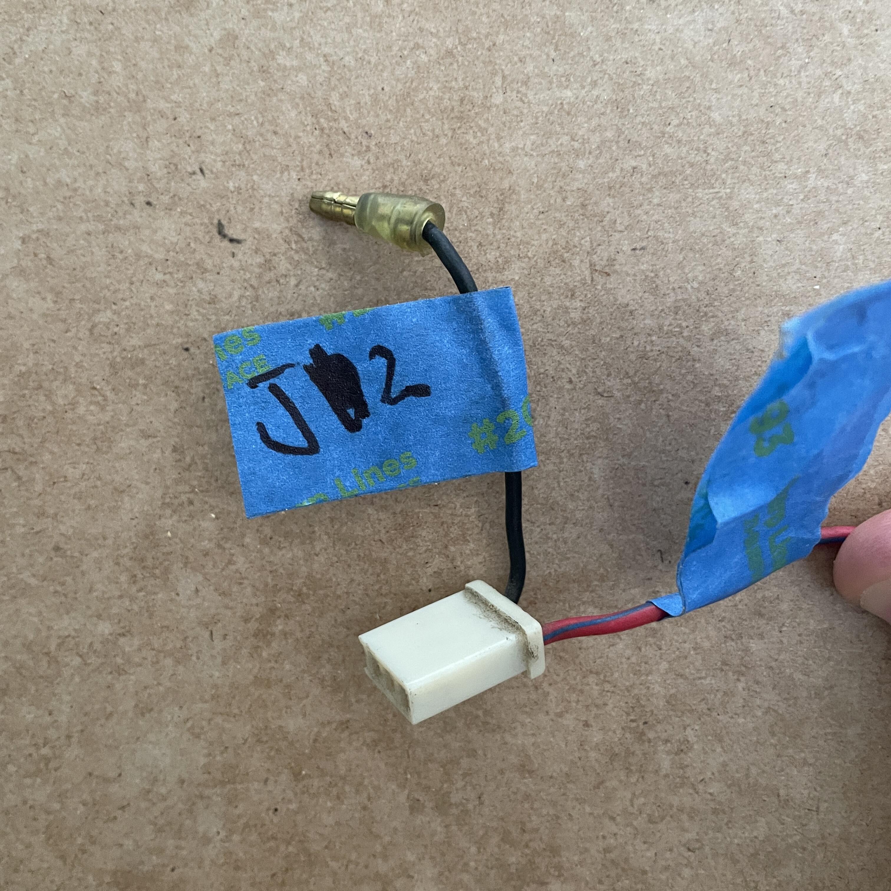
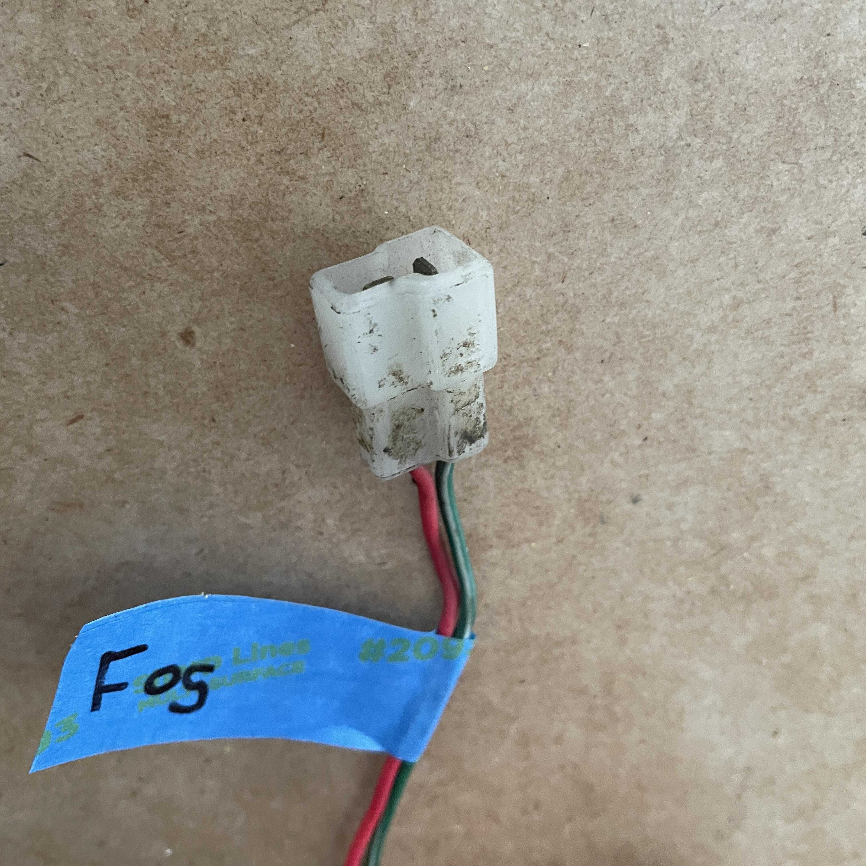
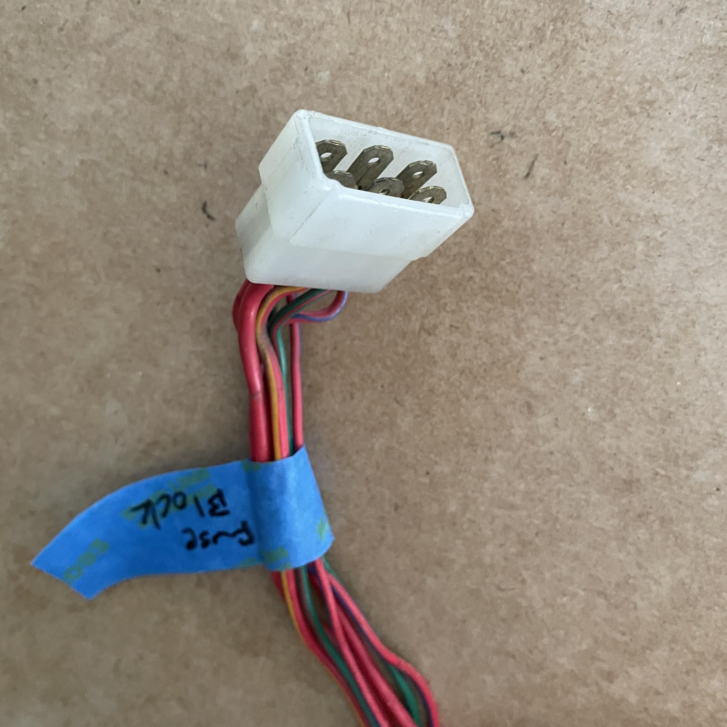
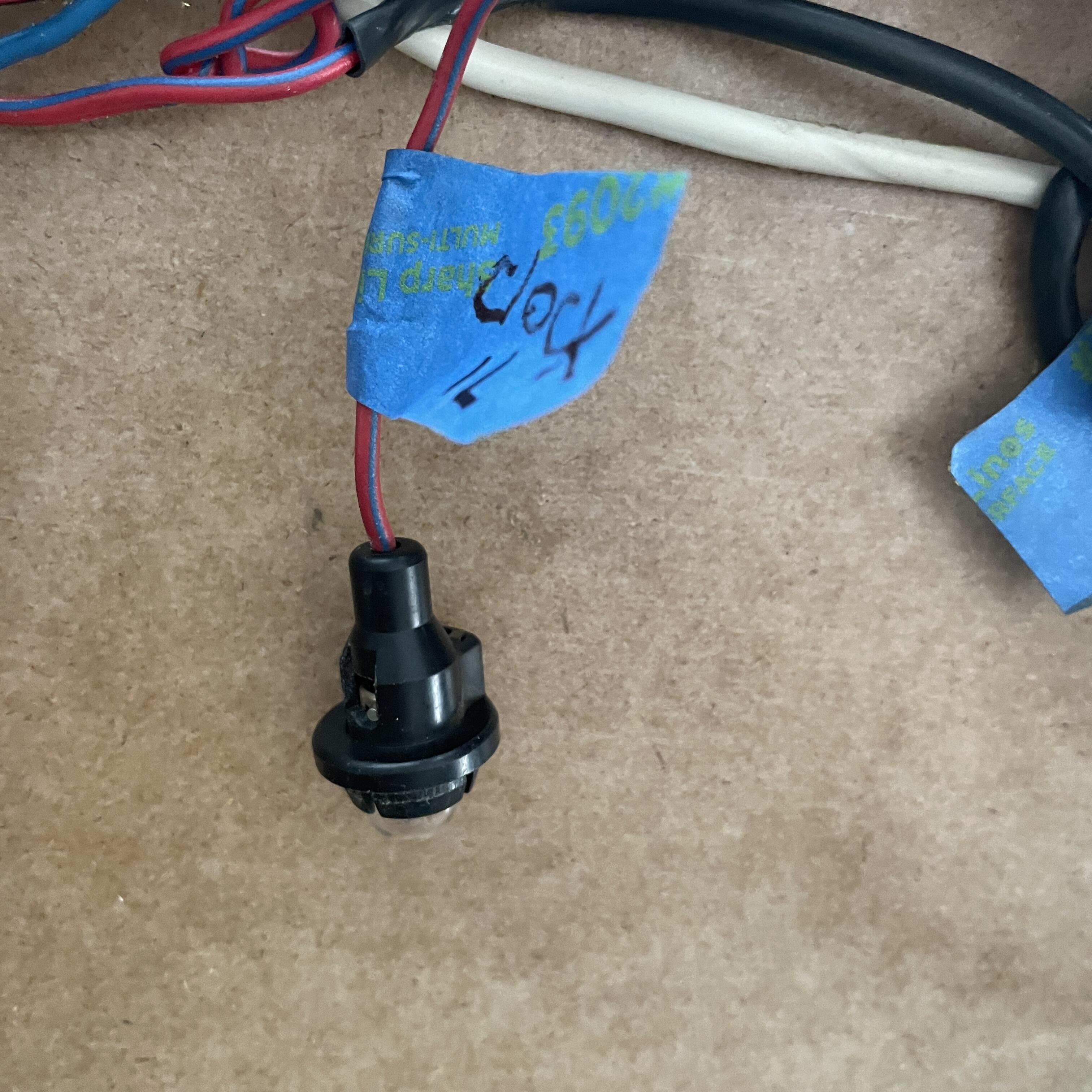
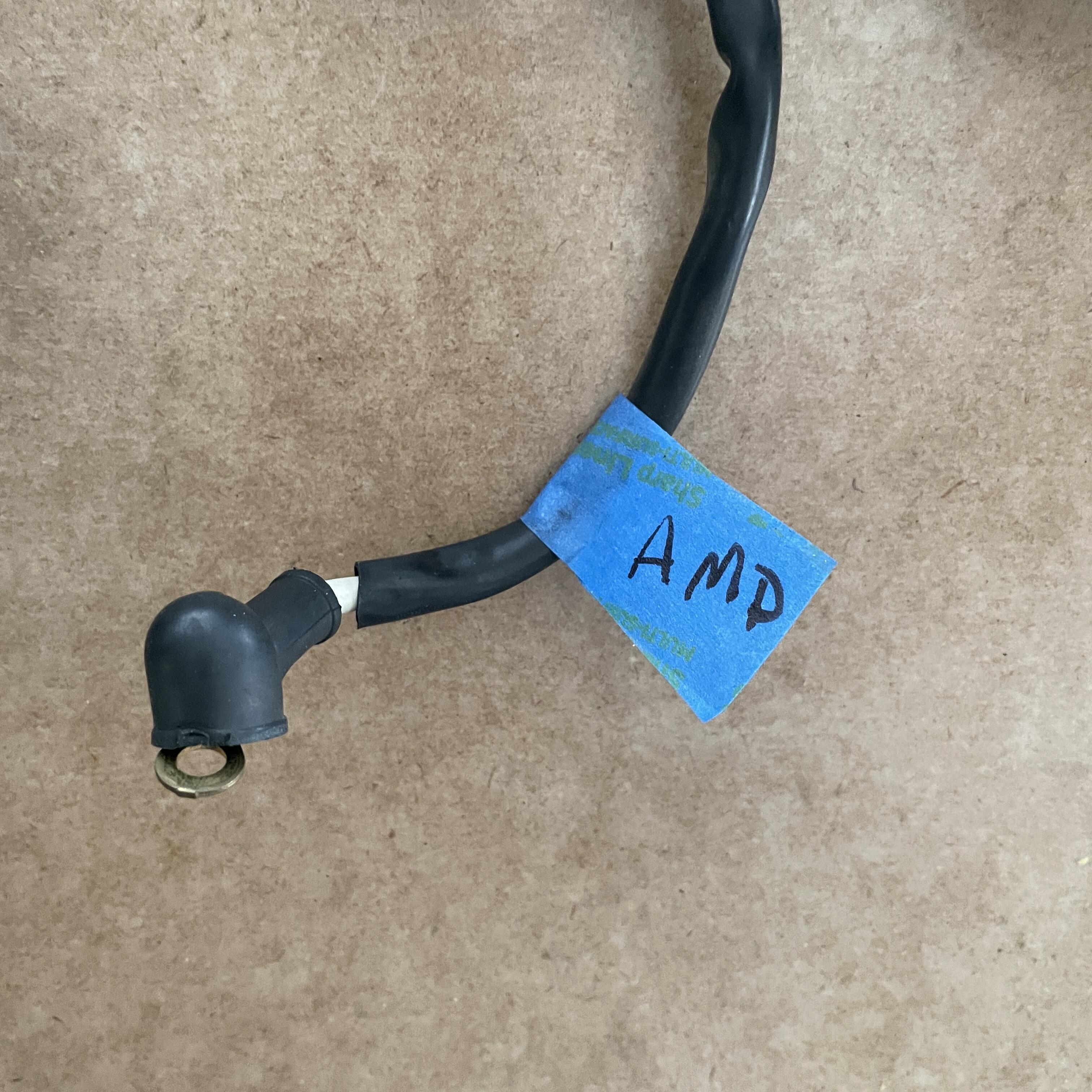
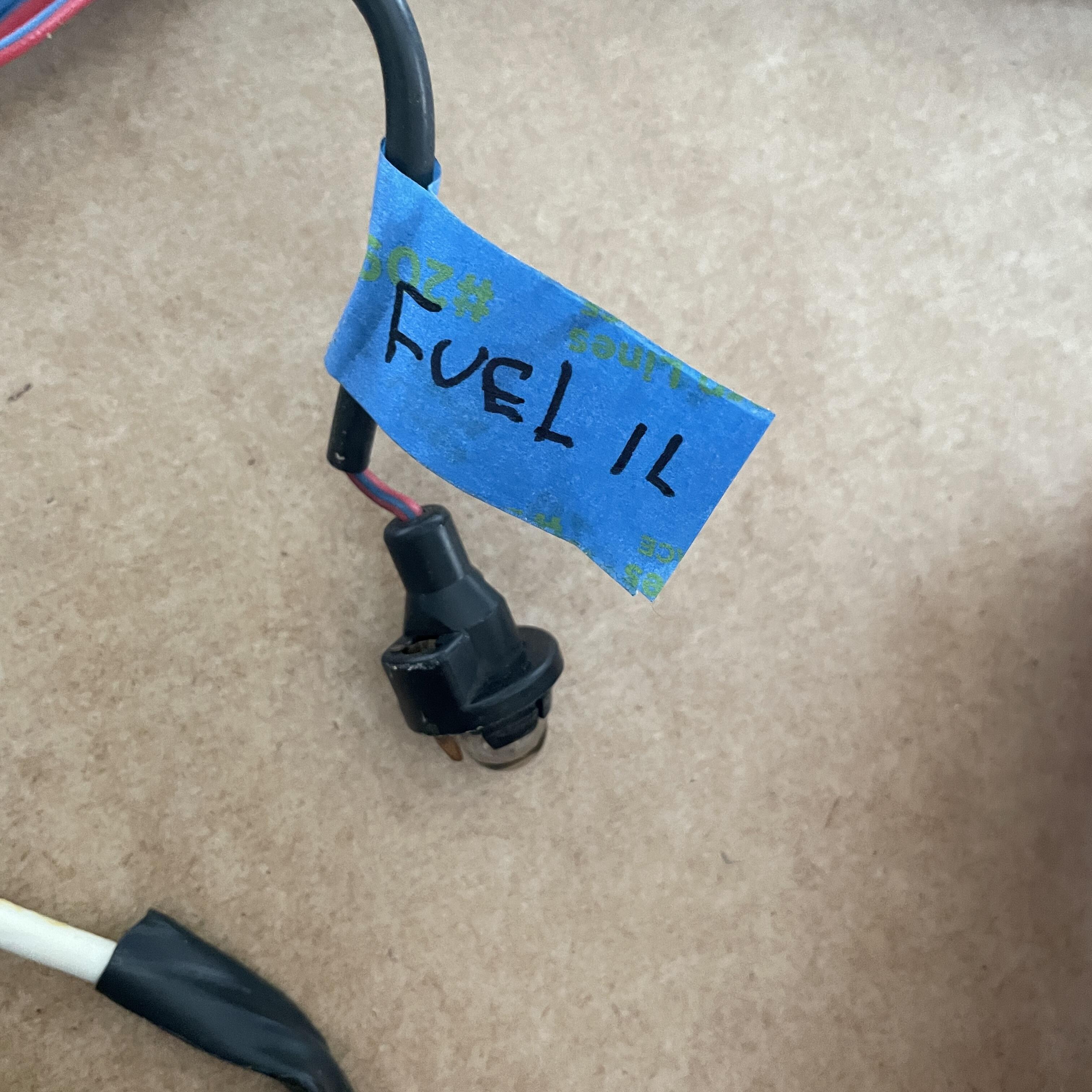
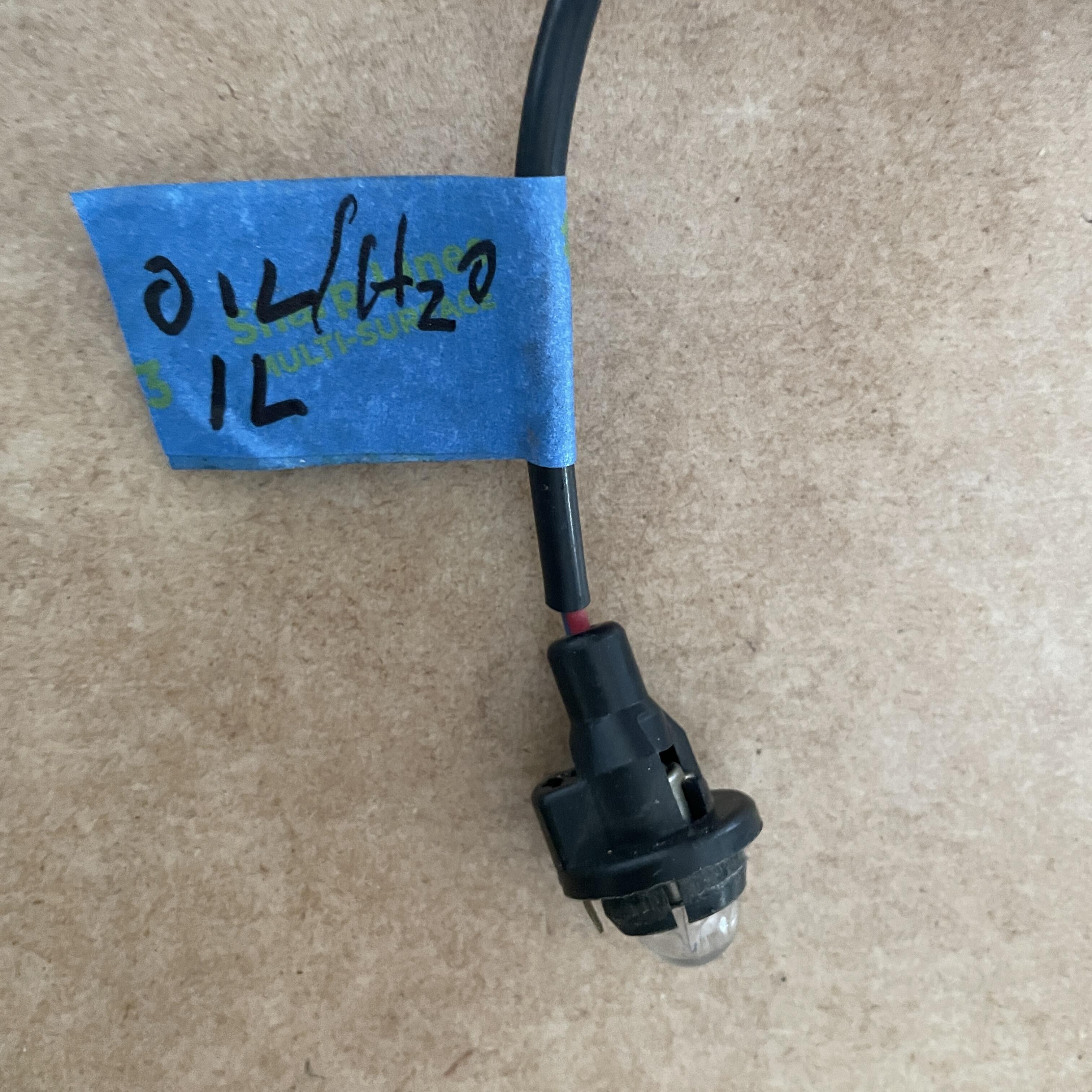
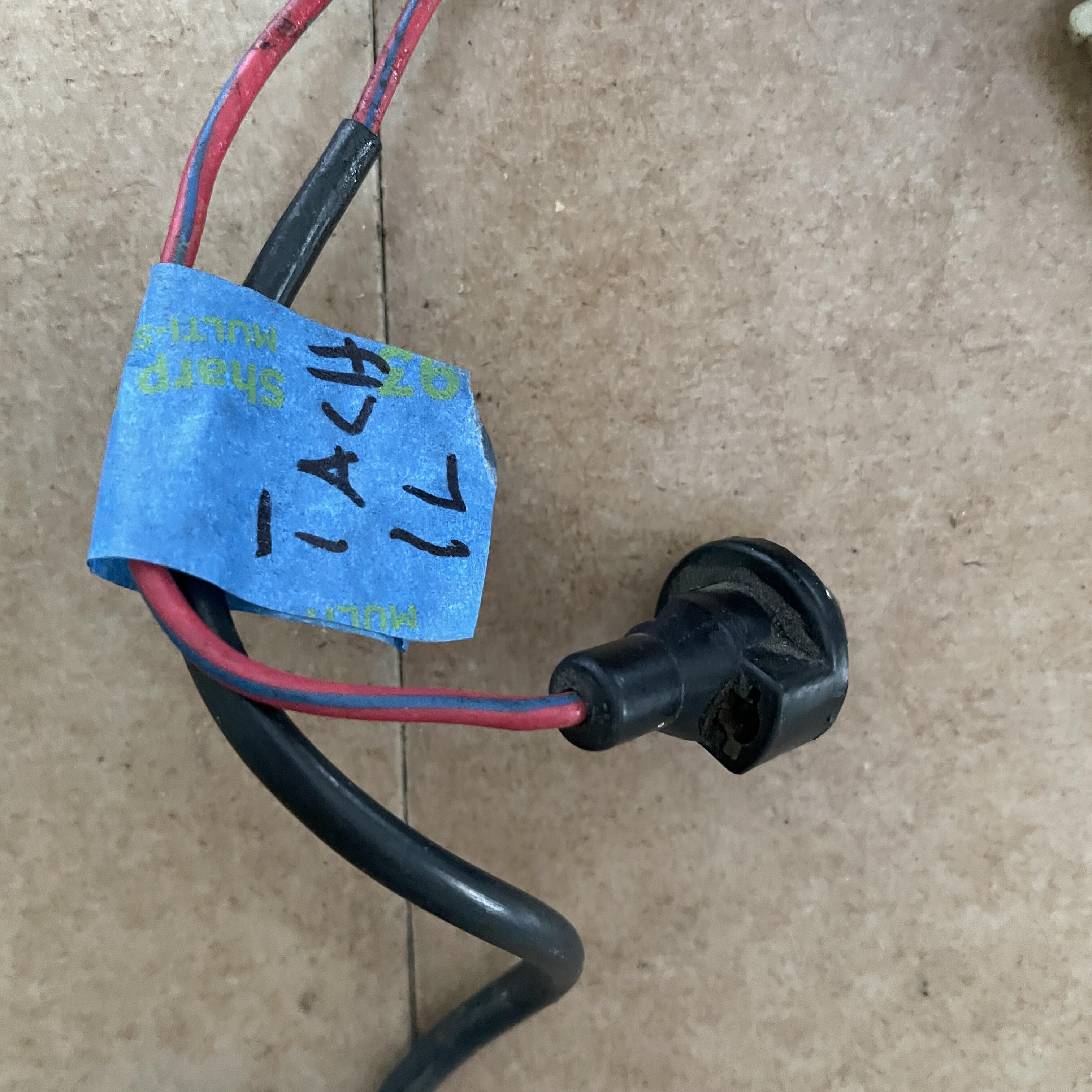
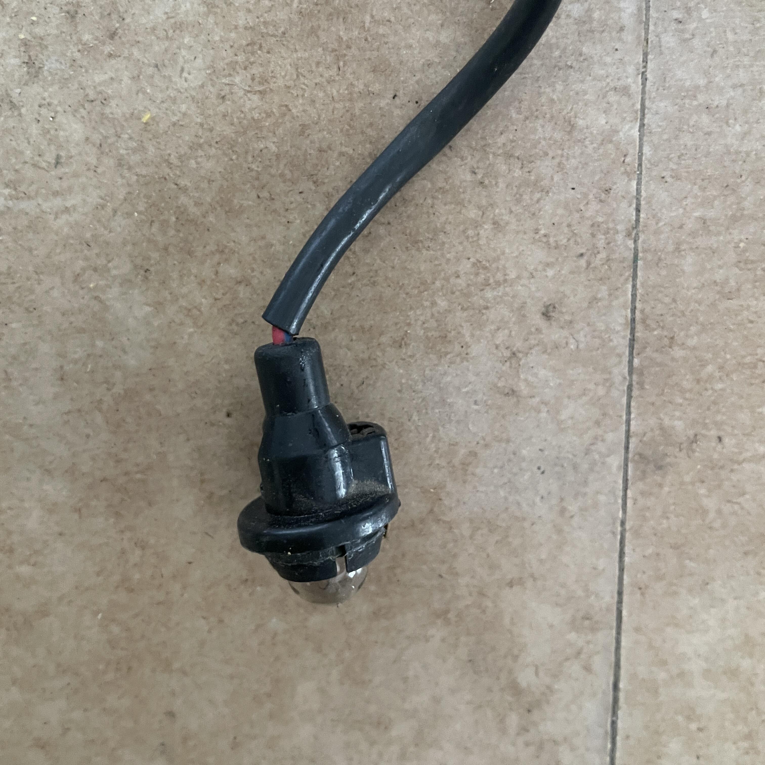
Okay, this one is going to be a long one, so I will try to bust it up into pieces to keep the conversation organized, because the dash harness (or harnesses, as it turns out) was a doozy. In one way it wasn't as tricky as the engine, because it is the correct harness for the car this time, but it was trickier in another way in that there were few things I could identify before I disconnected them (being disconnected when I bought the car) and the ones with spade and bullet connectors are not in the FSM Body Electrical section, so I am juggling between several years of FSM, the diagrams I downloaded here, and lots of Google searches. For the purpose of clear communication I will refer to both of these harnesses as halves of the larger "dash harness." If I need to distinguish between them I will refer to the one with all of the lightbulbs as harness #2 and the other one as harness #1, since their part numbers are 24013-M3322 and 24013-M3321, respectively. --- @SteveJ, @zKars, @Zed Head, and everyone else, I am hoping to enlist your help in identifying at least some of the things I couldn't figure out so I can fill in the blanks in the table. Hopefully some of you will know what these should be. Condenders are the 4-way flasher, heater, air conditioning power, resistor, fog light switch, and wiper motor. Missing Wires: In capturing the wire mapping from the FSM, I found that my harness is missing a black wire with a yellow stripe from the blue connector, and a black wire from the green connector (not the heavier gauge wire that goes to the combination switch). After reviewing the FSM and the diagram, the only black and yellow wire running through the dashboard I see is the one from the ignition to the starter (via the inhibitor switch in automatic cars). I have accounted for that one and it is in a different connector. The black one could be anything, really. I don't have any black wires missing on the other ends that I can tell. Unidentified Connectors #1 & 2: There are several places there the two harnesses connect to each other via bullet connectors. I have figured out what almost all of the bullet connector are throughout the whole harness except for a few on each half. OF the first two, one is a male bullet on the end of a 3-inch blue wire with a red stripe exiting Intermittent Relay plug. The other one is a female bullet also on a blue wire with a red stripe going to the fuse box. #3 (Harness 1): Next is a 3-pin connector with 3 wires (White w/ Black, White, Blue) on the branch that goes down the center console to the fuse box. The blue wire has a blue sleeve on it that may or may not be a repair from the previous owner. This one is right next to the connector for the antenna motor (left side of the photo above), so I thought this might be for the radio, but I have that one accounted for. There is no component on the wiring diagram with this combination of wire colors, as far as I can tell. #4 (Harness 1): This one might be power for the Air Conditioning, or it could be for the heater. There is a blue wire branching off the 30-amp fuse in the diagram for that. The trouble is, that fuse should have a red wire coming off it for the blower fan, but I am not seeing that in this mess. I think this one is for the heater. #5 (Harness 1): Another truly perplexing one is this 3-prong clip with two black and one green wire. This exits the center-console branch along with the ones above, but it's about a foot long. No idea what this is. it's missing in the FSM and the diagram, and I don't see a component with this color combination. I think this one is for the buzzer. #6 (Harness 1): There is a blue wire with a white stripe right next to the connectors for the fuse box. I think maybe this one is for the four-way flasher, but I am not certain. This is for the fuse box. #7 (Harness 1): This 2-prong connector is down the console near the choke and seat belt lights. Wires are black with a white stripe and green. #8 (Harness 2): Again, on the branch going down to the fuse box, this time on the other half, there is a blue wire with a female bullet connector. Maybe this connects to the other stray blue with I thought was for the AC, or maybe this is for the heater. I have a feeling these two are for those two components, it's just a question of which is which. I think this one is for the AC. #9 & 10 (Harness 2): These last two are also on the fuse-box branch. One is a thicker white wire with a sheath and a female bullet connector (middle wire in the photo below), which should make it easy to identify, but I'm still confused. This one splices to the fat wire that goes from the engine harness to the Ammeter. This is also for the fuse box. The last thing I can't figure out is the 2-prong connector is the photo above. It is not in the FSM and I can't find a component in the diagram with this combination. Maybe it goes to the resistor, because I do have an unaccounted for black & white wire that I mentioned earlier on the other fuse-box branch, but they are both paired with other wires (green / red) that are not showing in the diagram for that component, so I don't think so. Anyway, that's what I have to figure out before I can wrap up this inventory. One thing all the Googling I've been doing is teaching me is there are a bunch of little harnesses I might be missing. I already know about the tail light, fuel pump, headlight, turn signal, and step light harnesses, but I just saw a center console harness I haven't seen before on eBay (may be for a 280z ¯\_(ツ)_/¯ ). After this one I'll do the fuel pump harnesses and research the others. Then I can move on to deciding which materials to buy to make the new one. Thanks in advance for any help.


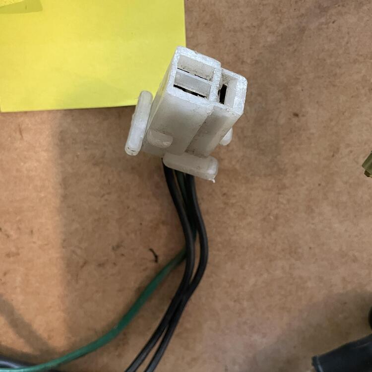


.JPG.7065247e31def03fa6cbe3df752c4895.JPG)
.JPG.37b4aee9c989f7aa64c0db983fad0905.JPG)