inline6
 Subscriber
-
Joined
-
Last visited
Everything posted by inline6
-
 @BoldUlysses: What paint (manufacturer of the 901 Silver) did you go with? I tried asking for Glasurit/BASF/Limco, and they had no formula/code for it.
 -
Oh man... the latest pictures of the carpet, aftermarket floor mat, and jute padding are gold. More pics saved to hard drive.
-
So, I just got back from the local auto body supply place - they carry various brands including BASF/Limco/Glasurit. I asked for Nissan 901 silver, and the guy looked up the code and found nothing available from Glasurit in the 55 Line, and nothing in the other BASF products. I found this online tool, and I get only 90 Line, which is water based. https://coloronline.glasurit.com/index.php?language=8 I think that is incompatible with all my Glasurit stuff... which I have on hand. I've got a lot of money invested in Glasurit primers, and clear coat (I did some work on my BMW M3 as well). So, this is kind of upsetting. Now, I find it hard to believe that I can't get to a Glasurit version of 901. Any ideas? I searched and found these somewhat related threads: I also could take the tool doors to the auto body supply place and have them scan it with their Glasurit scanner, but the comment in the one thread says that silver (on the tool doors) isn't the same as what was used on the outside of the car, and that seems like it should be unnecessary. Anyone have experience with taking a code in one manufacturer's paint and crossing it with another manufacturer? My other Z is a really pretty silver, and looks like the one in the image for the link to the thread above to me, but it is a Toyota (1987 Supra) in Glasurit that I asked for over the counter in 1994. Here is a pic: Garrett

-
Also, you should remove the chunks of body filler, or seam sealer or whatever it is (like above outer corner of right hinge) so that the hinges can be moved as needed. It looks like on the right one, that blob is keeping the hinge from moving up, which it sounds like it needs to, in order to make the panel sit level with the body on that side. Left one doesn't appear to be "clean" of residual stuff either, so that could be limiting it's movement. Inspect your weather strips and the flanges they are attached to. It could be that the flange the main seal is on is bent upward a bit in the left corner. That right hinge has an R on it, correct? Can't tell from the pic. The hinges are pretty beefy, so I doubt they are bent... or the issue. The mounting flanges on the hatch don't move around easily either. Doubt that is the problem. So, how is the fit at the bottom of the hatch? Left side to quarter panel, right side to quarter panel, and rear bottom edge from side to side? If the left front corner is elevated, the left rear should be elevated also.
-
Yeah, need pics of the hatch to hinge attachment areas, and pics of the hinges with left and right marked. Also, pic with hatch adjusted as well as you can currently, with back edge at proper height would be helpful to determine how far out the whole thing is. Need to see gaps on all four sides...
-
Nice! Looks like very nice quality - both of them.
-
Interesting... Different than now. Thanks for that.
-
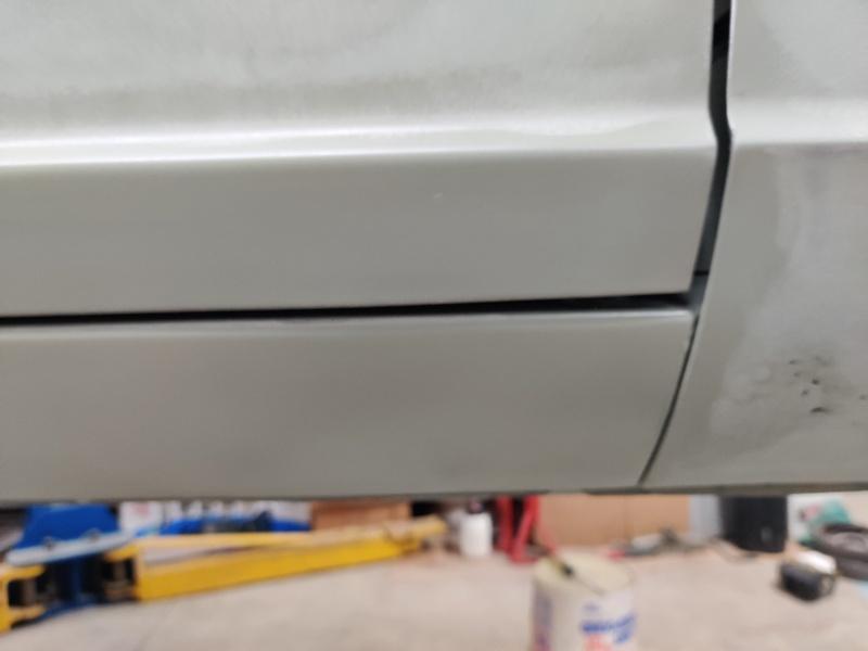
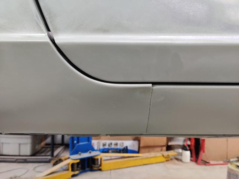
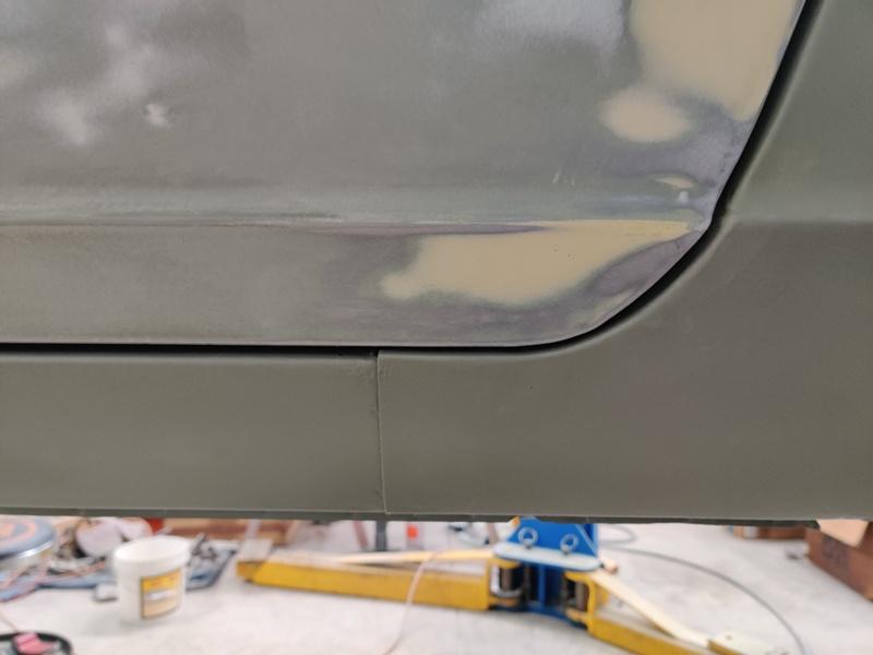
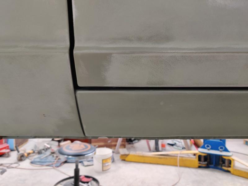
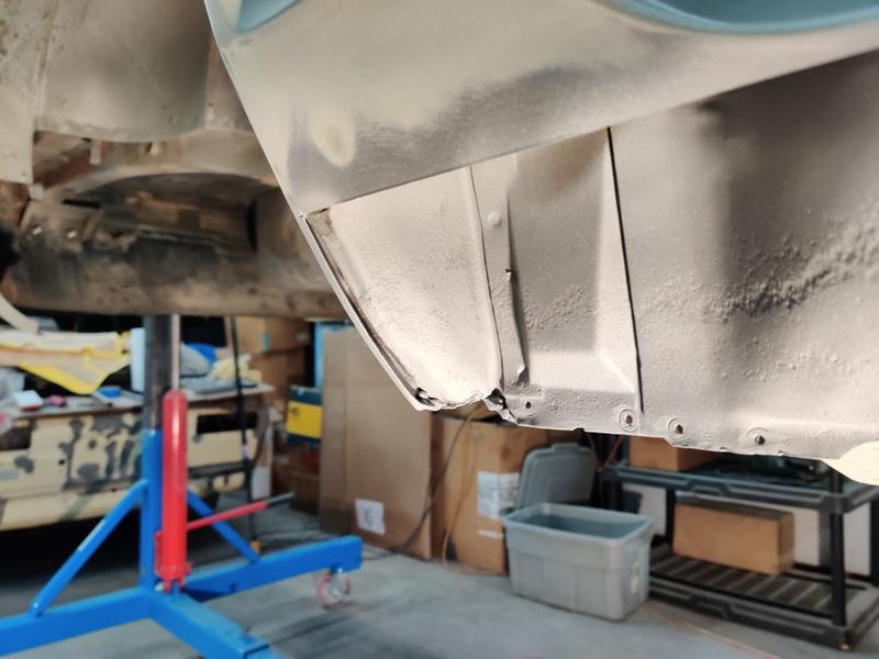
I find this rather interesting... and I am thinking about how to proceed. It seems that the panel gaps around the doors for this car are not ideal. This is likely a 240z thing or more precisely a 240z of my 240z's vintage thing... but I think the panel gaps here need to be worked a bit to be improved. Front of passenger door, bottom door gap line: At the front, bottom corner, the door panel edge rises upward a bit, increasing the gap distance between the door and the rocker: Passenger side, where the quarter panel dog leg attaches to the rocker, the distance across the gap to the bottom edge of the door is noticeably narrower than the distance across the gap from the rocker panel to the door bottom edge. Also, the door gap is inconsistent along this radius at the bottom, back part of the door to the quarter panel. Driver side, where the quarter panel dog leg attaches to the rocker, the distance across the gap to the bottom edge of the door is noticeably narrower than the distance across the gap from the rocker panel to the door bottom edge. Also, the door gap is inconsistent along this radius at the bottom, back part of the door to the quarter panel. Front of driver door, bottom door gap line: At the front, bottom corner, the door panel edge rises upward a bit, increasing the gap distance between the door and the rocker: I believe I have a bit more door alignment to do with the driver side door, so that the gap distance for the front of the door is the same as the gap distance on the bottom of the door. However, I also think I will be adding a bit of weld bead to the bottom front edge of both doors and shaping the added metal to eliminate this issue. For the quarter panel areas, I've already started doing minor surgery in the corner of the dog legs to improve door gap in that radius. This is visible in recent posts of the passenger side work.
-
I hear ya, but something has changed then, right? I mean, now, a new car doesn't take as long to get to the dealerships, but it could sit for months without selling. A new car made in 5/2019 that sits on the lot and doesn't sell until yesterday, is still a 2019 model. Period. Was it really different back then, such that when it sold, that is the year the car became? Doesn't make sense to me. I snagged a bunch of pictures of the paint marks in particular. The car I am currently restoring isn't as early a VIN, but hey, these are some great reference pics.
-
Never have understood the some cars with date stamps prior to 9/1970 are 71's. Can someone explain it? 5/1970 is a 1970 car... it's gotta be. Interesting how they used eBay to drum up buzz for the Bring a Trailer auction. Violates their rules for sure and I'm sure will be taken down. What a reference for paint markings! Really astounding - this car. Never seen anything like it.
-
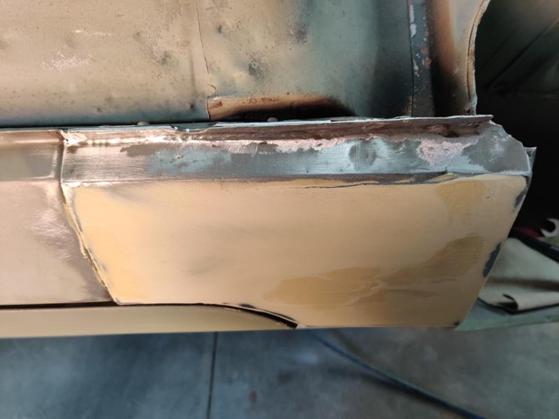
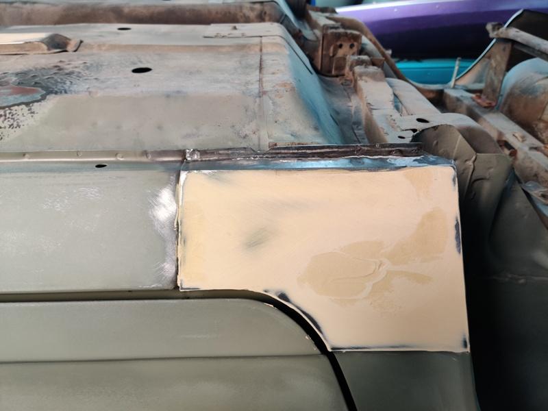
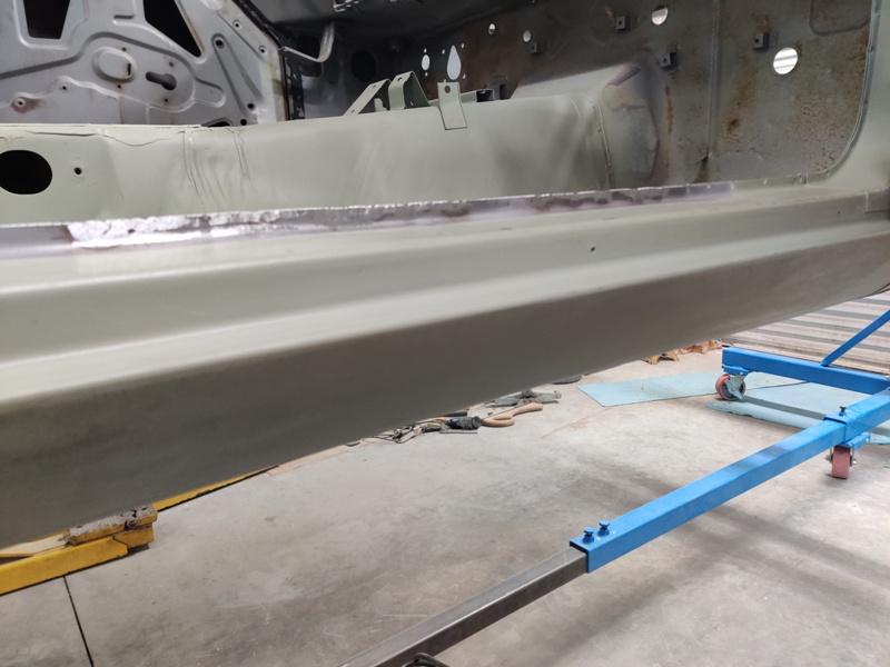
Thanks! Best I could do with the Mig and grinding. Maybe I'll be able to do this kind of thing better with the Tig in the future. And here is where having the car on a rotisserie is so nice! Still body filler art involved with making things straight. Much work work to do... Sighting down the body line, it is pretty straight. Next up (second pic) is to fix the floor panel where it wraps around and didn't get welded to the inner rocker right: More body filler work is ongoing. I hope to put a bit more epoxy primer on the body of the car tonight.
-
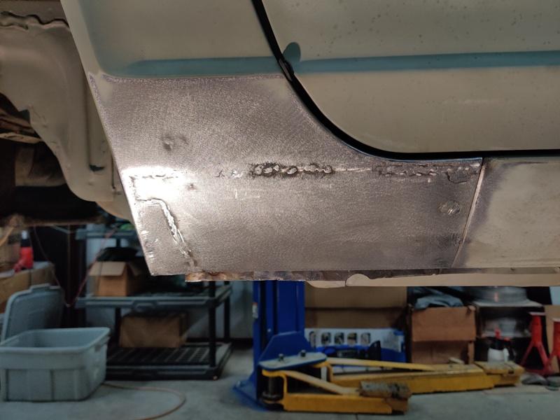
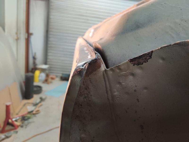
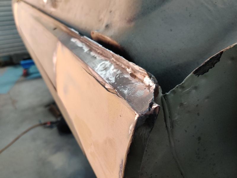
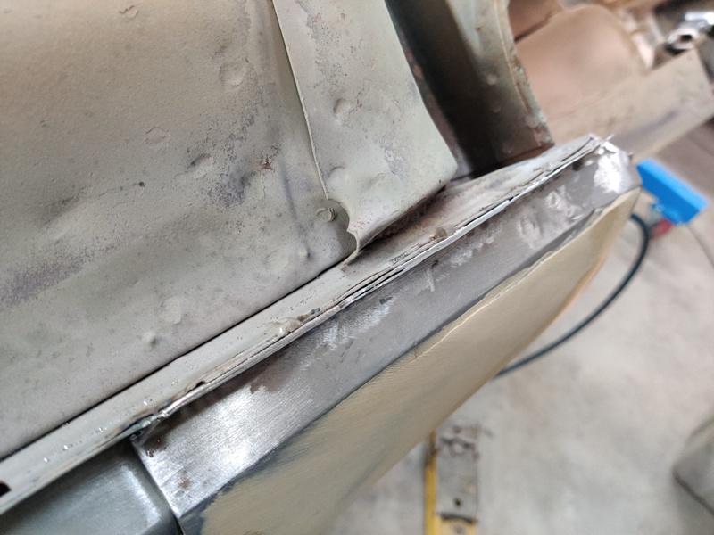
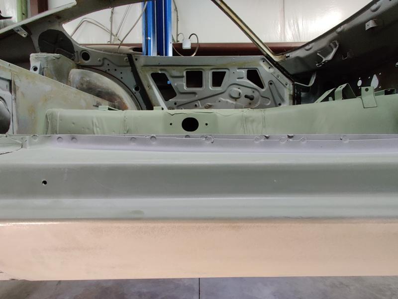
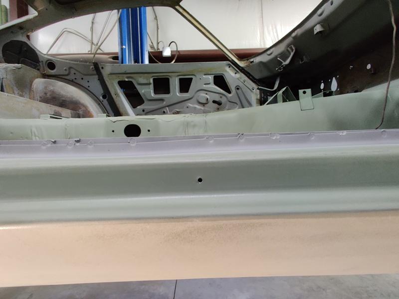
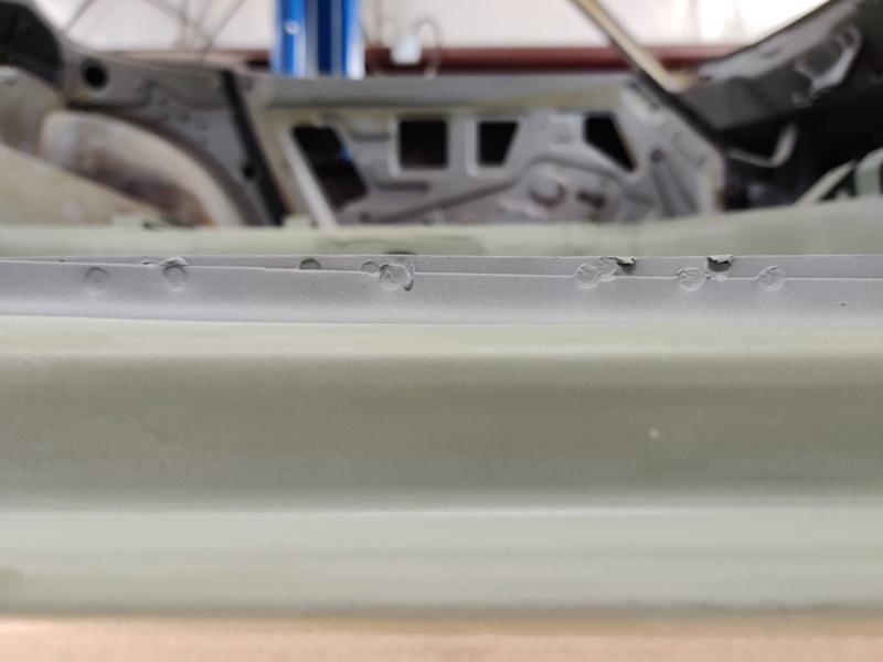
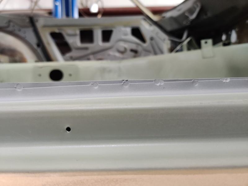
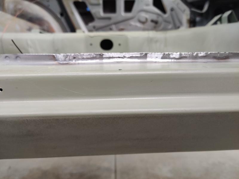
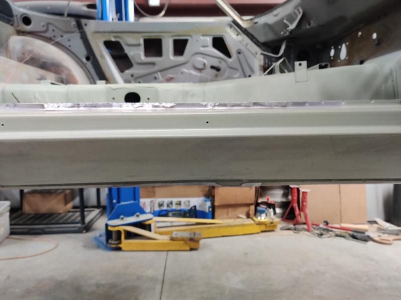
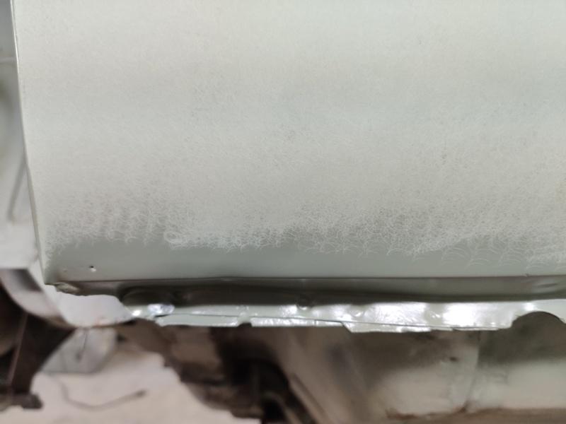
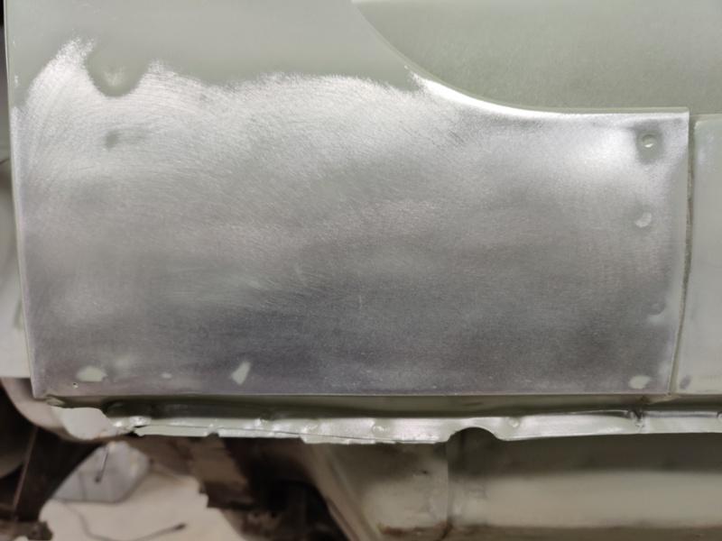
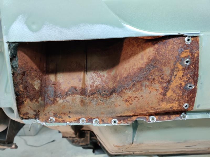
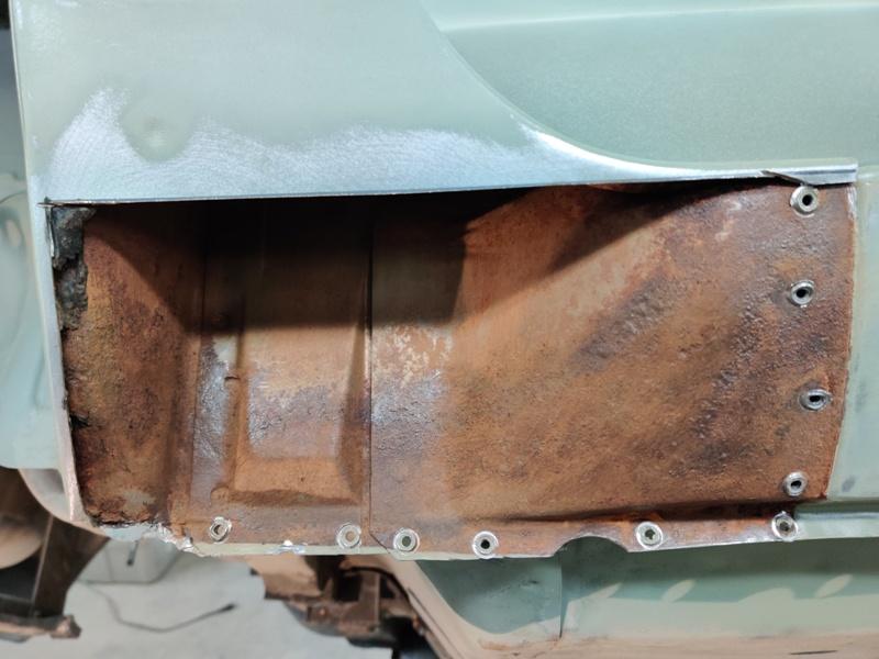
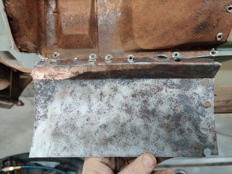
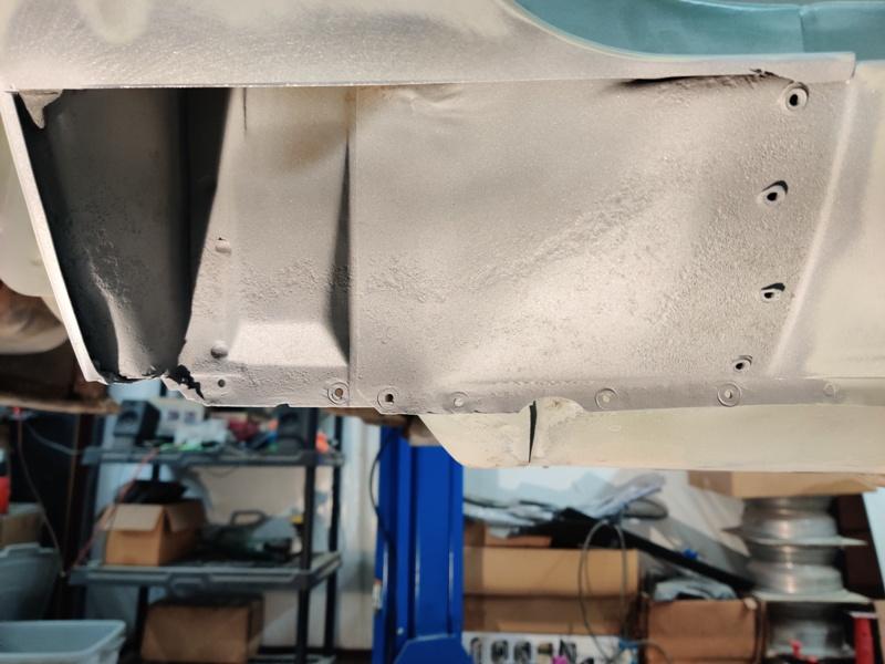
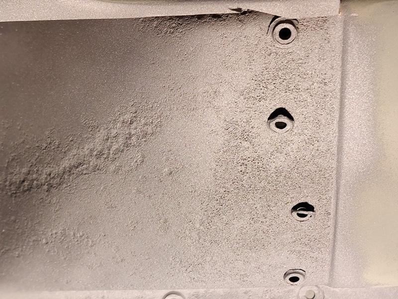
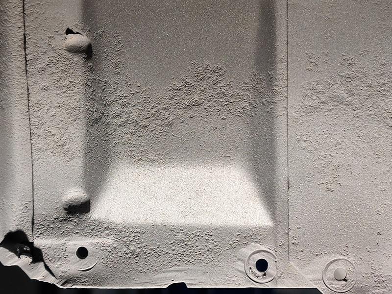
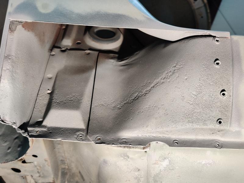
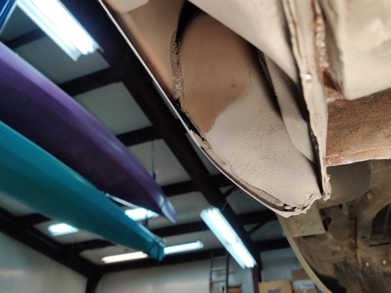
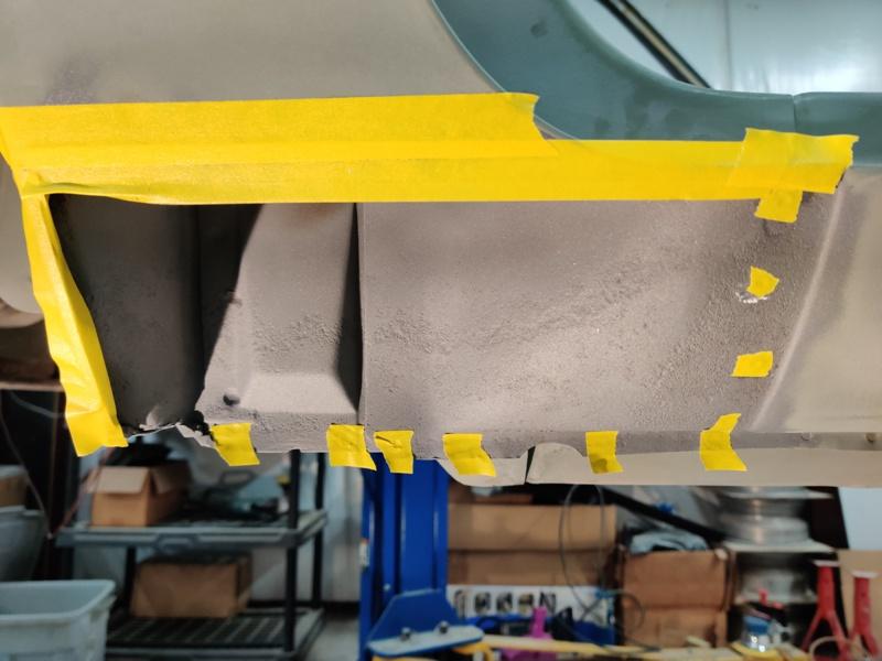
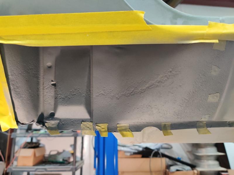
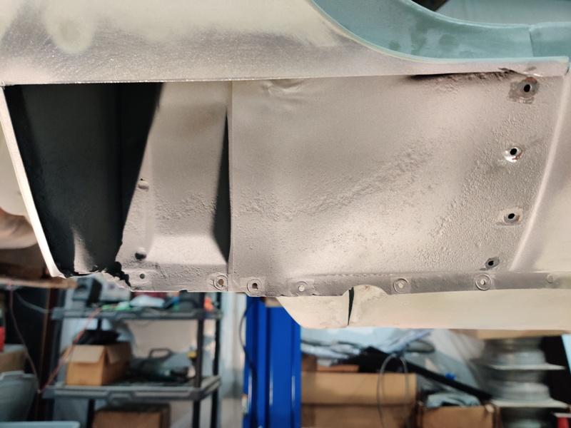
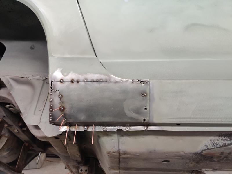
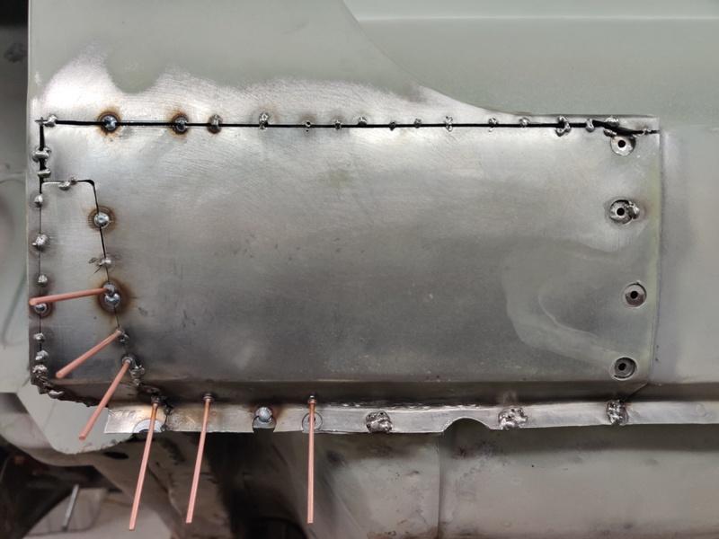
Work to straighten out the misaligned rocker panel (at the factory) has begun. In addition to the problem I already showed pictures of, the top of the rocker panel had some misalignment as well. The outer panel was noticeably low along the top edge, but only for the center portion of the rocker panel. This caused a dip in the top surface that the aluminum threshold goes over top of: You can even see where the spot welder completely missed in attempting to join the inner and outer panels. Seems the workers at the factory had to adjust the welder downward to hit the outer panel, and even then, they could only pick up the top edge. I didn't show how I corrected it, but I just drilled out the spot welds, then used the stud welder to put some pins on the weld flange, and then used a crow bar and piece of plate to protect the top surface of the rocker, while prying up on the pins. This allowed me to put enough lifting force on the weld flange to raise the low area of the rocker. I then welded, with my Mig, the holes left from cutting out the factory spot welds, and ground everything flat again with the surface of the outer panel's weld flange: It's not perfect, but it is much better. Metal work like this is a big time suck. Lots of tedious grinding of welds. I finished them off with my hand held belt sander. I hope to experiment with the spot welder I bought on this flange, but the electrodes may be too large in diameter to align well on this flange. We'll see. Next up was the part where the quarter panel folds over the rocker at the back. Interesting to see what is inside. After a light dressing with wire brush... and the outer panel piece receiving some attention in the glass bead cabinet: The sandblaster was again employed to remove corrosion and get to nice metal. Got several pictures while this area was seeing the light of day: Close ups showing pitting (light pitting, in my opinion): My first 240z was missing the entire dog leg corner (inner and outer). So nice to see this area in such nice condition. Pic showing up inside (bare metal from the factory and the seam sealer they used in the wheel arch). A few more minutes in the glass bead cabinet with the panel. The dark corner (upper left in pic) was pitted too much, so I made a section to replace that. Taping for application of weld thru primer. I've never used it before. It is kind of transparent (has been applied in second pic): Tape removed and outer panel tacking in progress with new fabricated piece also (bottom left) As the welding occurs, the panel wants to move around. I used the stud welder to yank on low areas, trying to keep alignment as best as I can as welding continues: Alignment is not bad. Lots of time involved with keeping alignment, tacking, and eventually grinding. I easily have more than 30 hours of time with fixing the rocker and removing and reapplying this panel. The end result of the main effort, to straighten the bottom of the rocker panel/quarter panel along the bottom of the car is "better". Sometimes I can't get things good enough to my liking. I've ground the welds in the last picture down and filled small voids etc. More pics will follow, but it's time to get out there and work on the car again. ?


-
View Advert 240Z hood, right fender, metal headlight housings All parts are OEM and in very good condition. If you would like more pictures, I can get them for you. Hood: Came from a 1972 240z. Acquired in 1993 from a car in Virginia. Very straight, stored indoors since the mid 90's (Still Available): --> $300: Fender (from AZ/CO area): pics of the fender after sandblasting the lower corner. One or two pin holes and some very minor rust pitting, but otherwise this is very nice. A fender like this saves you lots of time on body work prep instead of one you have to section in new metal, do metal work, etc. --> $250 plus shipping ****SOLD Headlight housings (metal, both left and right from AZ/CO area), all threads are in excellent condition - nice - rust free: --> $80 each **** SOLD Advertiser inline6 Date 01/03/2020 Price $0.01 Category Parts for Sale
-
Bump: Hood sourced from VA in the 90's is still available: $300 Headlight housings (metal) are reduced to $80 each Fender still available: $250 Ask questions if you like and I can provide more pics as necessary.
-
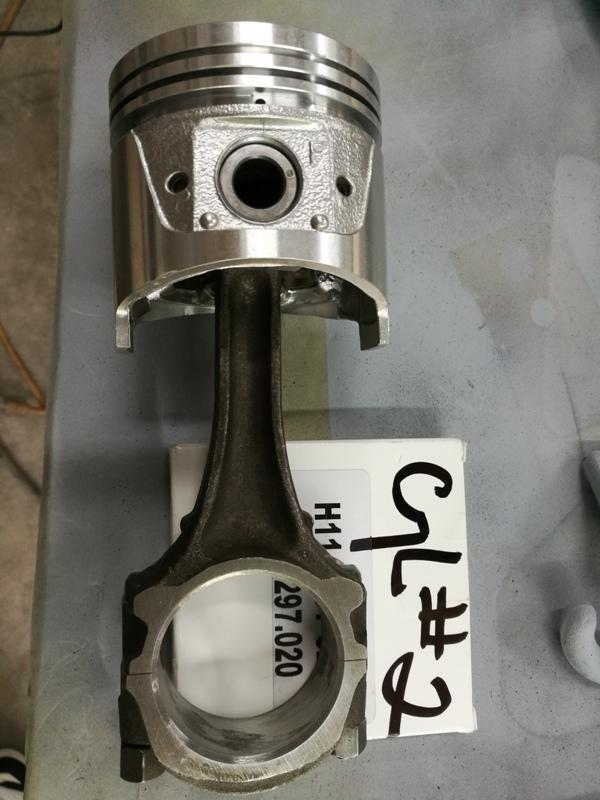
I got the head gasket - 11044-27LX1. I measured it in several places and it is mostly .057 to .058". I found one spot in the gasket only area that was .056". Across firing rings bridging 2 cylinders (measured between several sets of cylinders), I get about .059". 1.42 mm thickness was claimed in the eBay listing, and that is close to .056". So, if this gasket doesn't compress more than .009" upon installation... (.056" minus .025" (pop up) = .031", minus .022" (min. piston to head) = .009" allowable crush) then this should work.
-
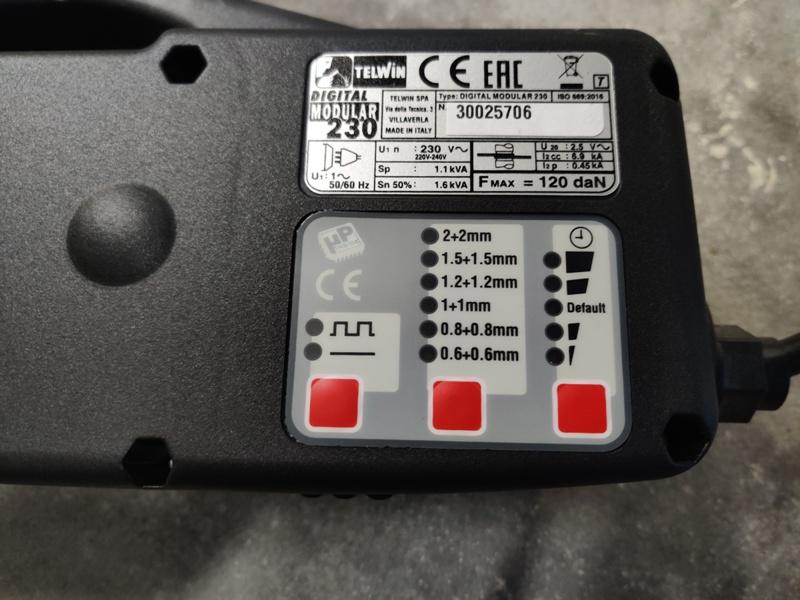
Thanks for this info. Very informative. Here are the specs of the Quick Spot II for reference. I am not familiar with kVA. Can you tell me how you arrive at 1.6 kVA? I assume an equation of some sort and some of the following as parameters? Quick Spot II Specs Maximum Welding Current: 6000 Amps Welding Voltage: 2.5 Volts Max Electrode Pressure: 265 Lbs. Input Voltage: 220 Volts Input Amperage: 30 Amps Maximum Absorbed Power: 13 Kw Rated Power: 2.3 Kw @ 50% Spots/Hr: 180 (continuous mode, 20 gauge panels) Maximum Double-Sided Spot Welding Thickness: 14 gauge (.075") + 14 gauge (.075") Dimensions: 17" L x 4" W x 7" H Weight: 30 Lbs. Warranty: 1-Year
-
Do you know if those dimensions were taken before installation or are they for used gaskets?
-
Thanks for the info. Got me looking again at this today. After looking around for information about stock head gasket thickness, I am still not sure I can know with certainty which of the available gaskets will work. In this case, I am focusing only on those head gaskets for a 2.4 L engine. I have a Fel-Pro on hand which came in an engine gasket kit with the car. I measured it a .045" thick for the most part, but at .052 across the fire rings. I am unsure if that gasket compresses when installed - perhaps it compresses at the fire rings only... It appears to be made out of a very hard substance as opposed to the OEM stock gaskets, which appear to have a soft coating which can compress. .045" would be a problem with .025" piston pop up, at least as I understand it. Minimum piston to head guidance I have seen before is .022". There are a few different part numbers for OEM 2.4L head gaskets, but availability (right now) looks pretty sketch. 11044-27L01 appears to be discontinued. There is one on ebay right now. And you might be able to source this gasket from overseas. It was apparently replaced by 11044-27LX1 which I just bought on ebay. It shows 1.42 mm for thickness, but who knows how accurate that is. And I expect this one will compress with installation. How much, I am not sure, but from looking around online today, I found people indicating .12 mm to .15 mm compression after installation of stock gaskets, which is 5 to 6 thou. I figure the gasket I just bought has a chance to work for me if the 1.42 mm and .15 mm is accurate. That puts the gasket at .050" compressed (again, in theory), which would give me .025" piston to head clearance. I think I will have silly putty on hand to check head to piston as well as valve to piston clearances.
-
Do you mean with the stock head gasket? That is about .019" piston to head clearance. That will work?
-
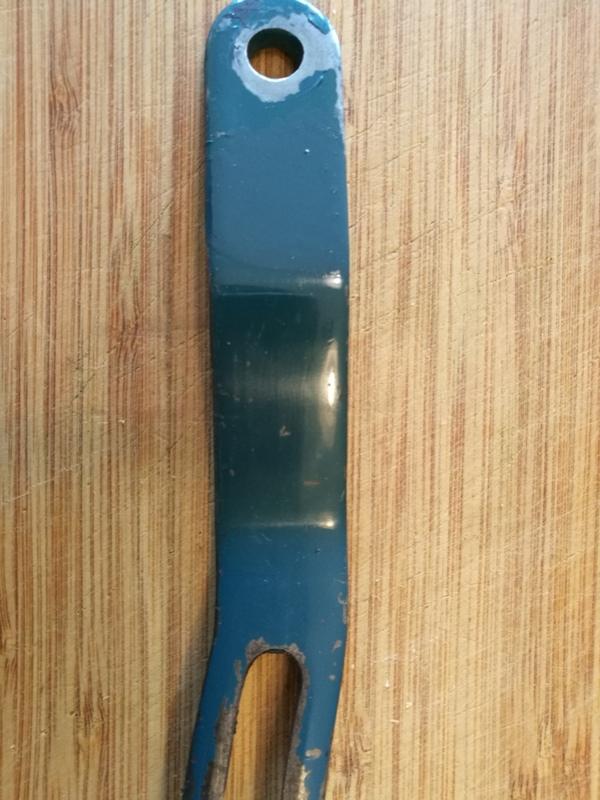
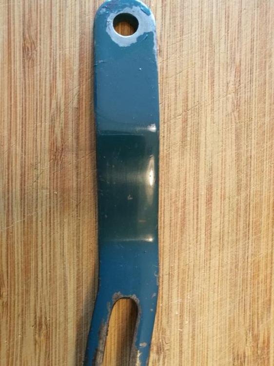
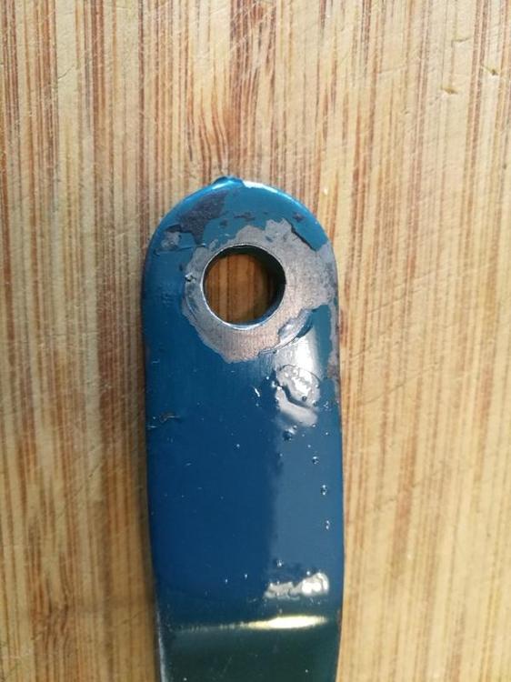
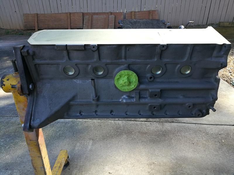
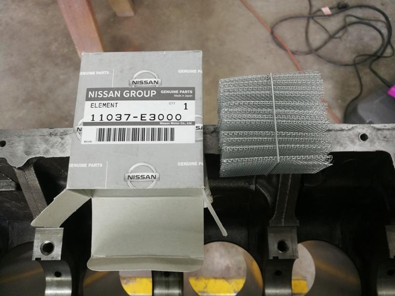
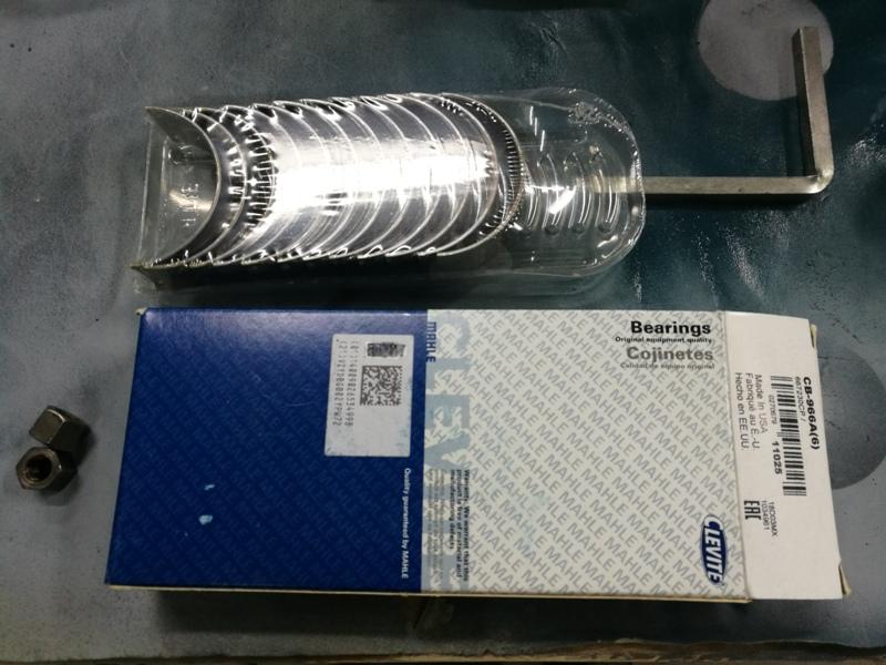
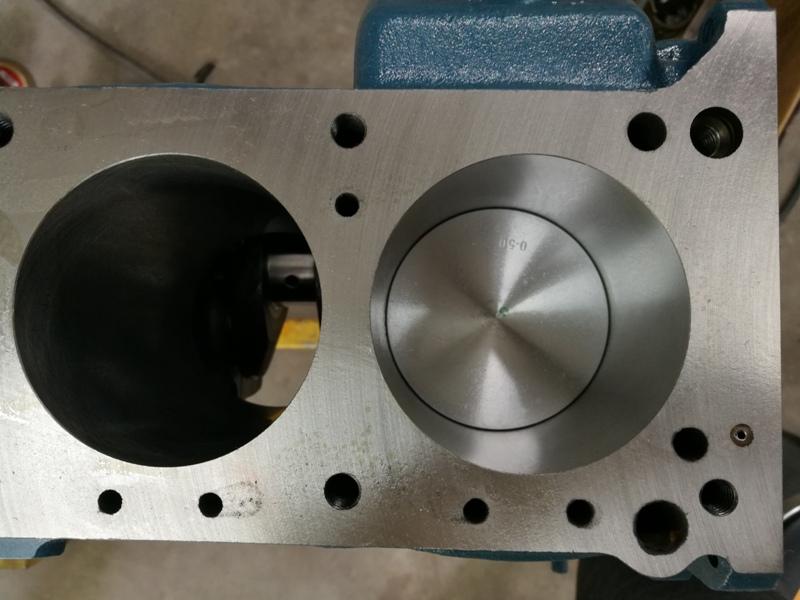
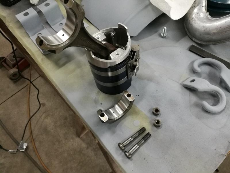
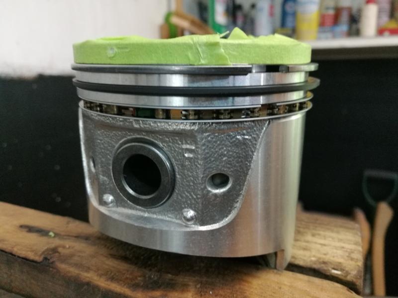
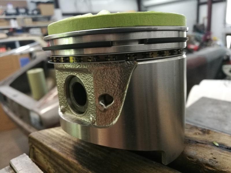
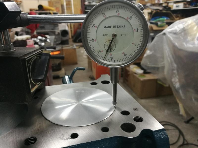
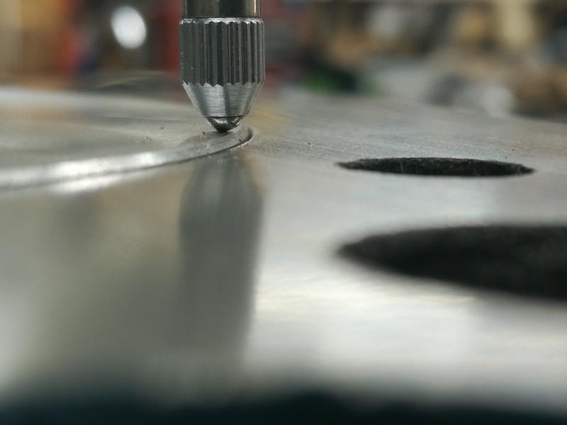
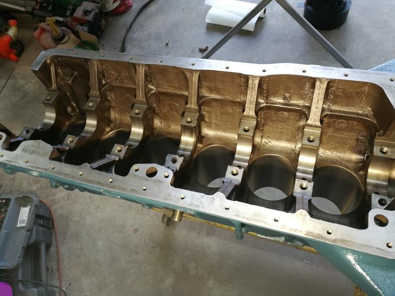
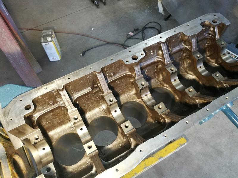
Next step on the engine block was to install the freeze plugs. I know some people paint the block first, but I wanted to do this like the factory. I do draw the line at fully assembling the engine and then spraying the blue/turquoise/green color with over spray landing on the head and oil pan though! For paint match, a few parts on the engine still had original paint. For example, the upper alternator bracket still had original paint on it. I was able to get that scanned at my local paint supplier and have them mix up some Nason enamel. Here are a few pics with the newly mixed up paint dabbed onto the part. I let the paint dry before taking the pics: I think it is a pretty good match, as I find it hard to see in the pics. I put it on the flat portion of the arm just below the bolt hole. You can see the raised up area in the third pic pretty well. Next, I masked up the blocks upper, front, and lower surfaces, and the oil filter location: After painting and letting it dry, I started assembly of the short block: After the crankshaft was installed, I put the rings on the pistons, and put the piston and rod assemblies in the block (Front and back of piston showing ring groove orientation): I used high quality masking tape to protect the pistons during ring installation. I had to be careful, as I do not own a ring expander. With the amount that was removed from the top deck, I was sure to measure the amount that the .030" ITM pistons extend up out of the deck. The reading is .025". This means gasket selection will likely need some special consideration. Instead of stock, I think I will need to go with a Cometic MLS... probably from Whitehead Performance as they have a listing of many sizes that I haven't seen elsewhere.


-
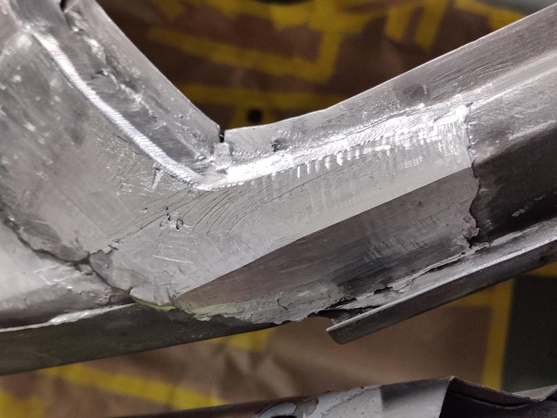
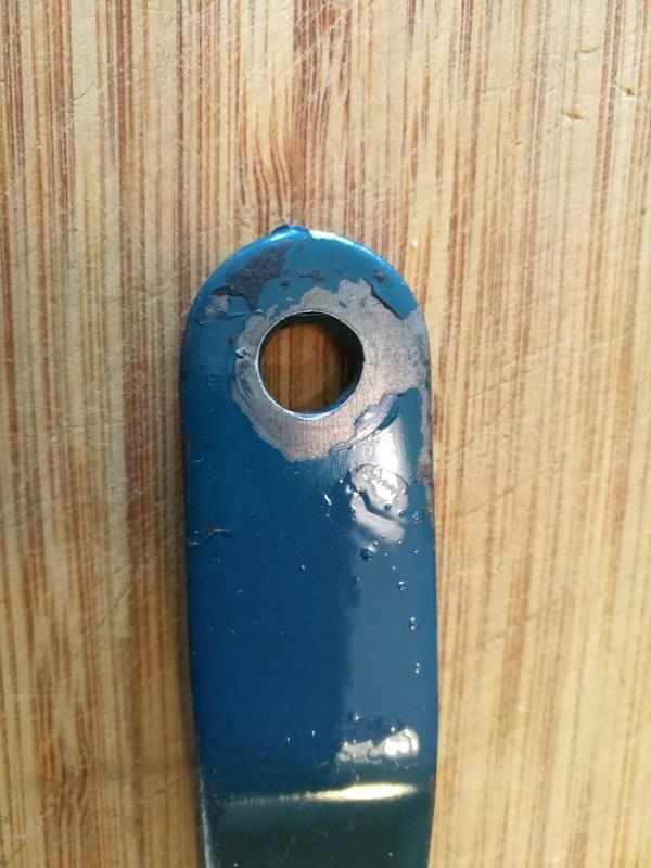
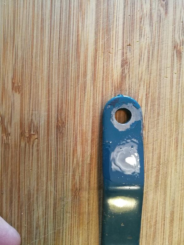
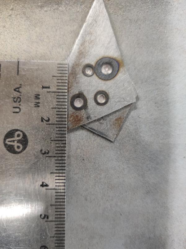
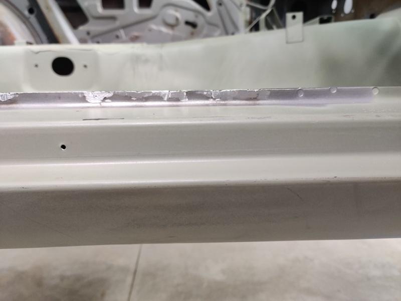
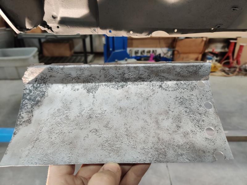
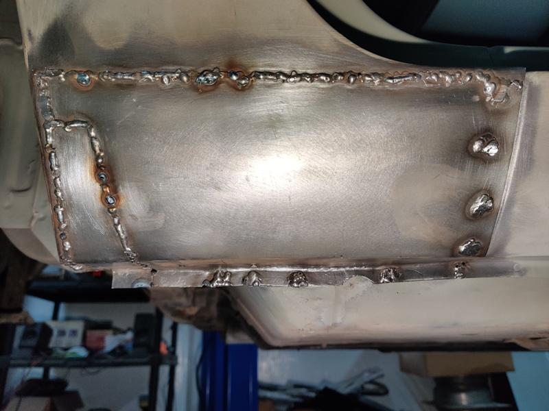
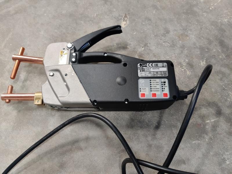
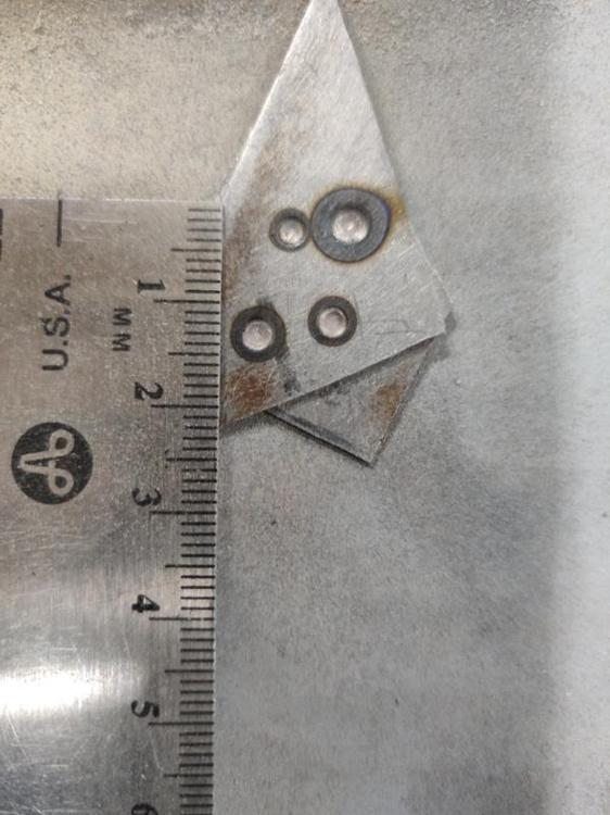
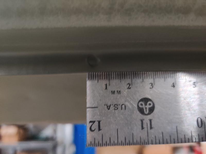
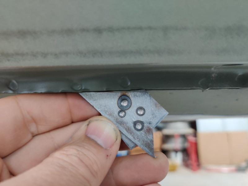
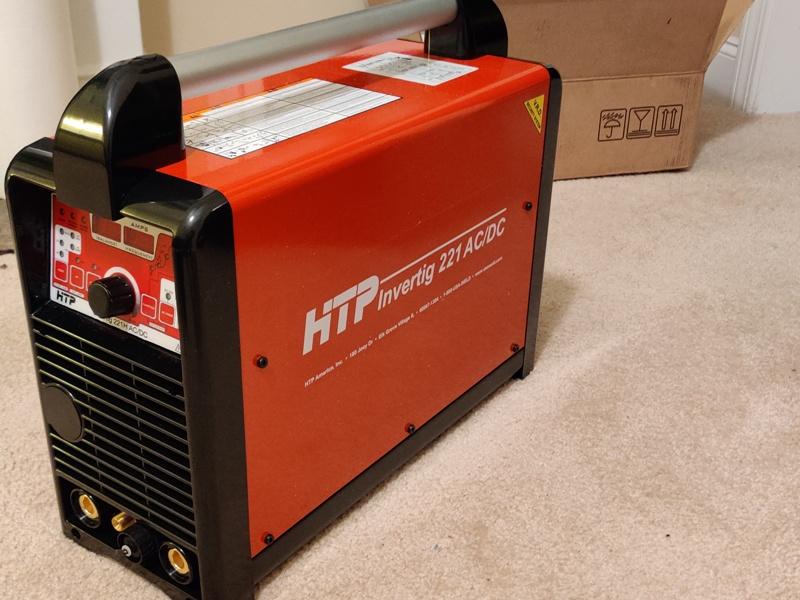
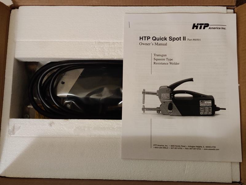
Hi, I bought a spot welder: a HTP Quick Spot II spot welder (along with a Tig welder) over the Black Friday time period (sale still going on now fyi) and was asked by someone reading my "bringatrailer" 240z build thread to share some information about it after I got it up and running. Well, here goes: Here is the spot welder. The special offer is currently $300 off on qualifying products when you buy the Tig welder. This spot welder counted as a qualifying product, so that is nice... It comes with the copper arms and tips you see in the pic. These are good to get you started with making spot welds in basic configurations. USAWeld sells other tip configurations if you need to spot weld different areas that these tips won't reach. There is a control panel which allows you to choose parameters for different welding situations. The settings from left to right in the picture below are basically "on/off pulse power" vs. "continuous" power, selection of thickness of metal being welded, and fine tuning of the duration of weld operation. There is also a pressure setting, which adjusts the amount of pressure the two contacts close upon the sheet metal with. The pulse operation can be used for high strength low alloy, galvanized, or weld thru primer coated metals according to the manual. It uses time between heat pulses to burn away contaminants for a better weld. Continuous can be used for clean metal. You follow the guidance in the manual and set the second setting based on the total thickness of the panels being welded. In the next pic (I only did one sample piece) the welds correspond to the following settings: Weld order from top left to right to bottom left to bottom right is: 1, 4, 3, 2: Weld 1: (top left): 175 lbs, continuous, 1 mm + 1 mm, and default duration Weld 2: (bottom right): 265 lbs, continuous, 1 mm + 1 mm, and default duration Weld 3: (bottom left): 265 lbs, continuous, 1 mm + 1 mm, and 1 step up from default duration Weld 4: (top right): 265 lbs, pulse welding, 1 mm + 1 mm, and maximum duration If it isn't apparent, you should notice that the size of the spot welds is quite small. That is, the diameter of the "divot" is much smaller than that of the factory spot welds on our Datsuns. Here is a reference image: The factory spot weld on the lower edge of this rocker of my 240z (apologies if it is hard to see) is about 5 mm in diameter. The largest of the example welds done above on the test piece is about 4 mm. Here is another reference photo: So, a ready made observation is that the HTP Quick Spot II isn't going to replicate the 240z's factory spot welds. However, it's kind of close... and if the performance is as good as shown in the video below, then maybe getting factory "performing" spot welds is a box that can be checked with this welder. And perhaps making them look factory is pretty easily done with a bit of creativity? I'll be exploring that coming up in the new year in my 240z build thread, if your interested in checking that out. Hope this helps someone. Garrett
-
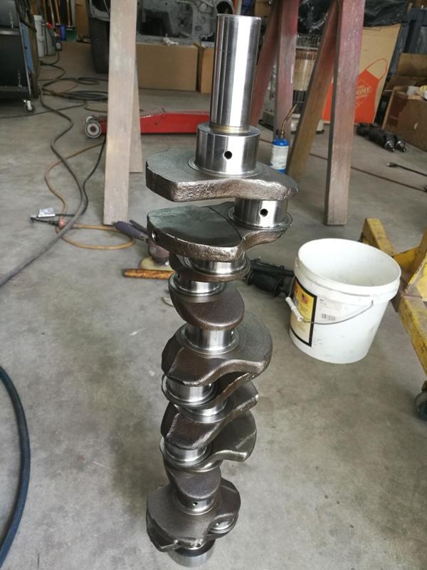
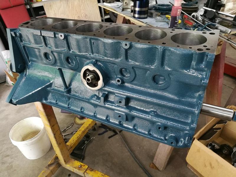
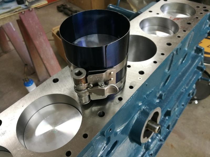
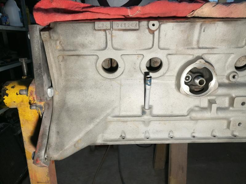
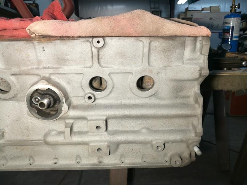
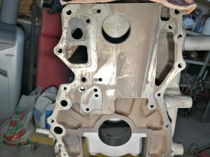
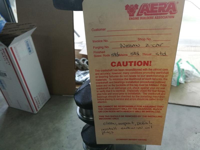
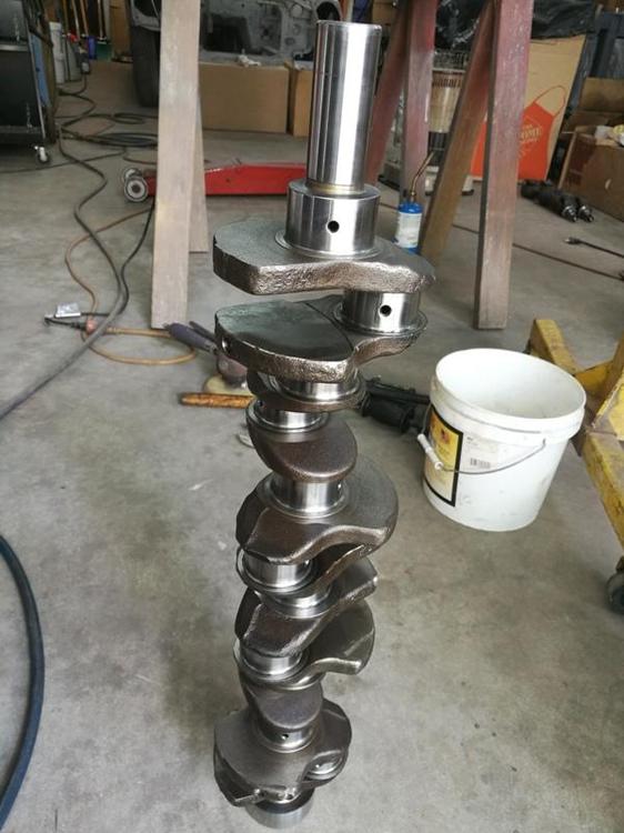
Got the spot welder working today. I will post some pics soon. In the meantime, thought I would change gears and put some engine related content the build thread. After the leak down and compression tests were complete, I started disassembly of the engine. Here is a 1 minute long video of the crankshaft condition before removing from the block showing the condition of the rod journals. The engine most likely has 130k miles on it, if I recall the odometer value correctly (and if the odometer hasn't spun over twice!). Also, I took another video showing the crank rotating in the block before removal. Always nice when the crank rotates this freely, an indication that the block is as straight as it was when it left the factory. The cam rotated very easily in the cylinder head also indicating the head is straight, not warped or bowed. The block was dropped off at Will's Auto Machine Shop, Inc in Chamblee, GA. They've done a lot of Z car stuff over the years and know there way around the L-series. I dropped off the .030" oversize ITM pistons, the crank and rods. They bored the block and honed for the pistons, polished the crank, (still standard on rods and mains), cut the deck to clean things up, installed the pistons in the rods, and sized the piston rings. Here are some pics of the block. I used the sand blaster to get in between the bores and clean out loose rust and corrosion. There was a substantial amount of sediment in the block when I first took it apart. I suspect the previous owners didn't protect the cooling system as well as they could have with the appropriate amount of anti-freeze. I cleaned the inside of the block with a brass wire brush (after the hot tanking done by Will's Auto Machine) Here is the prepped crank and one of the piston and rod assemblies:

-
Sure. I've got to sort out the electrical hook up for it and the Tig welder in the garage, so it may take a week or so. I will do a separate thread when I do the testing. I will cover the job in detail in the build thread later as well.
-
Bought a couple of toys to use on the restoration... and other car projects! Tig welder: Spot welder: usaweld.com is running a promo right now. The spot welder counted as qualifying products for discount ($300 off), and I got free shipping. The tig welder that I got is the 220 volt version and not water cooled. Should be a lot of fun to learn how to use it well. I've got an aluminum radiator for my other Z (highly modified) that needs some brackets welded onto it and some other welding jobs in line for that car as well. I'm also interested to see how well the spot welder does on the rocker panel repair for the restoration Z.
-
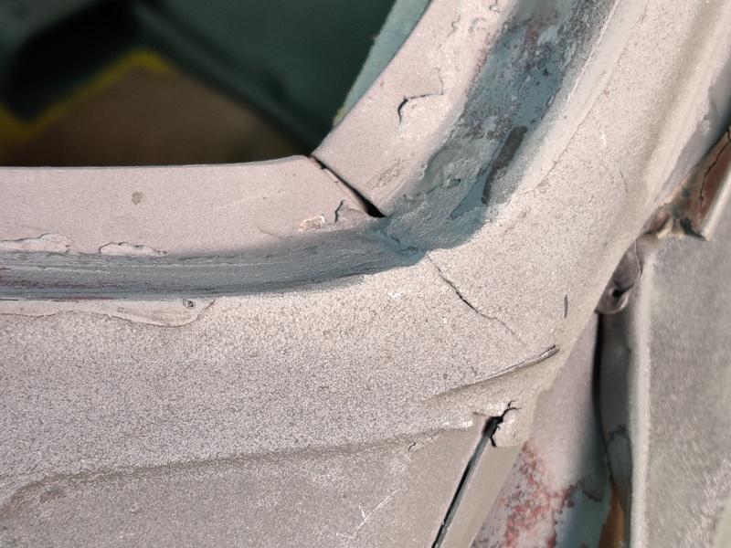
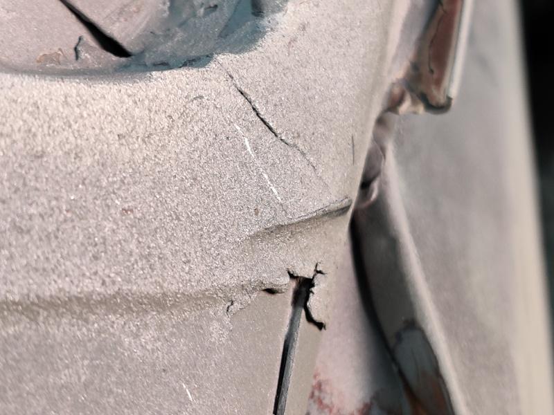
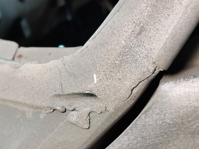
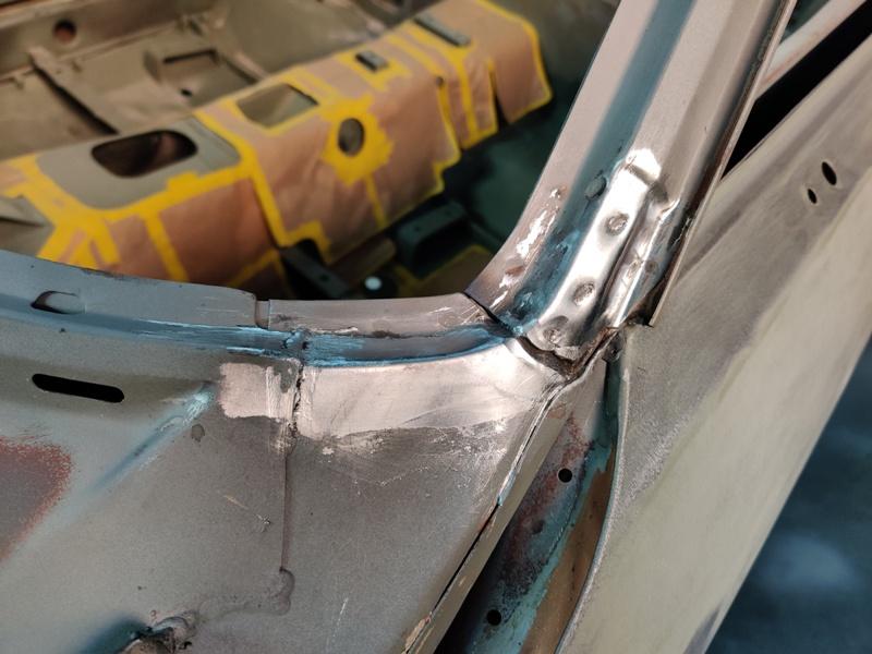
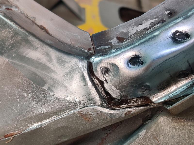
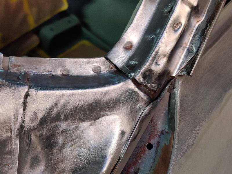
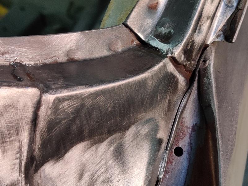
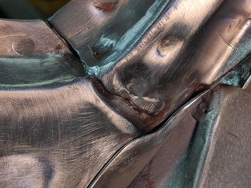
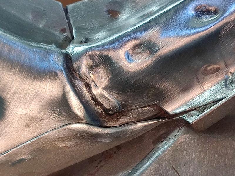
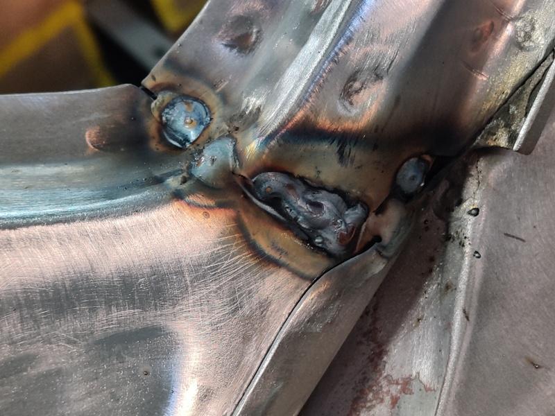
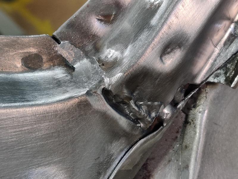
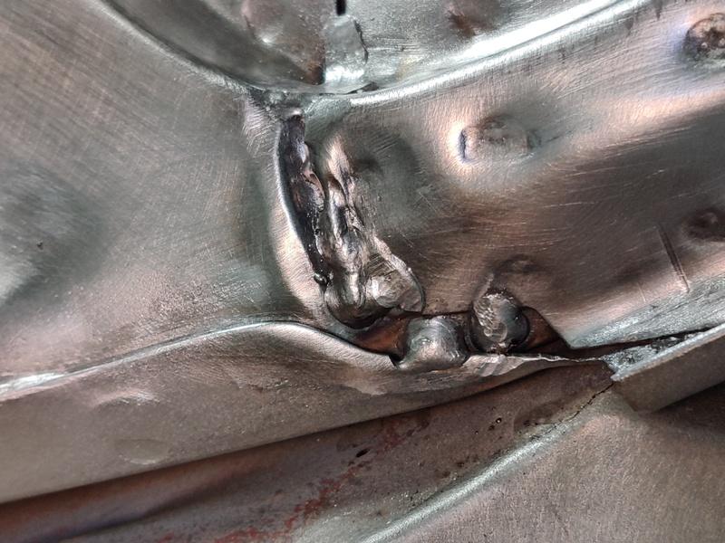
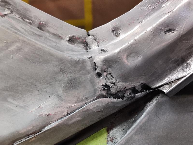
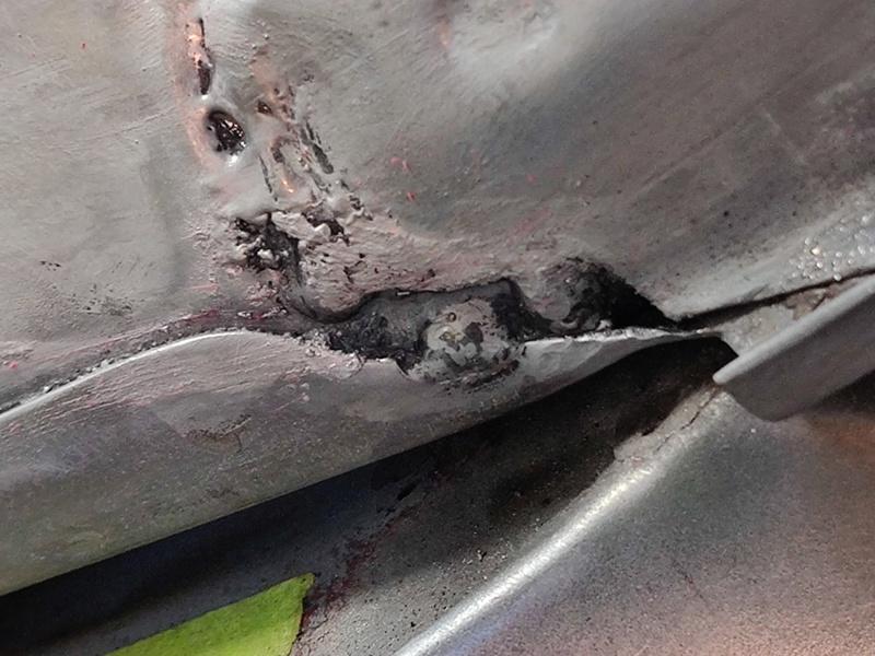
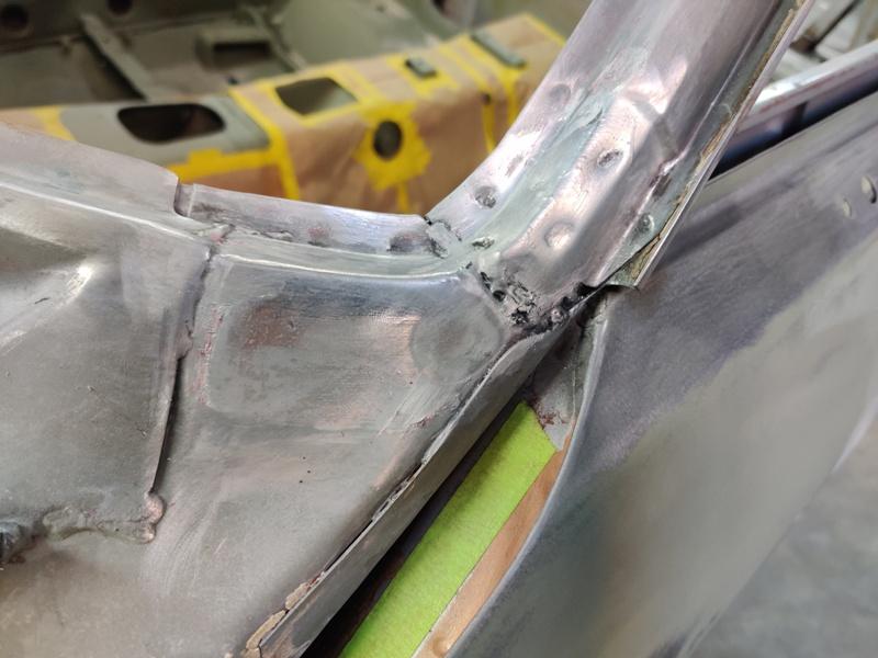
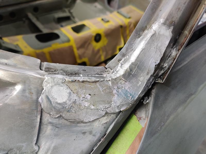
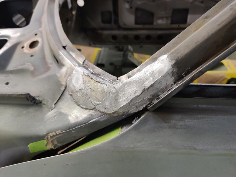
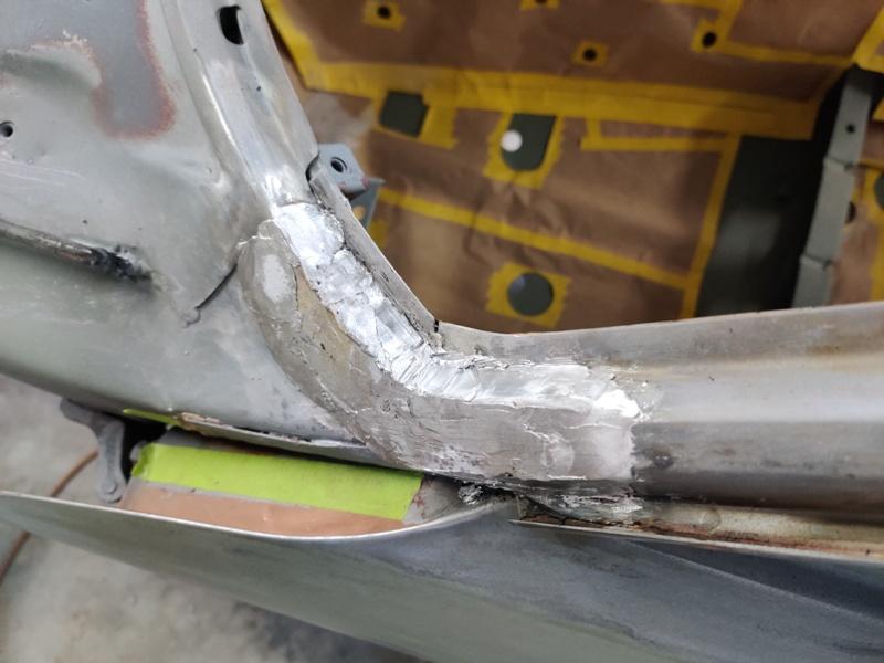
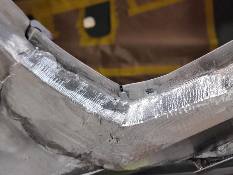
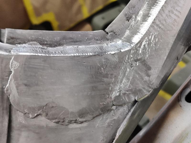
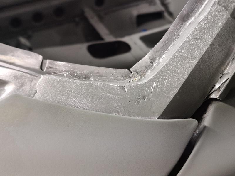
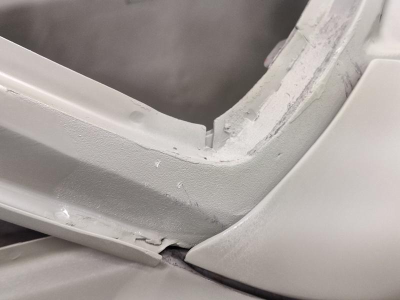
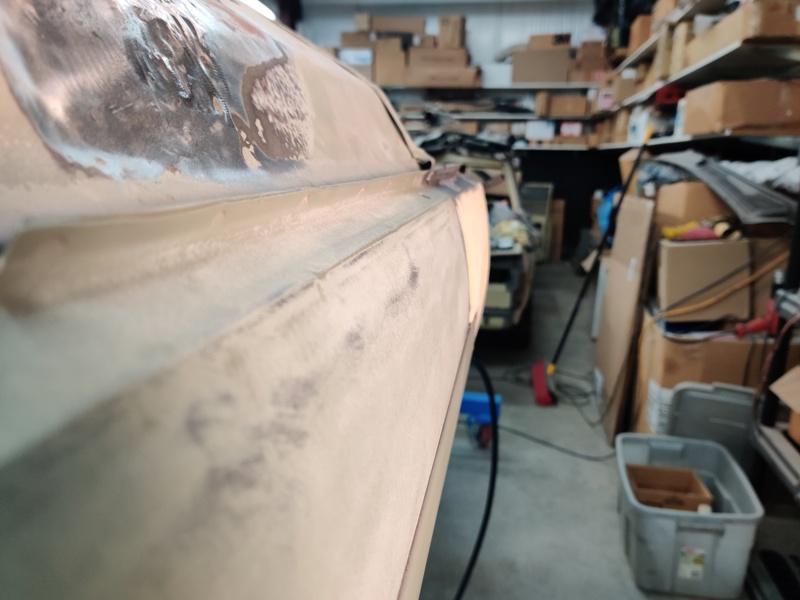
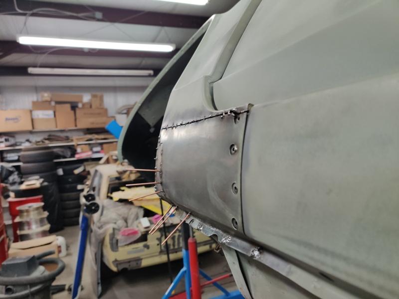
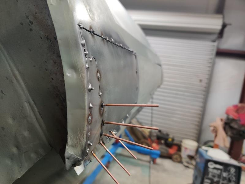
Next up to share is a repair to the A pillar where it attaches to the unibody. Evidently there was some flexing going on here at some point. Looking at the unwelded seam (inside edge of the corner), it seems obvious why this happened. Pics show that aligns with the crack in the lead body filler: Also, note the indentation/impression made by the back edge of the fender. Is that how it came from the factory, or is that unusual. The driver side fender did have slight accident damage just behind the wheel well opening, above the body line. Maybe a slight side impact there caused the back edge of the fender to bump the lead? I used a propane torch to heat the old lead and watch it run off onto the floor. Then I used a blue stripping wheel to clean up the surface of the metal, followed by liberal use of the torch and compressed air to blow the old lead out of the crevices... followed by use of a stainless wire brush. Given the lack of welds here, I strategically set a couple of tacks and a bead with my MIG welder for good measure and ground the ones in the inside corner down flush: Next came the tinning. I watched a Youtube video to get a reminder of how to tin. An Eastwood lead kit from my restoration of my other Z back in 1993 was put back into action. The tinning "butter" did pretty well considering it was 26 years old. At least, I think it did... I neutralized the acid with some water and baking soda mixed together. Then went over the area with a wire brush. Next came the lead filler. Again, I used a standard propane torch: I think it came out pretty well. Next, I started shaping with a file as well as a die grinder: More filing and some sanding with a DA and 80 grit. Looking closely at the passenger side (3rd pic), I see that the body line is altered before it meets the back edge of the fender. I will replicate for the driver's side.