inline6
 Subscriber
-
Joined
-
Last visited
Everything posted by inline6
-
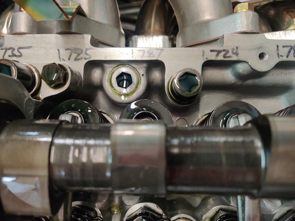
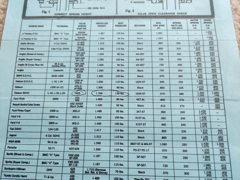
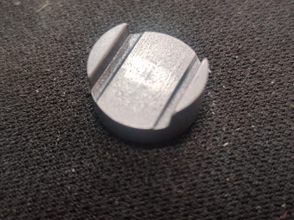
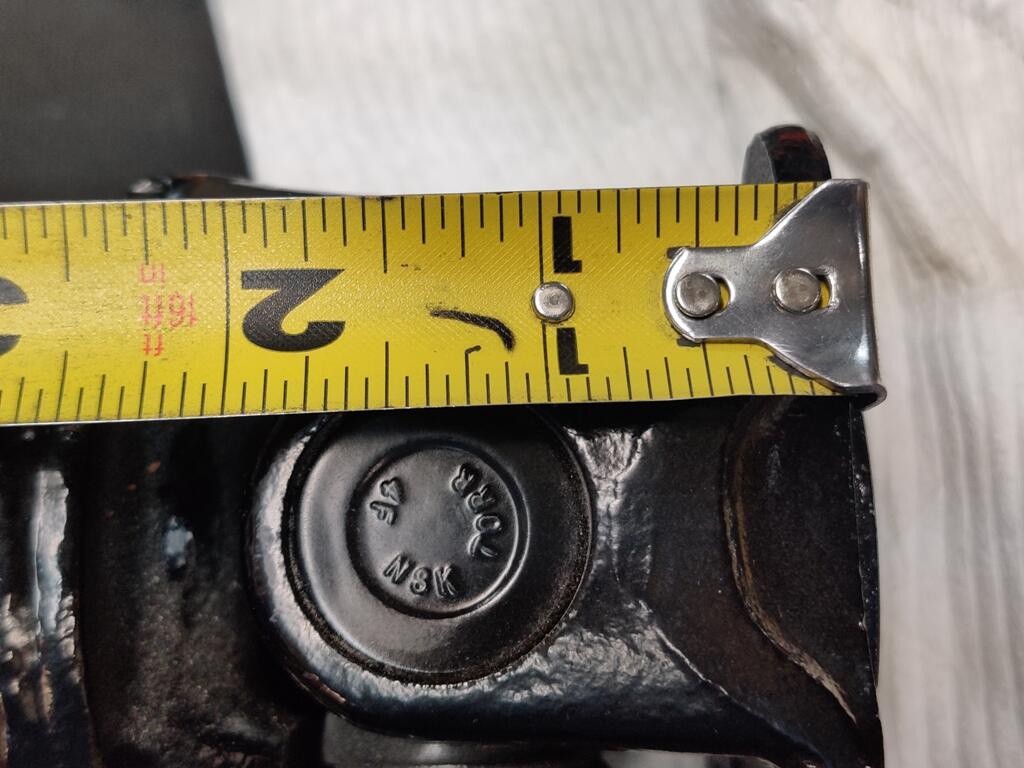
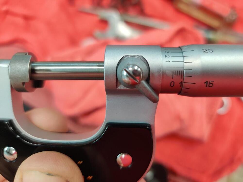
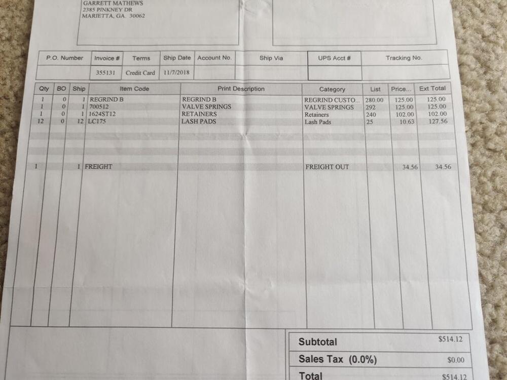
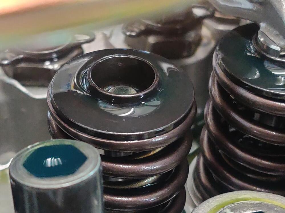
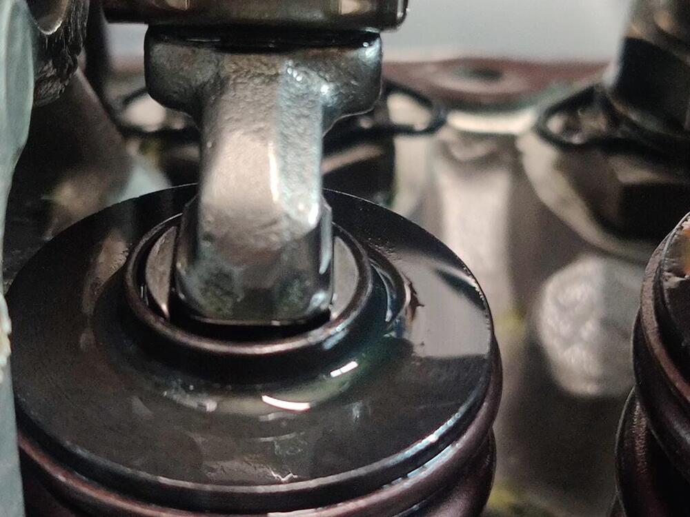
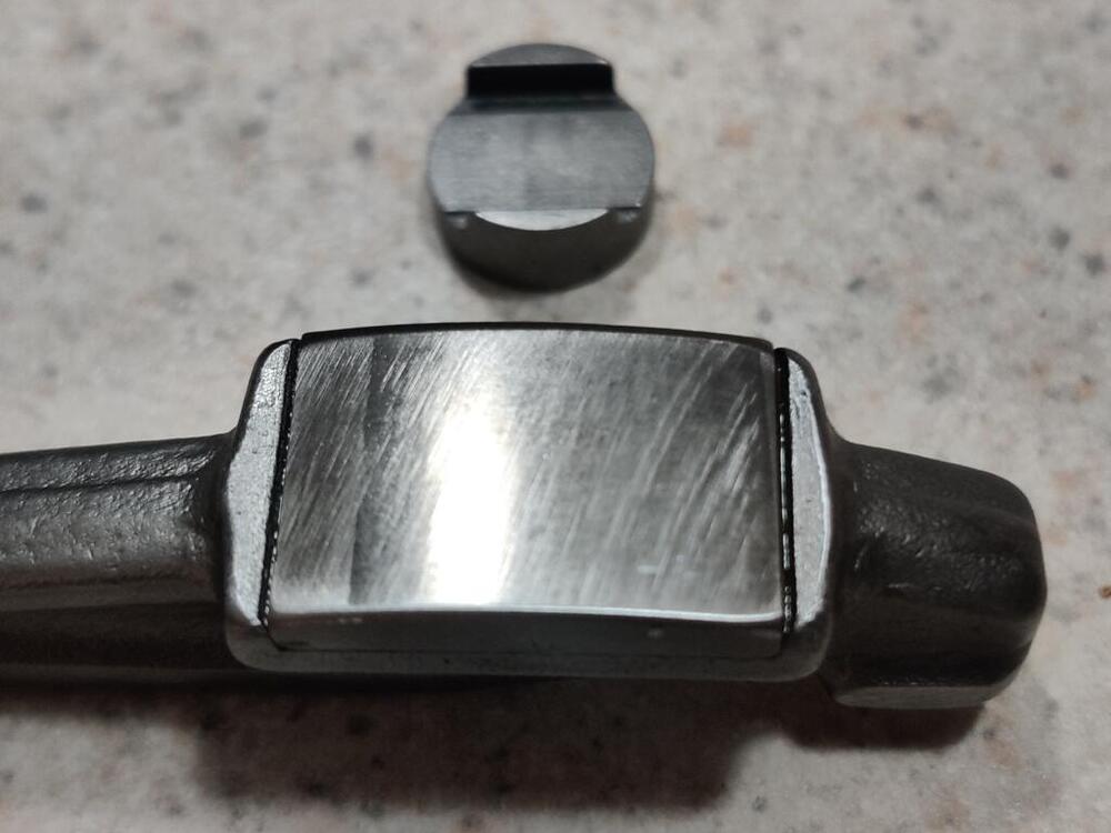
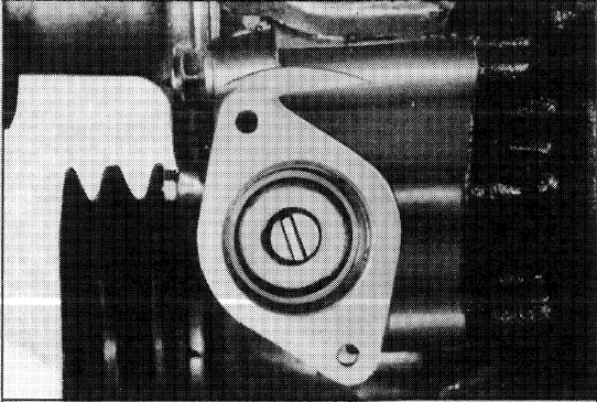
 Yeah, something really isn't right. I have snapped a bunch of pictures and talked with my engine builder, who did the work on this head. The current hypothesis is that the SI Stainless valves I bought are too long. The installed heights are still visible in black marker on the cyl. head: 1.787" is a lot more than the specification paperwork from Iskenderian (1.700"): The lash cap I pulled out with the one rocker arm I removed last night is .117" and about 3 tenths. Stock is .118". But the "kit" I ordered from Iskenderian has .175" lash pads, (part LC175 - is .175" thick - I looked it up on their site): The retainers currently installed look like the Isky ones. The depth to accommodate the lash pad is notable. Comparing to another exhaust valve which has not had the rocker and lash pad removed, the lash pad (I am assuming also .118"/stock) is "buried" in the retainer. So, the theory right now is that SI Stainless valves are taller than the stock valves (4.620"). I think I will have to pull the head. My engine builder is a great guy and he has provided me with so much value over the years. In this instance, I should have checked the wipe pattern before installed the head, but I did not. As far as I can tell, no damage has been done. So, I think I have been fortunate here.


-
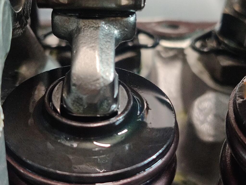
This evening, I examined the needle and seat from the rear carburetor. If found some residue on needle. When I used a wire brush to clean it up and examined the needle (it is metal) closely, I could see a light wear ring. I found two spares I have had for decades and examined them. The needle portion appears to be made out of a hard rubber. I may have bought them new to swap out in my carbs that I used to run on my track car, but never did. Can't remember now. Anyway, they looked pretty much like they were unused. So, I swapped those into the front and rear carbs and reset the float levels using the "wet method". By siting the fuel in a clear tube, they are both set perfectly now. After that, disengaged the balance screw, and set each carb throttle adjusting screw so that I saw the lever move. I set each at about 2 turns in. Then, I turned the key and the engine came to life. Within a couple of minutes, I had the front and rear carbs running on just the carburetor throttle adjusting screws. I turned in the auxiliary shaft adjusting screw to operate the linkage and then adjusted the balance screw to get the air flow the same between the carbs. At that point, I was going check the timing and start adjusting idle speed, but the clatter from the valves was too much and I began to be concerned. So, I decided to shut it off and pull the valve cover. Upon doing so, I was pleased to see no obvious damage to the cam lobes (I had a couple of bad experiences with new cams in my track car). I started checking valve clearances. Just about every one of them did not have enough clearance. I went through and made minor adjustments until - you know it... the last one. For that one, I ran the 14 mm adjustment screw all the way down, but I ran out of adjustment and still couldn't get a .20 mm feeler gauge (it is an intake valve) in between the cam base circle and the rocker pad. So, I pulled the rocker and lash pad. The wipe pattern is not centered and nearly off the front edge. Guess who is going to have to pull all the rockers and potentially change out some lash pads?
-
Hahaha - you guys got me laughing. And good advice, I didn't even think about using water - because everything is new and done right, right? Wrong! Dang water pump. Anyway, I just got in from the garage. I finished my to do list. I did the thing with pulling the oil pump and using a dummy shaft and a drill to pump the oil through the engine. I hate the part where you have to remove the oil pump again and reinstall the distributor drive shaft. I made a big oily mess. But, the engine has been sitting for years after being rebuilt, so I feel better pushing oil through it before cranking it. I didn't want to spin the engine with the starter as long as it take for the oil pressure gauge needle to show pressure without pumping oil everywhere first. After that, I pulled the spark plugs and switched on the starter. I kept it spinning until I saw the oil gauge needle just move a bit. It is amazing how long that can take. I didn't time it, but I bet the starter was engaged for 30+ seconds. After that, I put the spark plugs in, hooked up the leads, looked at the engine bay for about 10 seconds trying to think of anything I had missed for the 30th time today, and then thought "f*** it, let's go". I lifted up each carburetor piston and shot some starter fluid in the direction of the intake. And then I turned the key. I got a bit of life from the engine within a couple of cranks, but when I let the key go it would die. I tried that a couple more times and got the same result. Having a good amount of experience with these carbs, the symptom seemed to be that the two carbs were way out of balance. I operated the main linkage and looked at the resulting movement at each carb linkage. The rear carb linkage was activating, but the front carb linkage was not. I adjusted the screws to get them both moving when I threaded in the main throttle screw. Then I tried again. This time I used the starter cable. It fired up, but having fresh in my mind what @siteunseen had said, I treated the ignition keys like a feather trigger, and when the engine revved up pretty high, I turned it off. I pushed the starters in a bit and tried again. This time it fired up and was holding revs at about 2400. Oil pressure was showing 90 psi (I assume the sender I bought must be the one for the early cars?) Not pausing a second, I swung around from behind the dash to the engine bay and bounced my gaze around to check on key things. Almost immediately I noticed fuel flowing up and out of the air vent in the top of the rear carburetor. So, I shut it down. I am not sure what happened there. I set the float levels just a few days ago. Perhaps I have a bad needle/seat. Total run time was only about 30 seconds or so. I was really hoping to run it for about 20 minutes at 2000, as the cam is new and the rockers have been reground. Really hoping that everything got lubricated enough quickly to avoid any problems. I will need to see what is up with the rear carb and try again.
-
Thanks for the advice. Unfortunately, I put coolant in before seeing it... And, I found out that the water pump (one of the few parts that I did not replace) was weeping coolant. GEEEZ! Thankfully, I have another water pump from a spare engine that seems like it doesn't have many miles on it. So, I had to drain the coolant and replace the water pump with that one, which set me back time-wise. I am taking a break now for dinner. But, I may try to start it after. Add coolant Complete electrical hook up of the Pertronix unit at the coil Install fuel hose on the fuel return line of the fuel rail Repair oil pressure sender wire/connector Remove oil pump and prime engine with oil (using drill and custom made shaft to drive oil pump) Add SAE 20 oil to the carburetors Check torque on cam sprocket bolt Check torque on crankshaft pully bolt Heat engine oil in the pan Install valve cover Add two more gallons of fuel Only a few things left...
-
I think today is "start up day". I have a rather short list of items to complete before I turn the key and see what happens: Add coolant Complete electrical hook up of the Pertronix unit at the coil Install fuel hose on the fuel return line of the fuel rail Repair oil pressure sender wire/connector Remove oil pump and prime engine with oil (using drill and custom made shaft to drive oil pump) Add SAE 20 oil to the carburetors Check torque on cam sprocket bolt Check torque on crankshaft pully bolt Heat engine oil in the pan Install valve cover Add two more gallons of fuel
-
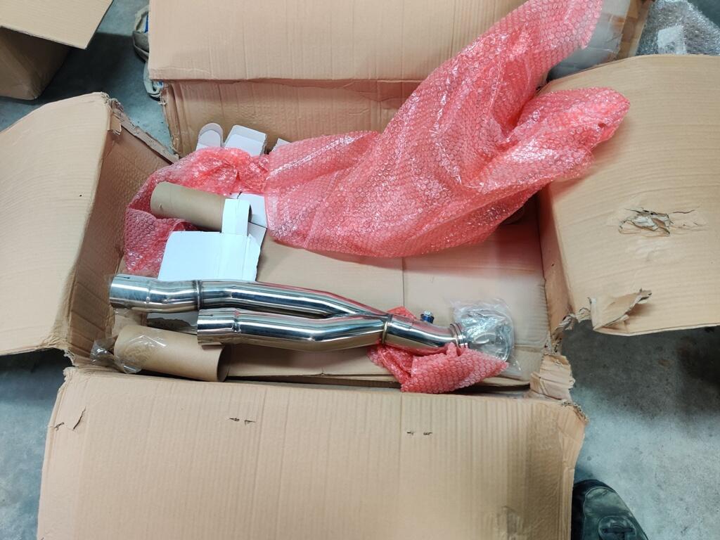
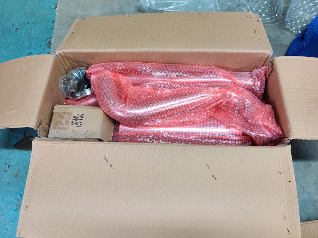
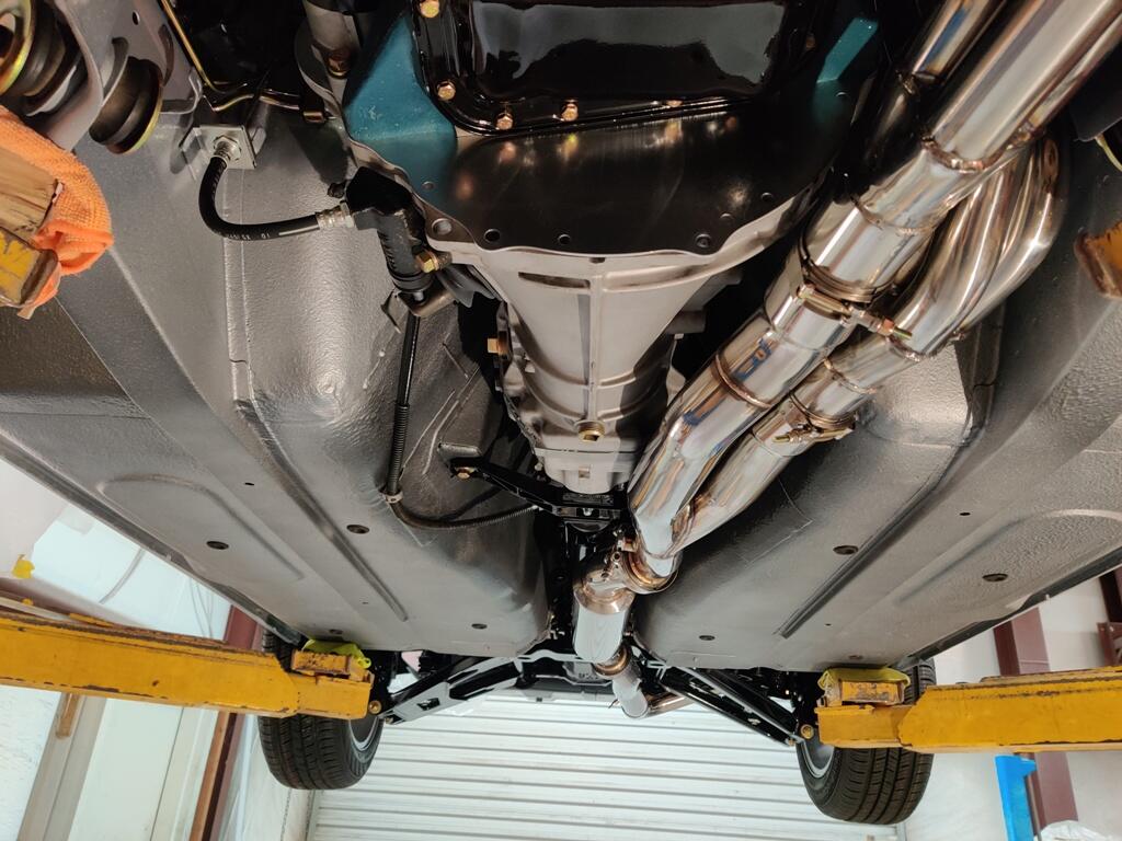
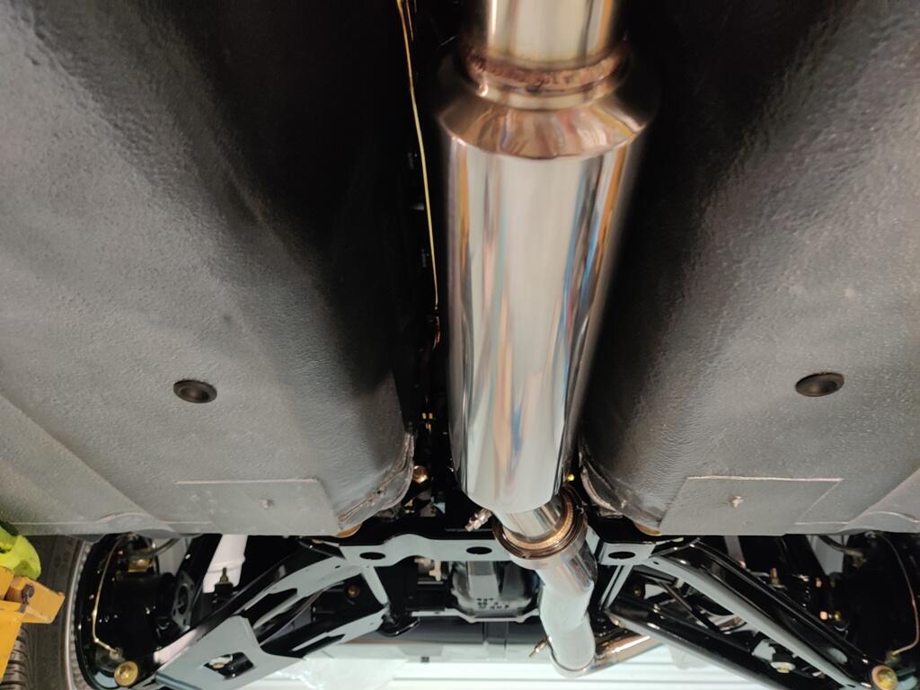
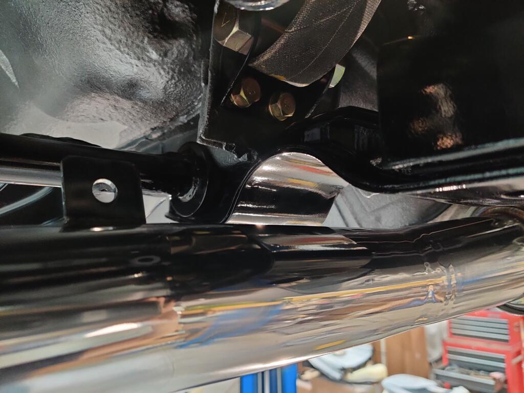
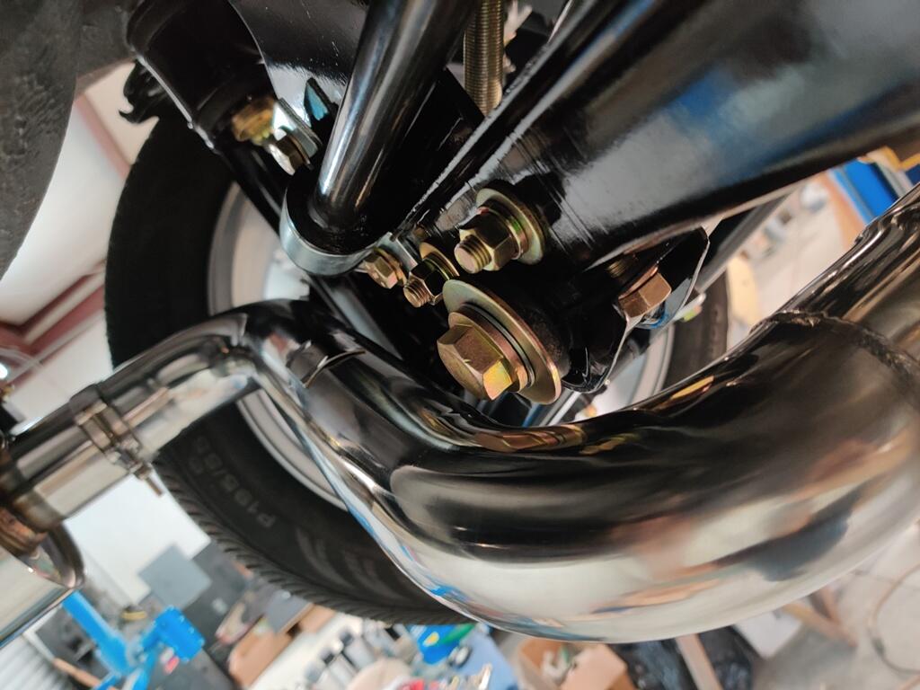
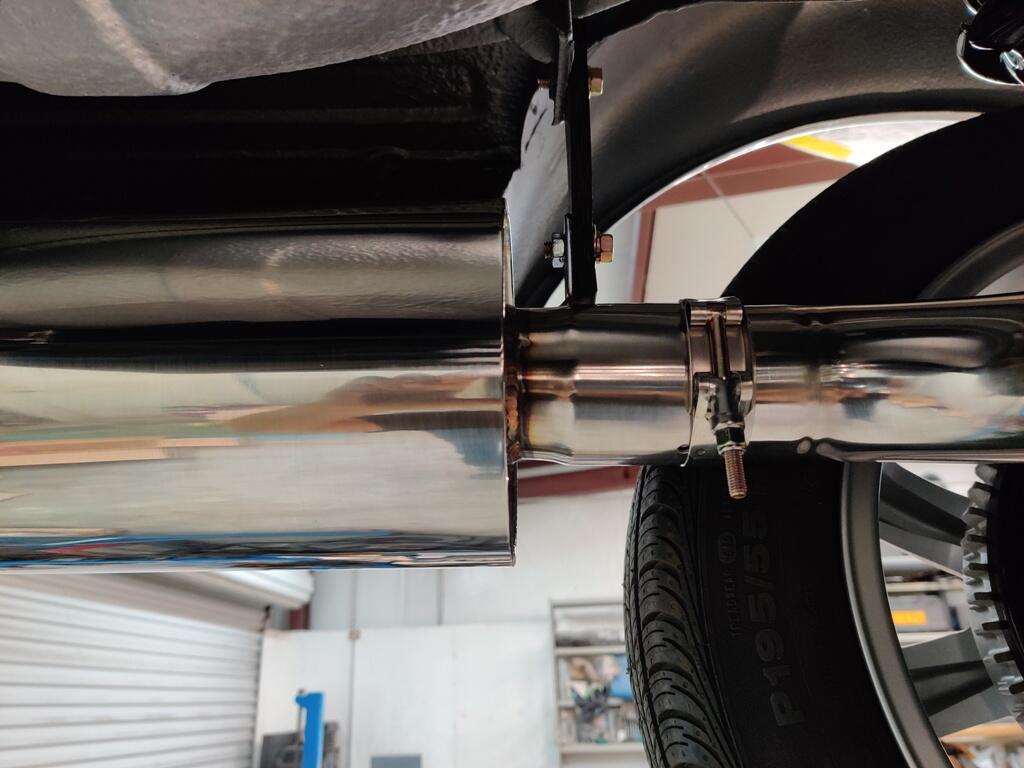
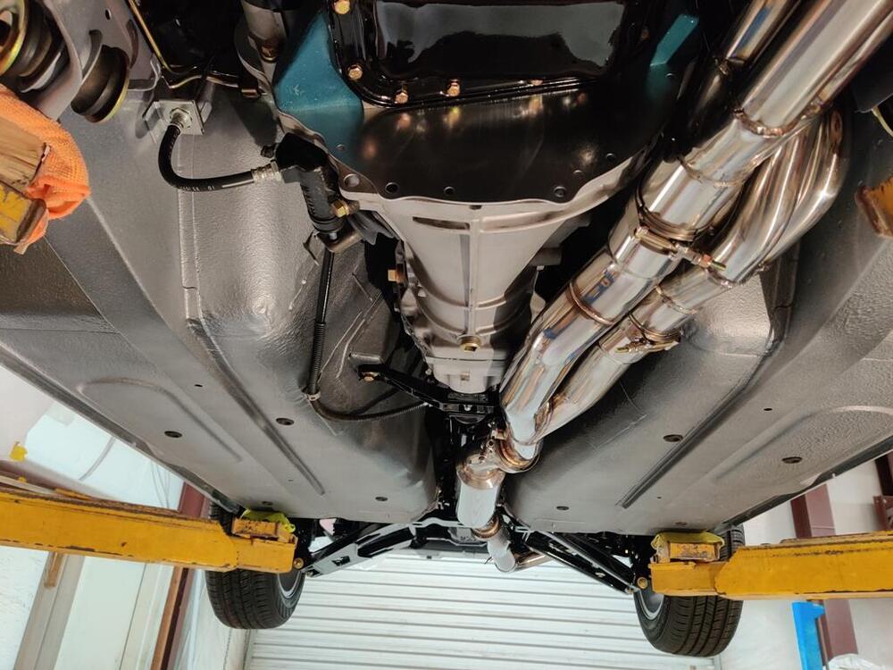
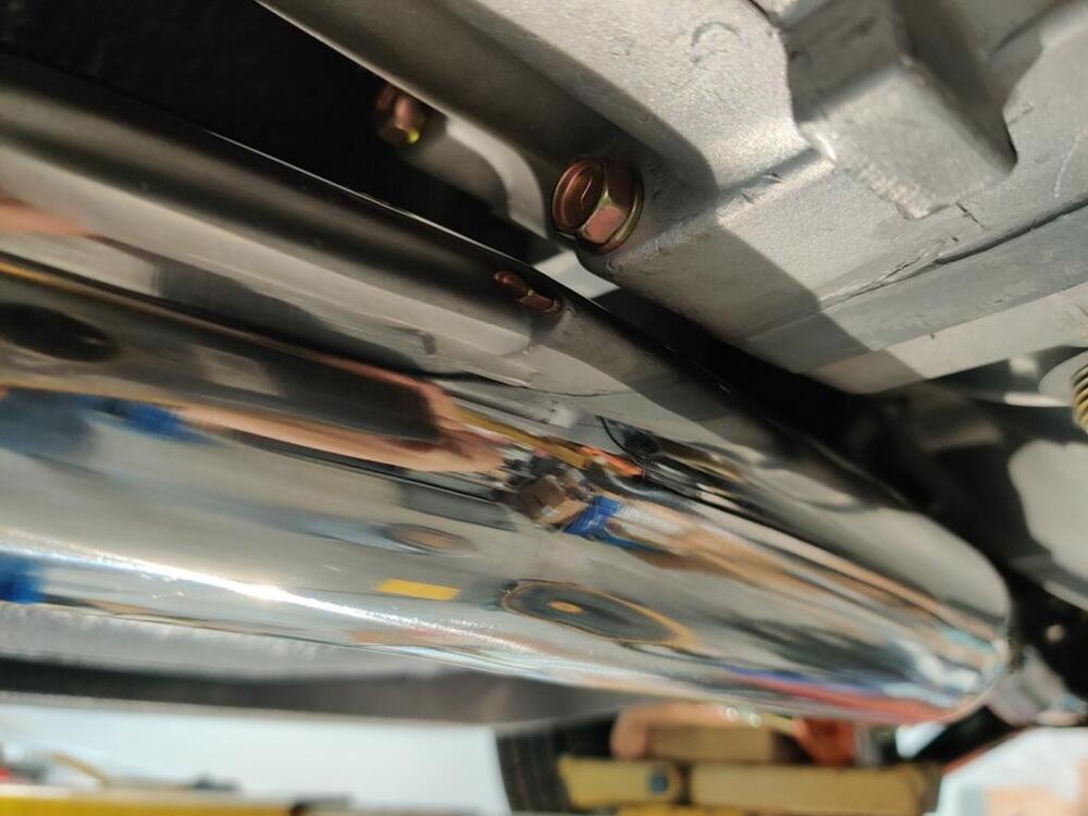
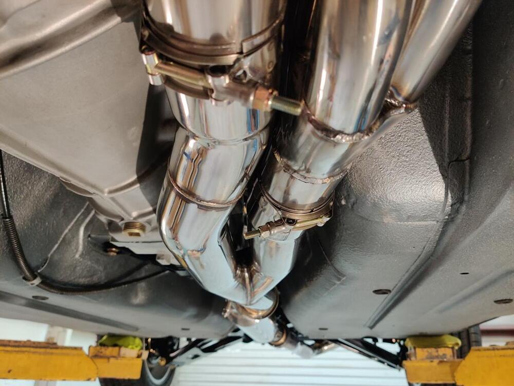
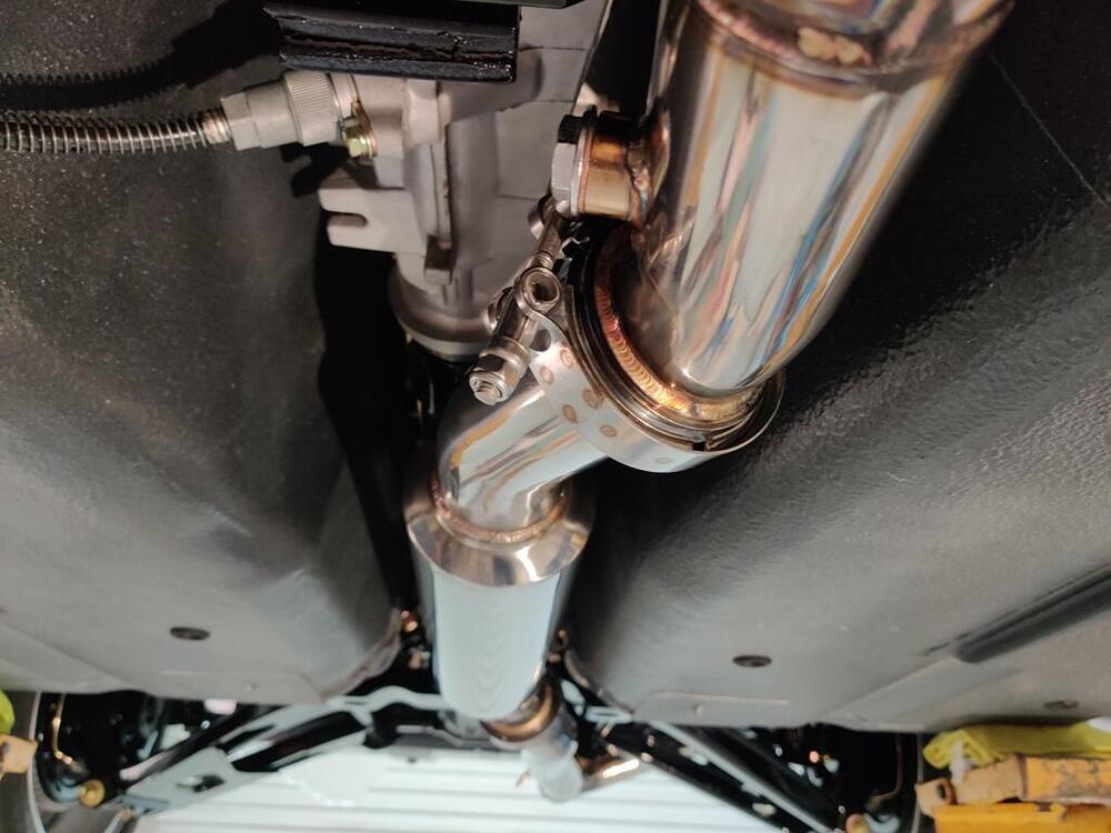
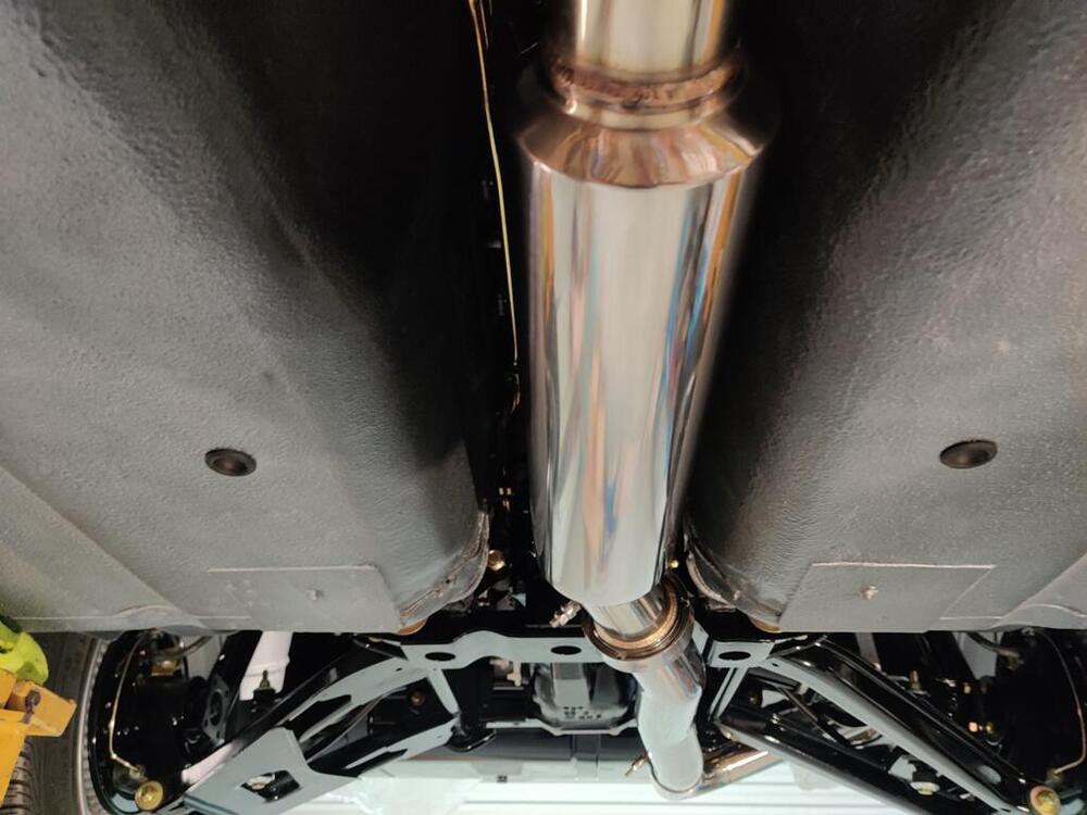
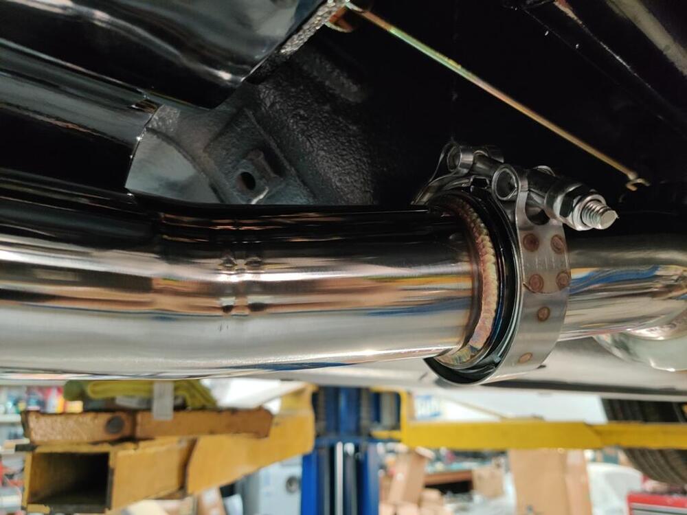
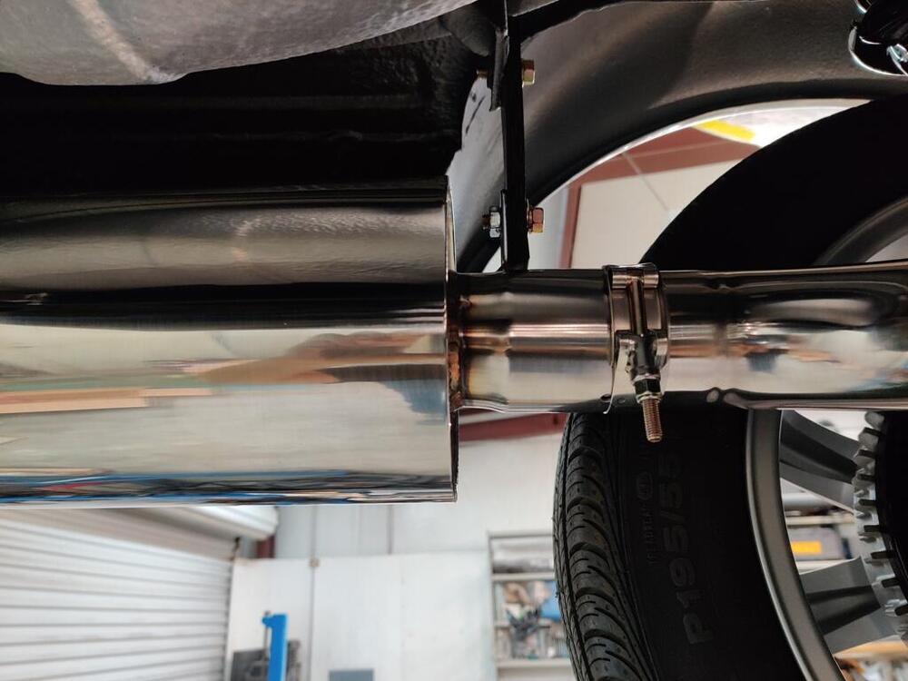
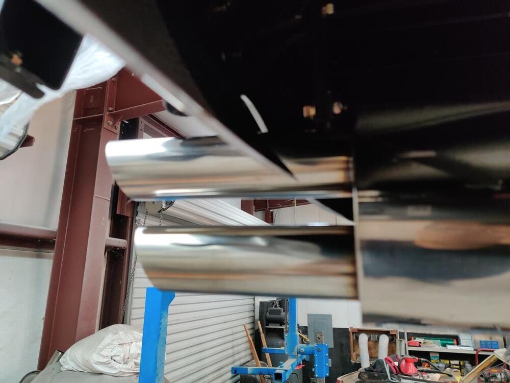
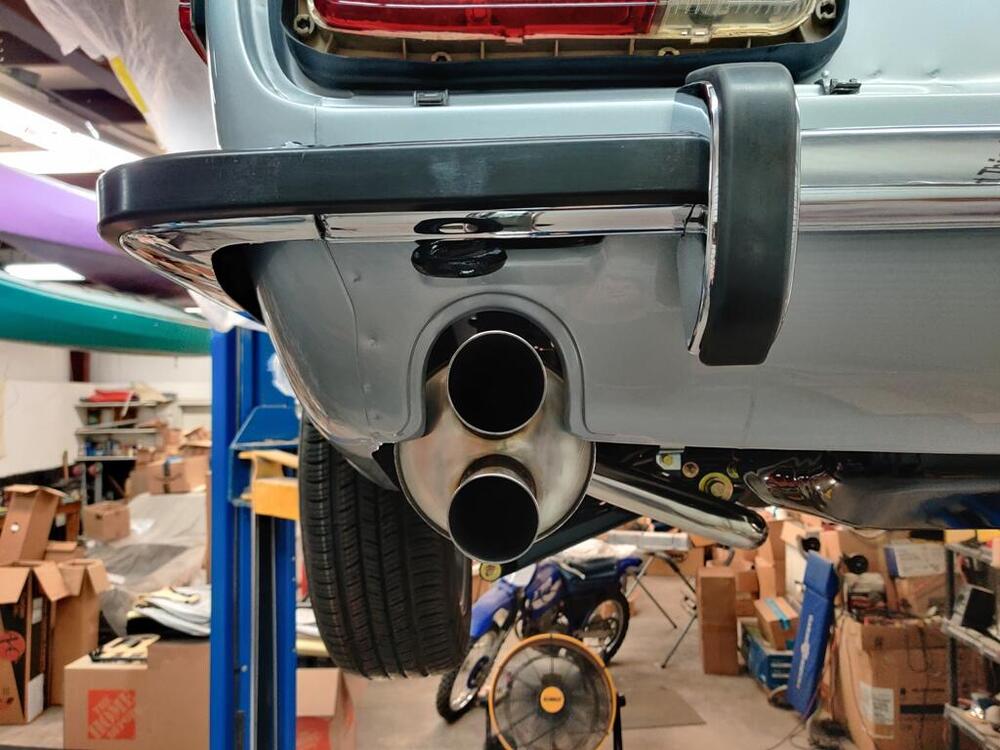
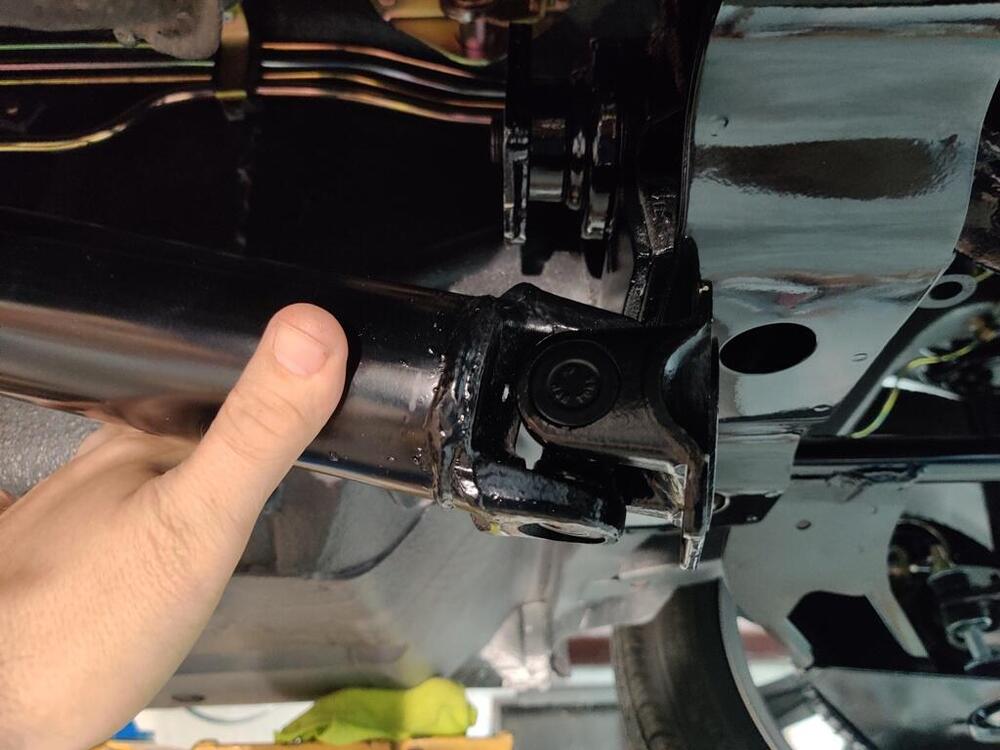
The driveshaft was delivered to me by FedEx today. During attempted installation, I found that I had to remove some of the original shield. I did this manually with a hacksaw, removing a linear inch of the shield. I measured and ran a piece of tape around the shield to mark where to cut. The remainder of the shield is of a slightly smaller diameter than the shield that is pressed into the tail section of the 240SX transmission. So, it slides within that shield, but with a small air gap. Assuming they removed 2 inches as I specified, I am kind of surprised at how tight the fit is. With the driveshaft installed, the front portion of the shaft (with the spines) is deeply seated inside the transmission. I will add a pic, but essentially, another 1/2 removed from the shaft would have been better. I don't understand why all the references I have found online for shortening the stock driveshaft for 240SX transmission conversion don't seem to match my situation. I confirmed I had the short (early) driveshaft. But instead of shortening by 2 inches (what I found others have done and as I asked for), I think 2.5 inches would be better. With the driveshaft in the car, I moved on to installing the Z-Story exhaust. The header was already installed, of course. So, I unboxed the rest of the parts and put them on the car. I found the fitment to be very good. There is one spot where the exhaust comes within 1/4 inch of the transmission case. However, clearance seems to be enough everywhere - I do not think there will be any rubbing. I also filled the transmission with Redline 75W90 GL4. There is a small list of things that have to be done before I can start the engine.


-
I am nearly certain that your engine's cam timing or (as well as possibly, and) distributor drive are incorrect. You need to confirm correct positions on all those things before messing with mixture of the carbs.
-
From where they are now, what is the total count to all the way up? For example, if 2 down made it drivable, then how many turns up until it stops? 3? 3.5? More?
-
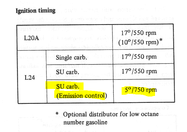
I just became intrigued enough to read this thread from the beginning. My post about accuracy of the distributor connection angle now seems silly to me given that you haven't been successful in getting the car drivable. My apologies. I know it could be many different things, fuel or electrical, but firing back through the intakes and running like complete crap tells me it is timing related. While you have gone through the steps to verify cam timing, I don't see that you actually confirmed it was all set properly all at one time. I think you need to do this again: Find top dead center of piston #1 (at the end of the compression stroke - cam lobes for cyl. #1 pointing upward as in your prior pic). With the crankshaft in the proper position (#1 piston at top dead center at the end of the compression stroke), verify that the "correct" mark on the crankshaft pully is in "perfect alignment" with the pointer on the engine front cover. If I remember correctly, the "correct" mark (0 degrees) is the one on the far right when standing at the front of the car and looking down onto the pully marks. With the crankshaft in the proper position, verify the 'dash' mark on the cam gear and "v" on the cam plate are in the "correct" positions. Reference page EM-25 in the factory workshop manual With the crankshaft in the proper position, verify the oil pump/distributor drive gear "tang" alignment is "correct". Reference page EM-32 in the factory workshop manual: With those things have all been verified, then you know the cam timing is not "off", and the crankshaft damper is not "off" and the distributor drive is not "off". At that point, you can check ignition timing properly. The correct initial timing specification is dependent on which distributor you have. From the factory workshop manual - if I am not mistaken, US cars were "SU carb. (emission control)": Which do you have? Please post the markings/identifications on your distributor here. 17 degrees initial is the correct spec for the euro distributor. That one is relatively rare. Confirm the correct initial setting for the distributor you have. Ignition timing is two different things - initial and "with advance". For driving around the block, the "with advance" isn't going to be your problem, but it is worth checking while you are at it. After you have set initial timing for the distributor you have, check the maximum timing also by revving the engine. Rev to 2k to 3k to 4k and note the timing. Generally speaking, you should see a progression from your initial value to something between 32 degrees and 38 degrees and it should reach its maximum value before 4k. If you do not see the timing change from the initial amount to something like this, report back what you see.
-
Hi Ron, Mikuni 44's don't need anything special. They are sensitive to inlet fuel pressure though. So, if you haven't one already, plan on adding a fuel pressure regulator and setting the inlet pressure between 3 and 3.5 lbs. Regarding the pump: I recommend this Nissan Motorsport one: Electric Fuel Pump 17010-RR010. Mounting bracket info (to mount the pump near the tank: https://forums.hybridz.org/topic/124530-nismo-fuel-pump-install-help/ Also, there is wiring already on the car to utilize to hook up the pump electrically. There are various ways to route fuel for the carbs. I used a method that circulates unused fuel back to the tank and incorporated an Aeromotive fuel pressure regulator, but there are less expensive options.
-
Carolina Driveline received my driveshaft on Wednesday. They have shortened and balanced it for $120 plus shipping and are shipping it back to me today. That is impressive turnaround time.
-
Wasn't sure, so I did a search and found this 🙂 "Yes, dielectric grease can be used on a distributor cam. Silicone dielectric grease can be used to lubricate the cam lobe rubbing block contact on a distributor, and it can also be used to seal electrical connections and ensure conductivity. Some recommend re-lubing the cam lobe rubbing block contact every 3,000 miles."
-
I mean for the wire from the harness, not the capacitor wire. Like this: https://jdm-car-parts.com/products/euro-spec-distributor-for-datsun-240z-w-manual-transmission-nos and this:
-
That is all correct. If absolute accuracy matters to you, the spade for the wire hook up points upwards instead of to the side originally. Be sure to put the correct lube on the distributor cam if you have not already done so.
-
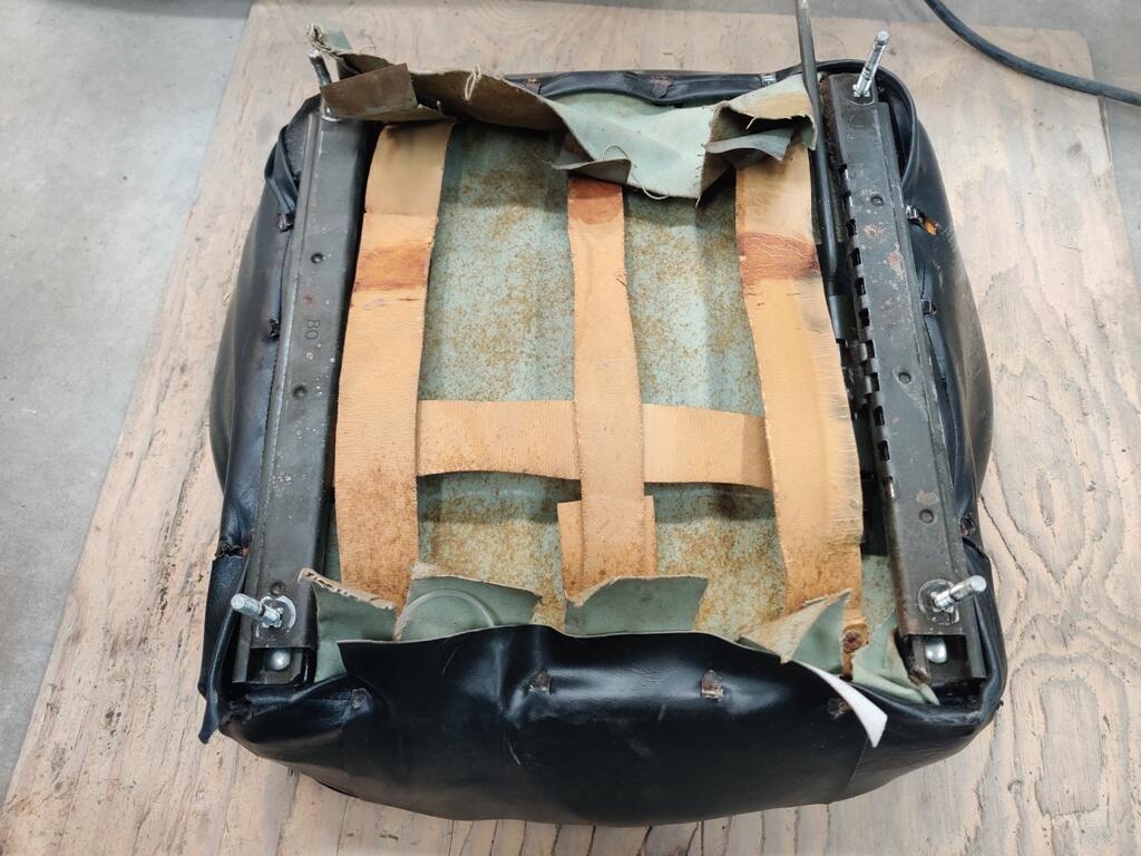
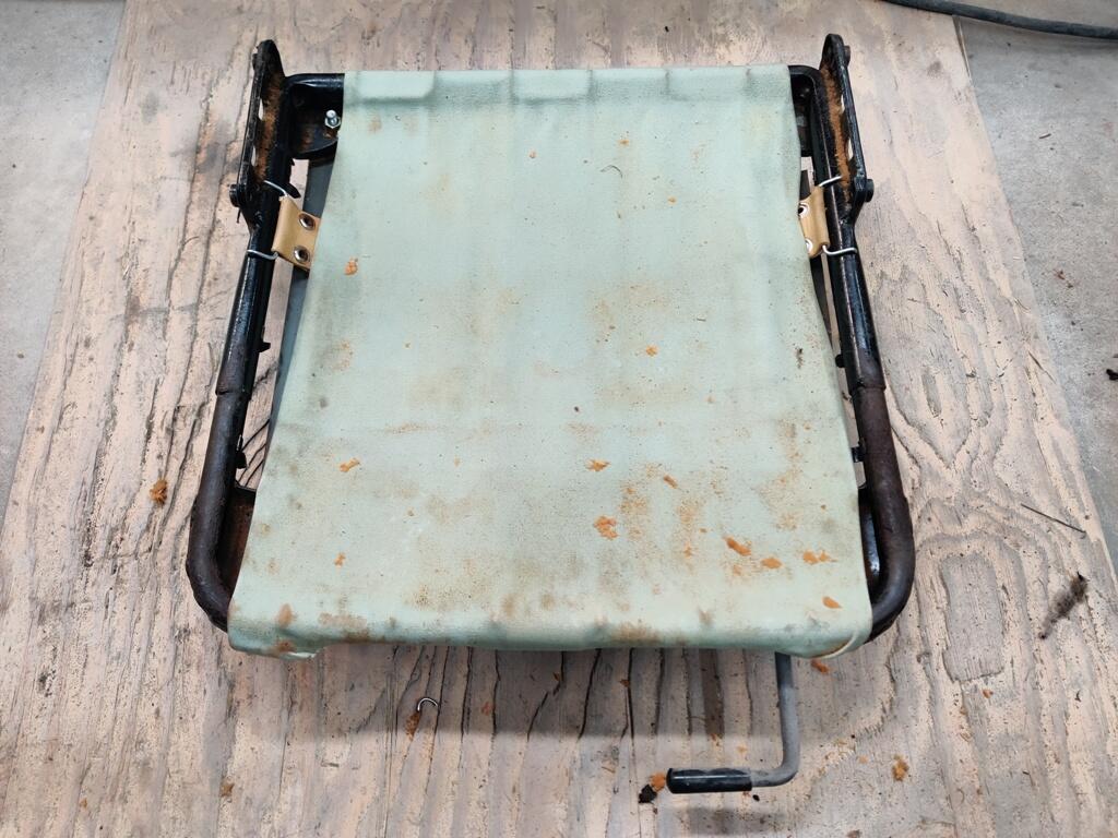
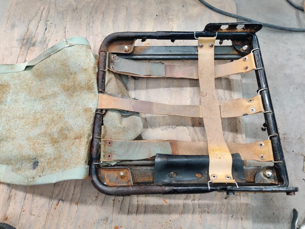
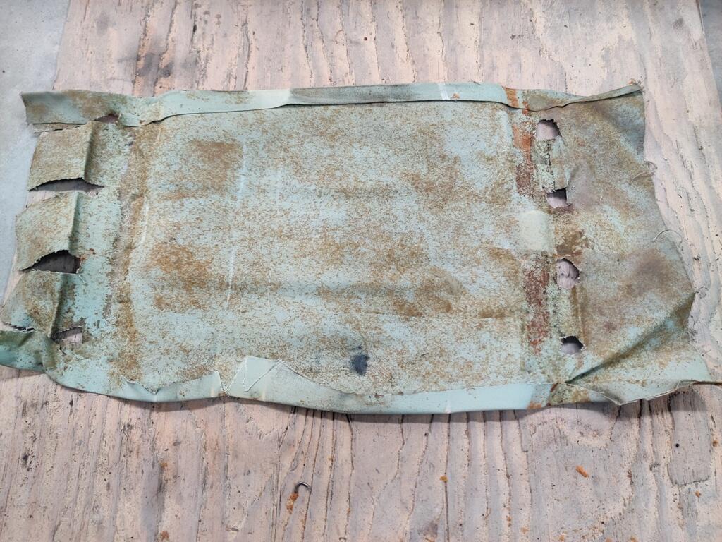
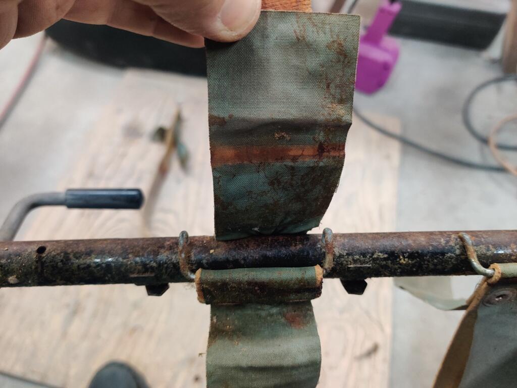
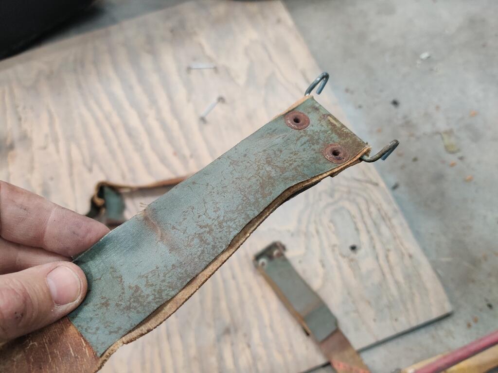
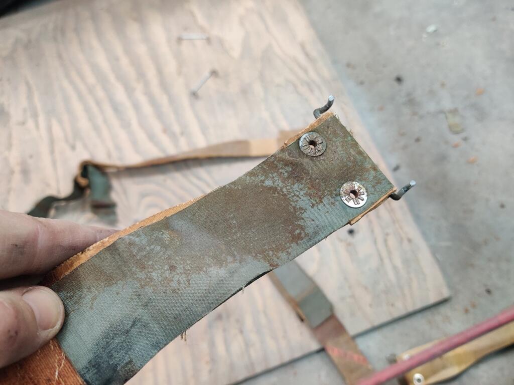
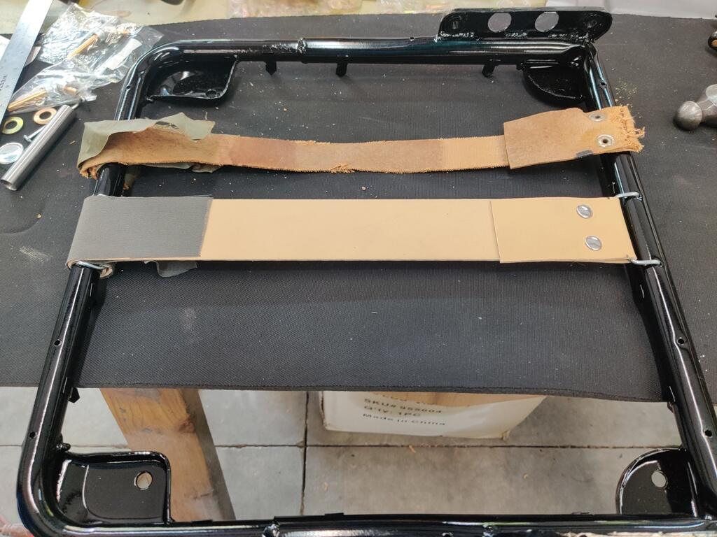
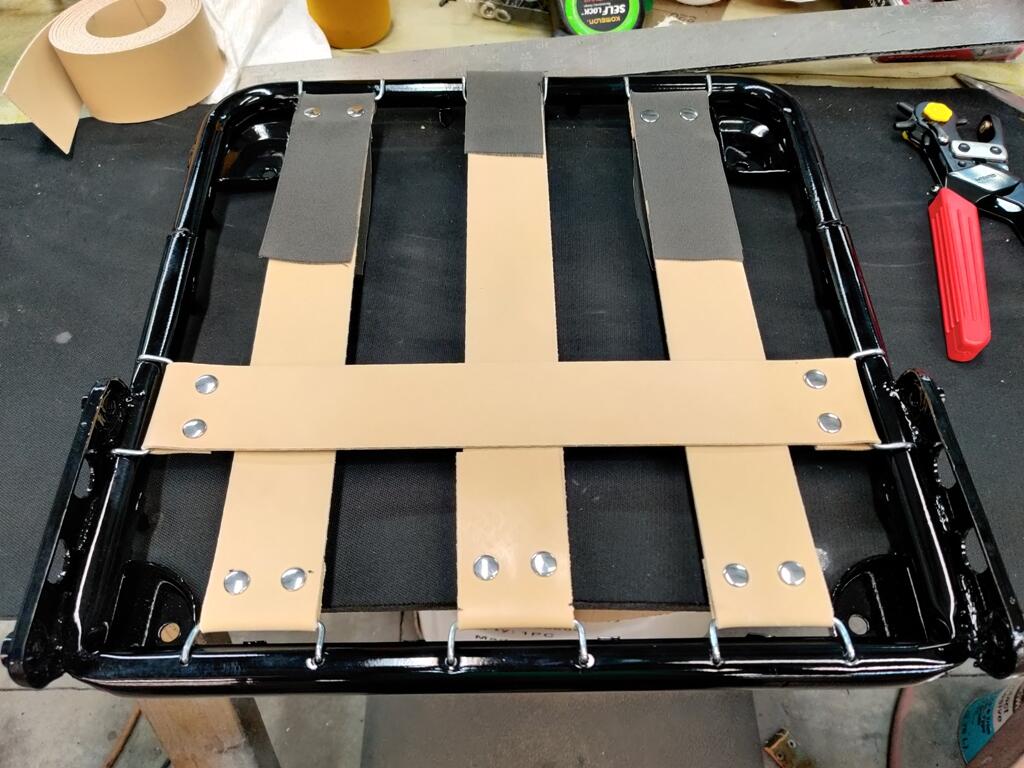
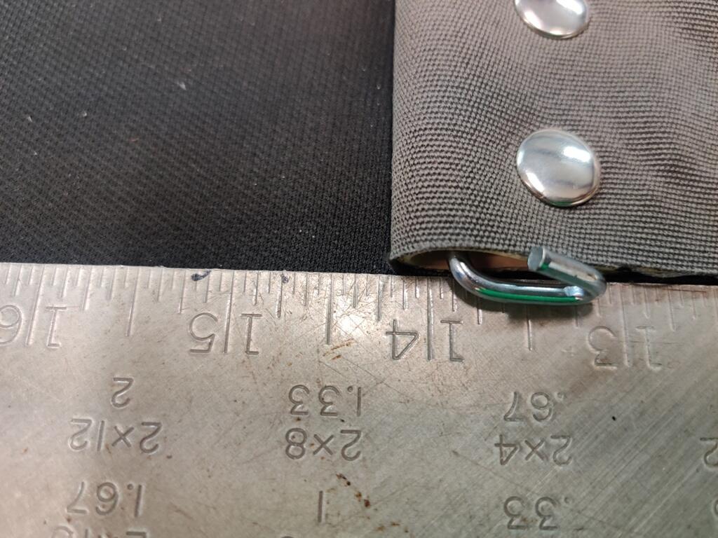
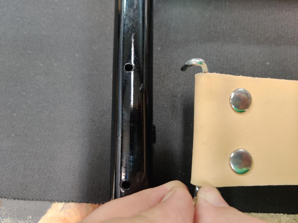
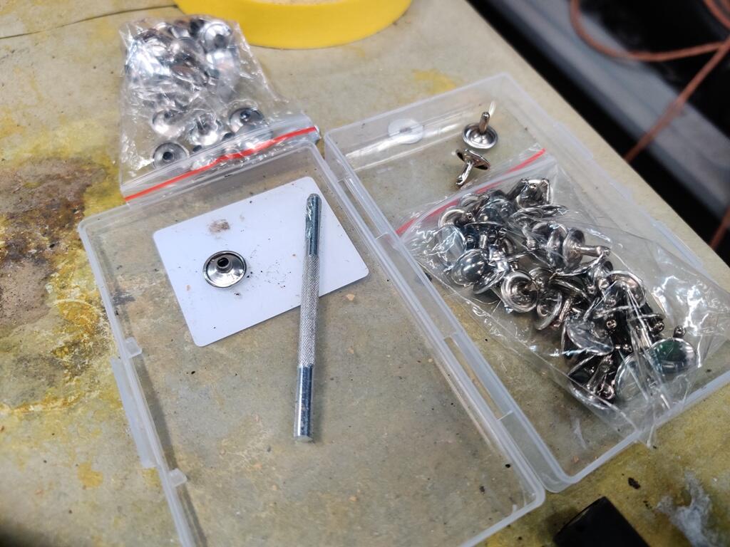
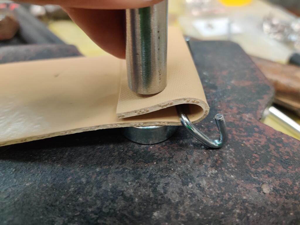
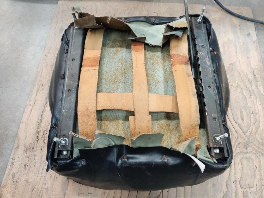
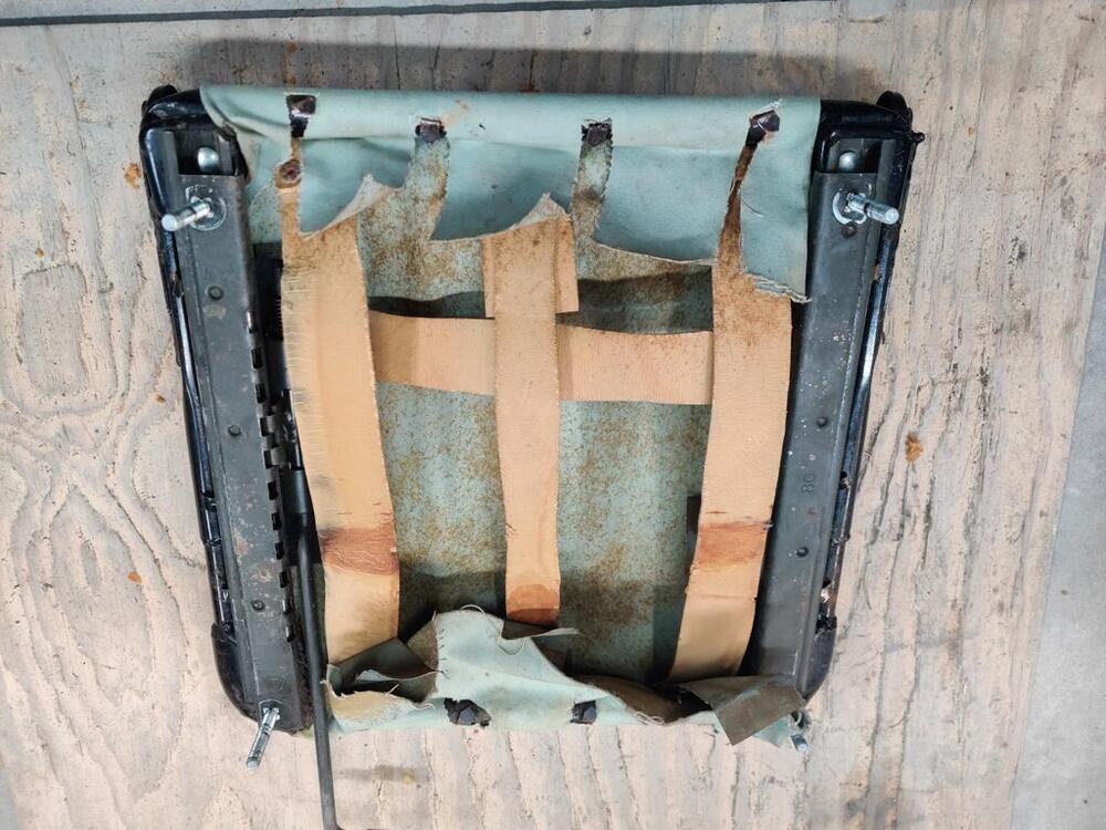
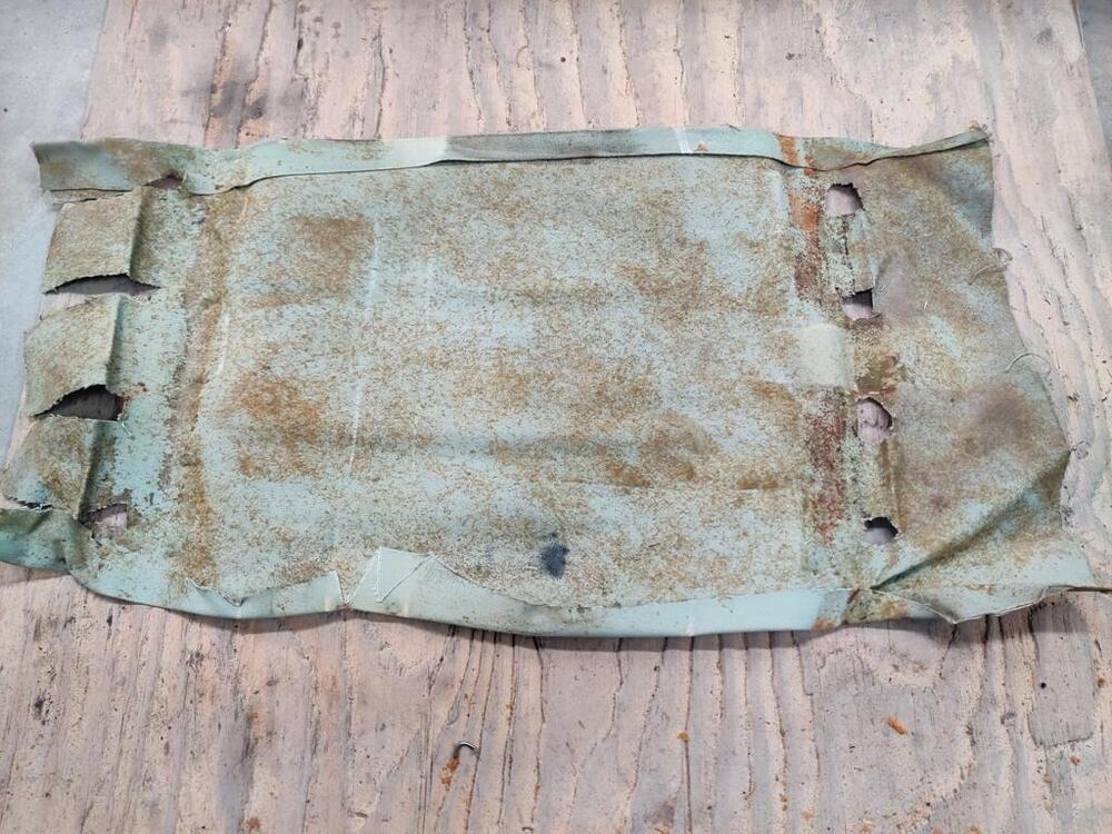
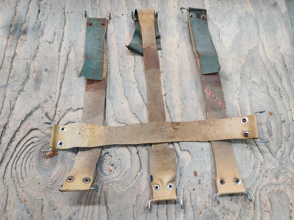
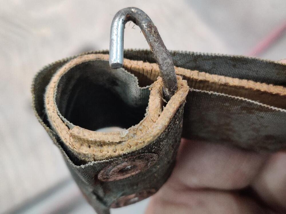
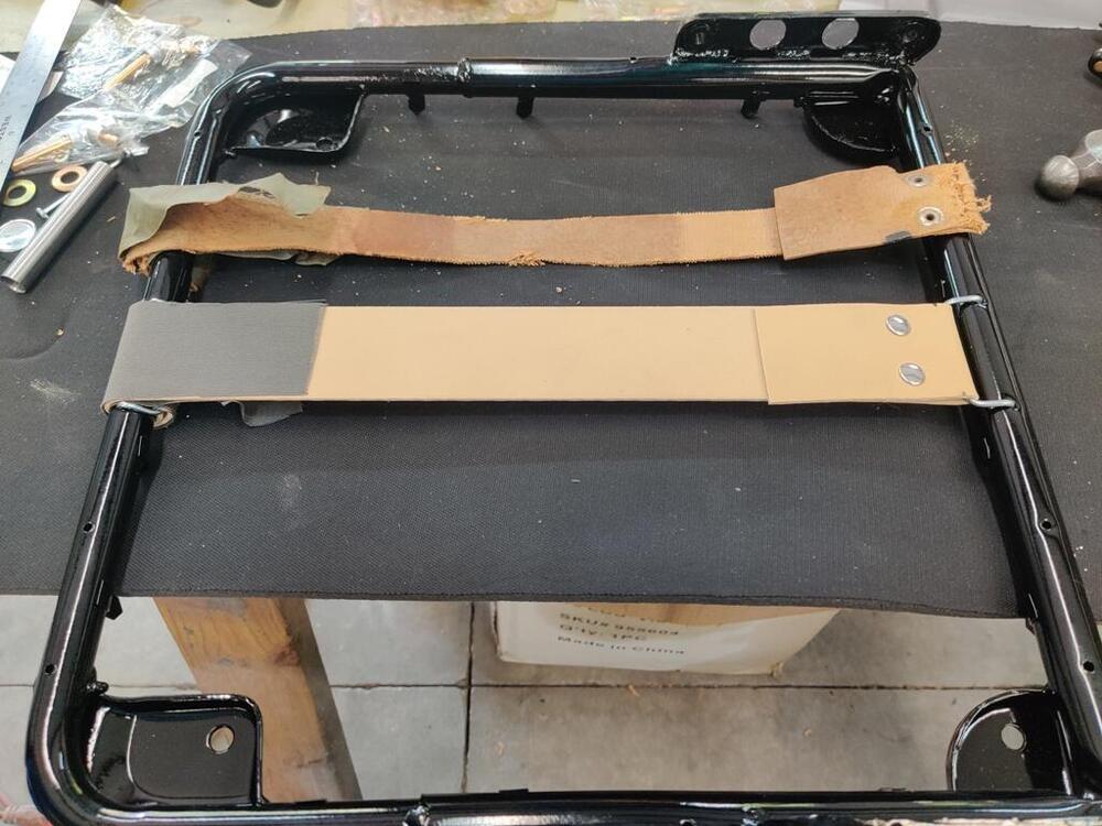
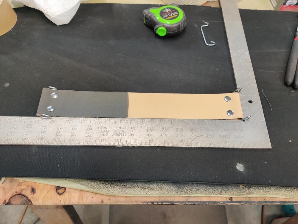
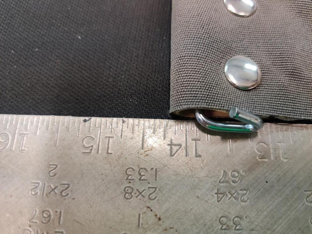
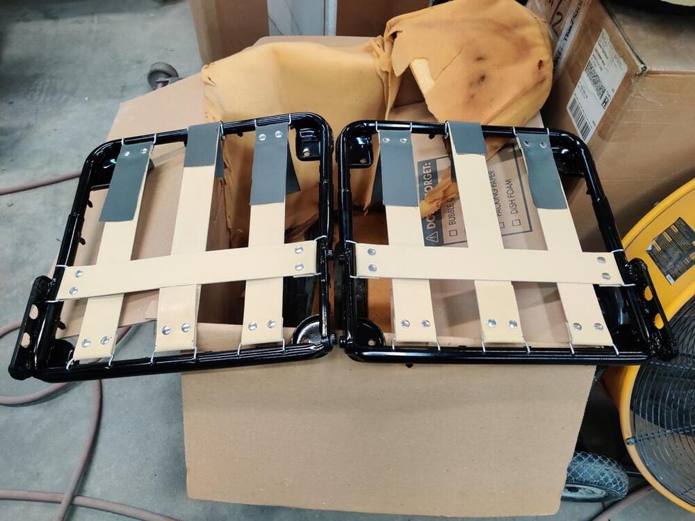
I have started rebuilding the seats. These were reupholstered once before. I have come to realize that this sheet of canvas material on top of the dry rotted straps is not original. I took many pictures as I was taking the seat apart so I would have documentation to refer to when it came time to reupholster them. I suspect that the center strap was folded around the front of the seat frame when the seat was reupholstered. Perhaps they tried to put some tension back in the "stretched out" strap. None of the other straps in the seat were installed that way. I believe I have made a mistake in reproducing this and will revisit to make the center strap not roll around the frame like this. The straps have some cloth tape at their front ends. It doesn't seem to serve any purpose to me. Seat frames and backs were "sand" blasted, epoxy primed, and finished in gloss black. Hardware was re-plated. I bought a re-strapping kit, but decided to go with "Pirelli" strapping instead. I don't know if it is better quality, but it looks more original and feels like higher quality to me. The amount of effort it takes to stretch it feels noticeably more to me. I bought a kit of stainless steel tubular rivets to secure the straps to the clips. Harbor freight sells a nice hole punch tool that I used to make holes in the strap material and the replacement canvas I bought. I installed the replacement canvas just for kicks to make mimic the factory cloth tape. Probably shouldn't have bothered. Assembly of the rivets consisted of pushing the one with the post through the materials and putting the other half of the rivet onto that post. Then I set the rivet with post into the round die and used a hammer and included setting tool to smash the two halves together. I experimented with lengths of strap to get tension where I felt it should be. For each piece, I landed at overall length of 17", and then folded over the ends so that the fully assembled strap was at ~ 14 and 1/4". To install them to the seat frame, I had to stretch the strap and drop the hooks in the holes. I estimate that I had to stretch the straps about 1 inch to install them onto the frame. I think my next step is to put the cover over the cushion material. I will do some online research before I attempt that part.


-
Ah - yes.
-
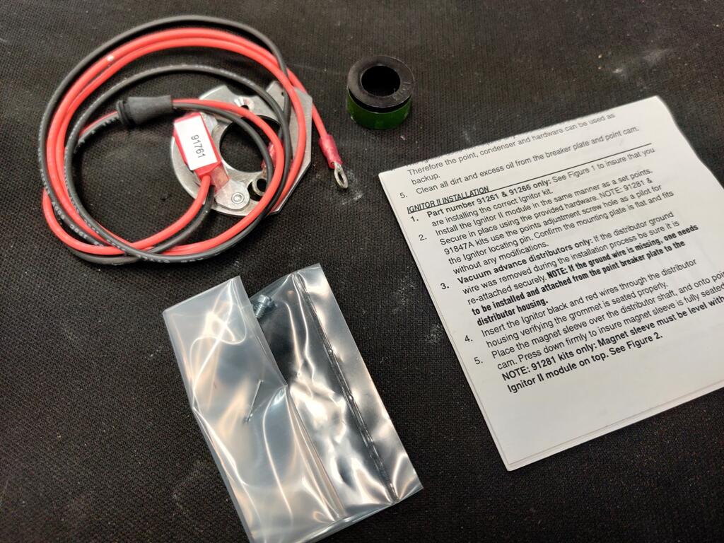
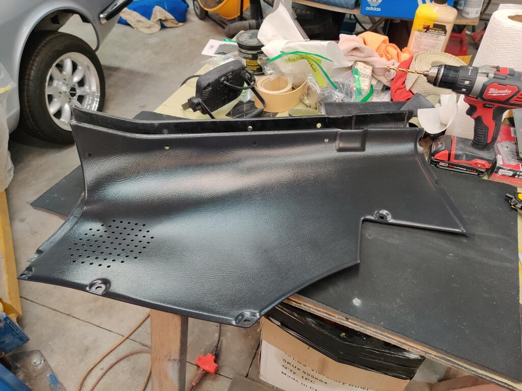
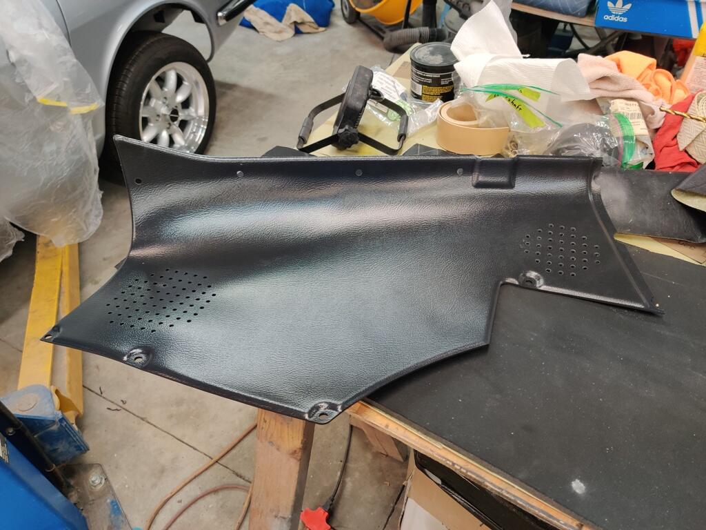
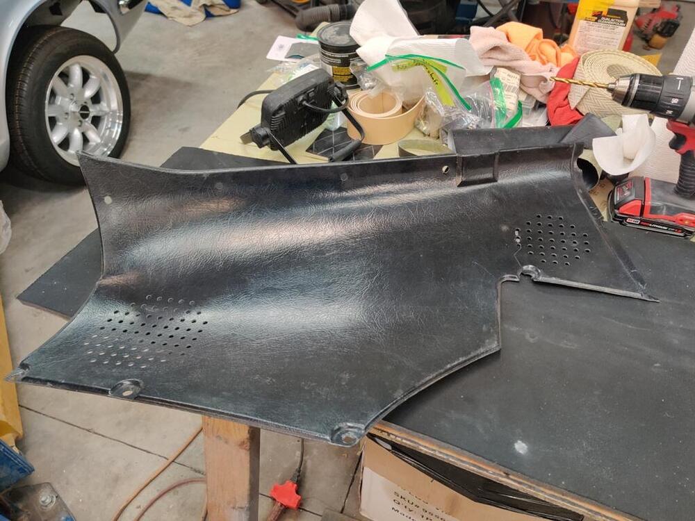
Today, I took a 1/2 day off from work and worked on the car. I was able to get the driveshaft measured properly. I will be sending it off tomorrow for shortening and balancing. I installed the Pertronix electronic ignition. I didn't take pictures, but I ended up modifying the distributor cap a bit to allow the wires to exit the distributor. I just drilled a hole and used a dremel a bit to get the boot that came with the kit to fit snugly. Next, I did a modification to the new interior panels I bought. I purchased the whole set of new, black panels (roof bar, quarter window, rear hatch, and tail light) from Z Car Depot. I also was able to source new SU nozzles from them. First, a comparison of the grain finish: Original and reproduction, in that order: The reproduction panels are nice. They are thicker and heavier than the originals. Instead of the hard plastic they seem to be made out of a slightly softer material. They only come in the early 1970/71 configuration. So, I drilled holes for the side pillar vent. New reproduction panel as received -- factory original panel -- and reproduction panel with holes drilled. I was able to clamp the original on top of the reproduction panel and use the original holes as a template. It came out nicely: Lastly today, I swapped out the new SU nozzles. While I was there I checked proper throttle plate opening when using the starter lever. When you pull the starter lever all the way open, the throttle plate to carb body clearance should be about .023" to .027". I also made sure to secure the cables at precise locations so that the nozzles both activate and move the same distance when the starter lever is pulled. I am getting closer to being able to start it up.


-
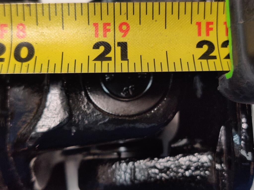
Yes, I think I will send my propeller shaft there (https://carolinadriveline.com/) as I had planned, but now it needs to be shortened in addition to getting it balanced. I just very carefully measured my center to center distance again. I got 21 and 1/8". Looking very closely, I think it is maybe .010 more than that. That is 536.829" mm. The factory shop manual says the length from center to center of the u-joints is 540 mm. There is no way this propeller shaft is that long between the centerline of u joints. Perhaps because there is a slip yoke, factory tolerance of propeller shaft length was not strictly held. After measuring carefully, I will be removing 2 inches from the propeller shaft. I suppose if I had the pieces in the car to move the differential back to align the drive shafts, this propeller shaft might fit as is. I seem to recall coming across that before in my internet travels. I could search to confirm, but it is a waste of my time as I won't be swapping in those pieces from a later car. If the drive shaft angularity causes issues on this car, I'll swap in some CV axles.
-
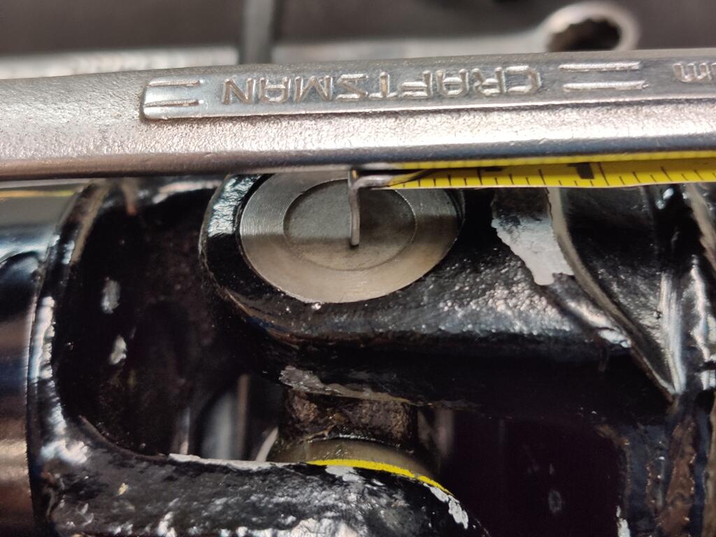
Hmmm. I am rethinking this. The driveshaft shield on the yoke is bottoming out against the 240SX transmission. And I measured the depth of that at 1.775". Just removing that shield might give me enough. I will need to have another, closer look.
-
I am thinking about using Inland Empire Driveline: https://www.iedls.com/
-
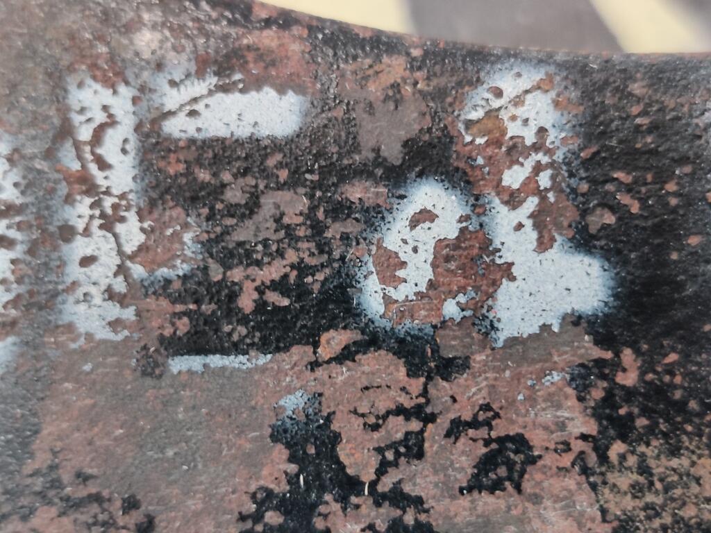
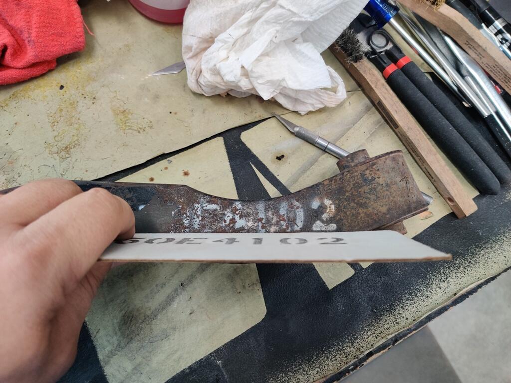
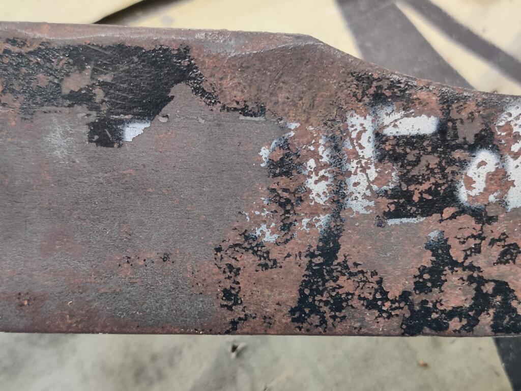
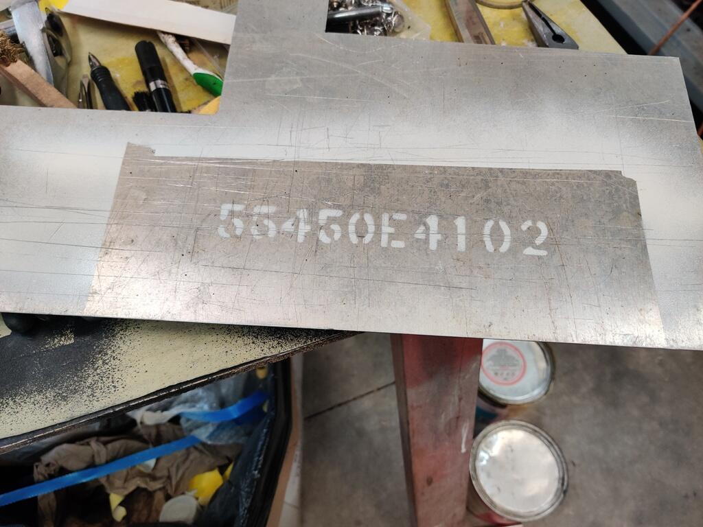
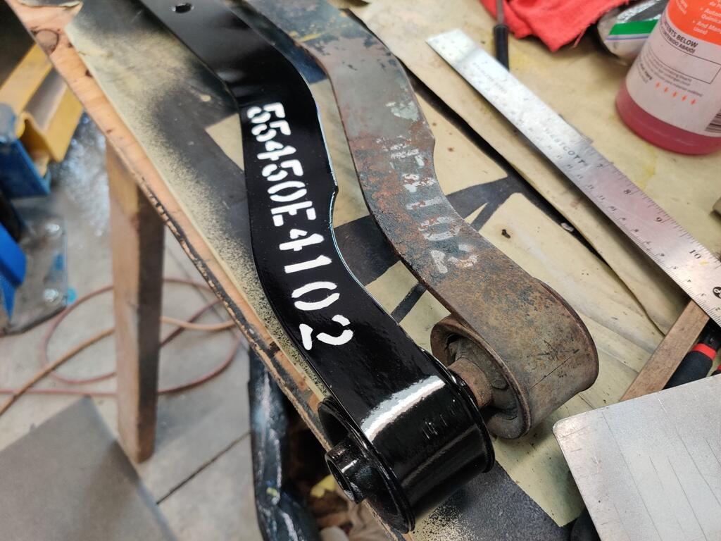
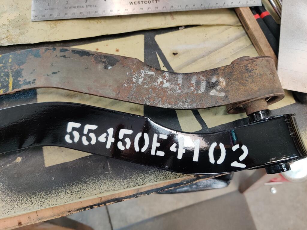
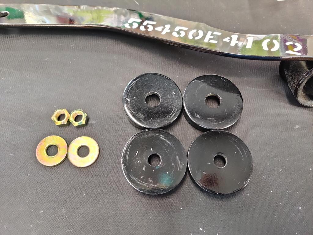
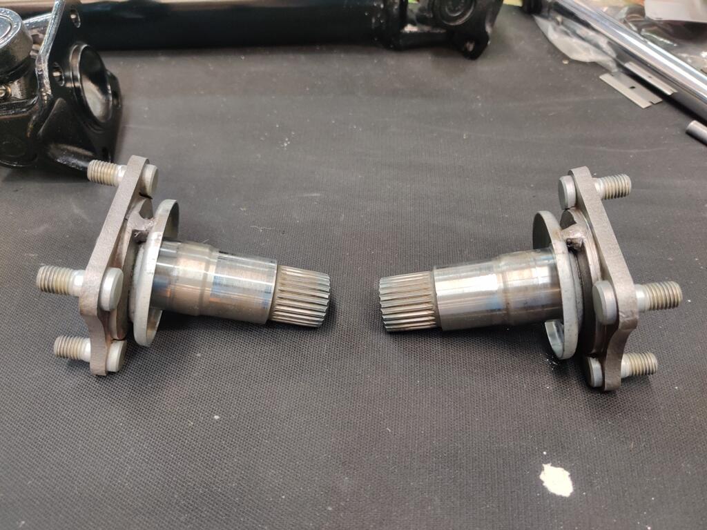
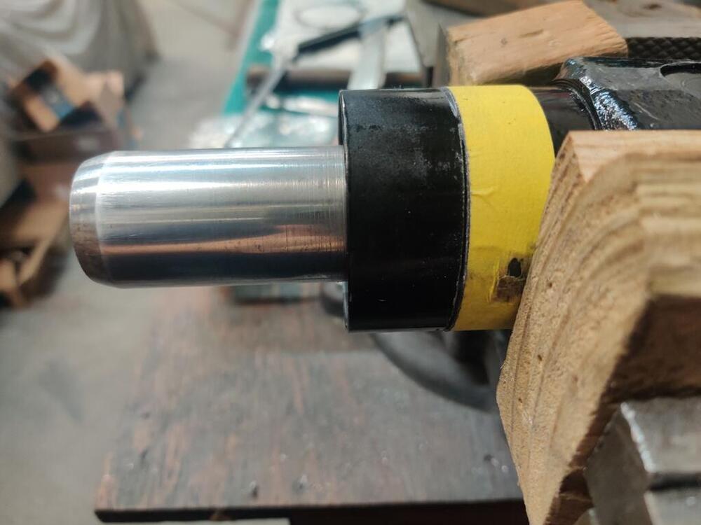
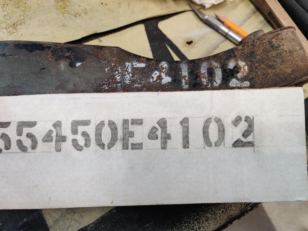
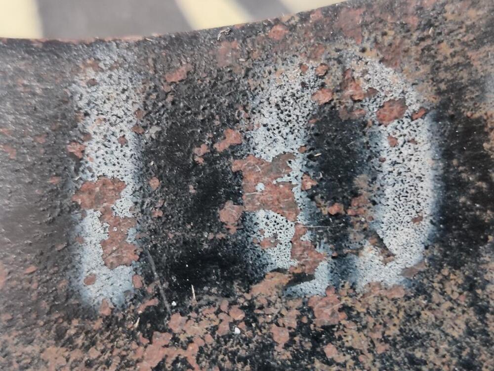
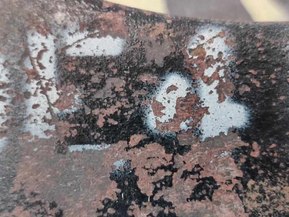
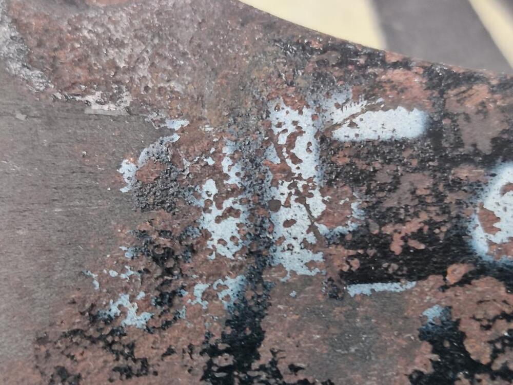
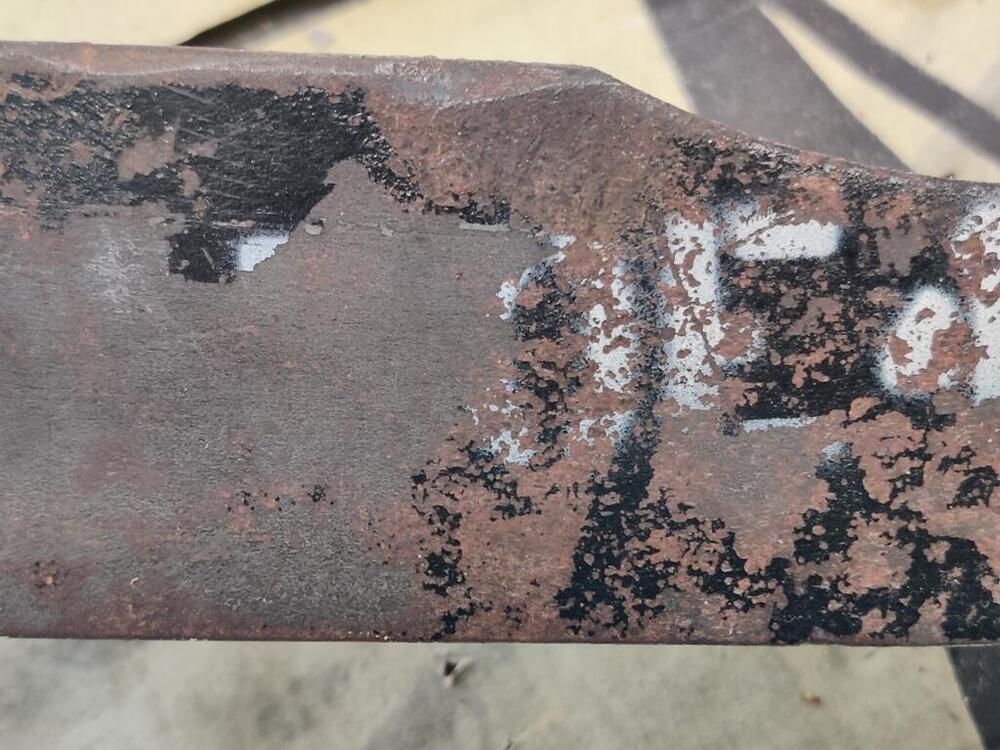
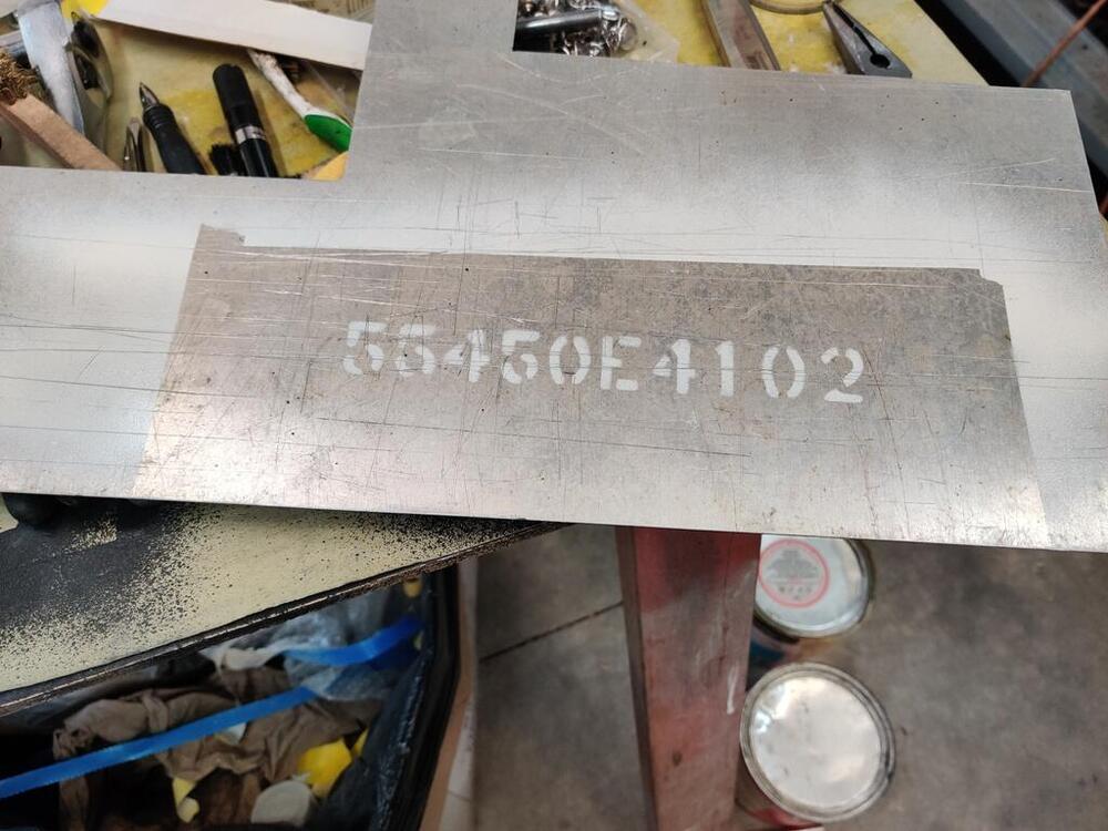
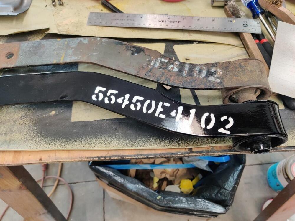
I made some decent progress today. I finished up the differential - here is the separate thread covering all the issues I had with it. I installed all of the oil seals and the rear cover. From there, I retrieved my "stencil" which was the result of many hours of drawing pretty much entirely free hand. I have a mustache bar with a portion of the letters and numbers in tact. Interestingly, though I have found a few pictures on the web with this same part number, I cannot find the part number listed in the parts manual. I am unsure what the difference is between 55450-E4101 and 55450-E4102. However, I think my car came with the E4102. So, I went with that number. If anyone has information to share about these two, please enlighten me. As can be seen in these pictures, the paint was sprayed on: I found a few things to correct on my stencil, so I did work on it some more before cutting the letters and numbers out. After I was done with the cutting, I needed to rest my eyes a bit - it felt like I was going cross-eyed when I finished. I made a test run on some scrap aluminum first. Being pleased with that, I aligned the stencil on the bar. On the old bar, the 4 and 1 were a bit too high for my liking, so I adjusted it so the letters and numbers would be a bit more centered. While not perfect, I think it came out nicely. Given the number of hours I have it, I am glad it turned out well. From there, I was able to mount the differential in the car. For the stub axles, I elected to glass bead them lightly and apply only some clear coat. These were not painted from the factory, so I kept that look. I found the stub axle retaining bolts to bottom out in the Quaife carrier. Luckily, I was able to stack a couple of washers to resolve that without causing interference with the bolt heads when installing the axles. From there, I grabbed the driveshaft to see if it would fit. And... not even close. I thought this was the "short" driveshaft, but it can't be. The short one fits when installing the 240SX transmission, but this one is way too long. It is the only one that came with the car (it was not in the car). So, it looks like I am going to need a driveshaft. I took several measurements. From center of the front u joint to the center of the rear u joint. It looks to me like it is in between 21 and 1/16 and 21 and an 1/8th. Since it is metric, I am going to guess it is 536 mm (21.103"). From the back face of the shaft to the center of the back u joint, I show about 1 and 3/8ths. Again, the closest metric measurement in mm is 35 mm (1.378"). For the front of the shaft, I measured two distances: from the tip of the input shaft to the front edge of the shield, and from the front edge of the shield to the base of the input shaft (inside the shield). For those I got 2.450" and 1.775" respectively. That totals 4.22 inches or 107.188 mm. Call it 107 mm. With these measurements, I should be able to get a custom driveshaft made that will fit nicely. I am not going to mess with sourcing a stock early one and rebuilding it with new joints, etc. I did that with the one I have and it was a lot of work to source new OEM joints, strip the paint from the driveshaft, install the u joints, and then paint the driveshaft. And, I would want to send it off for balancing too.


-
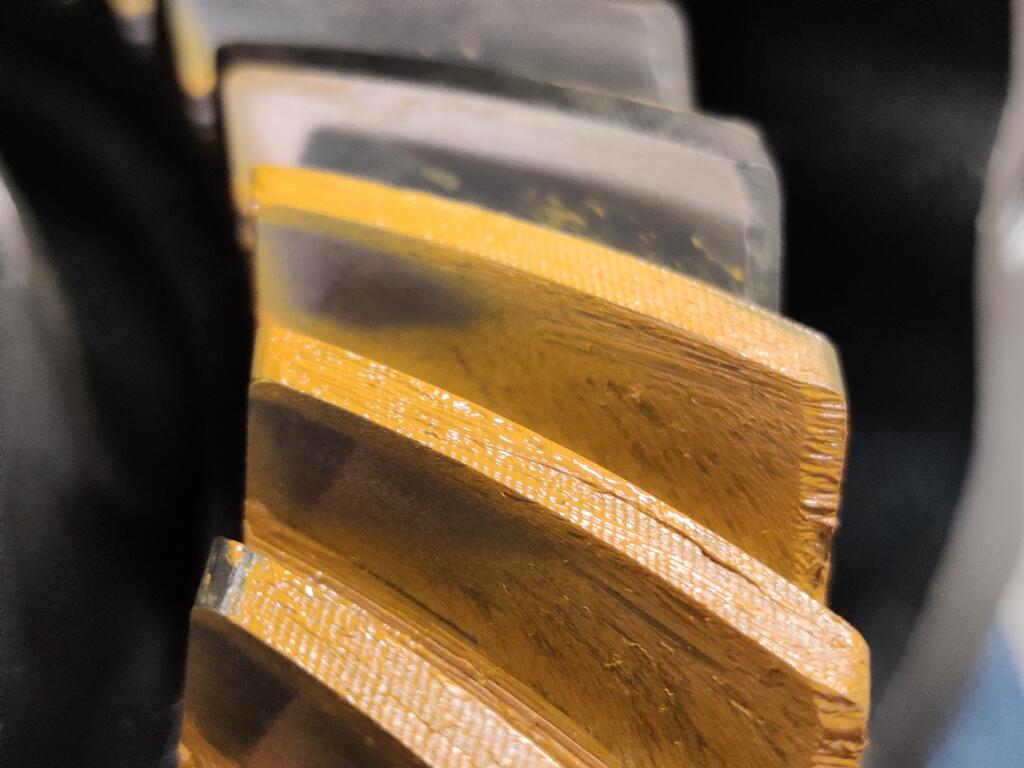
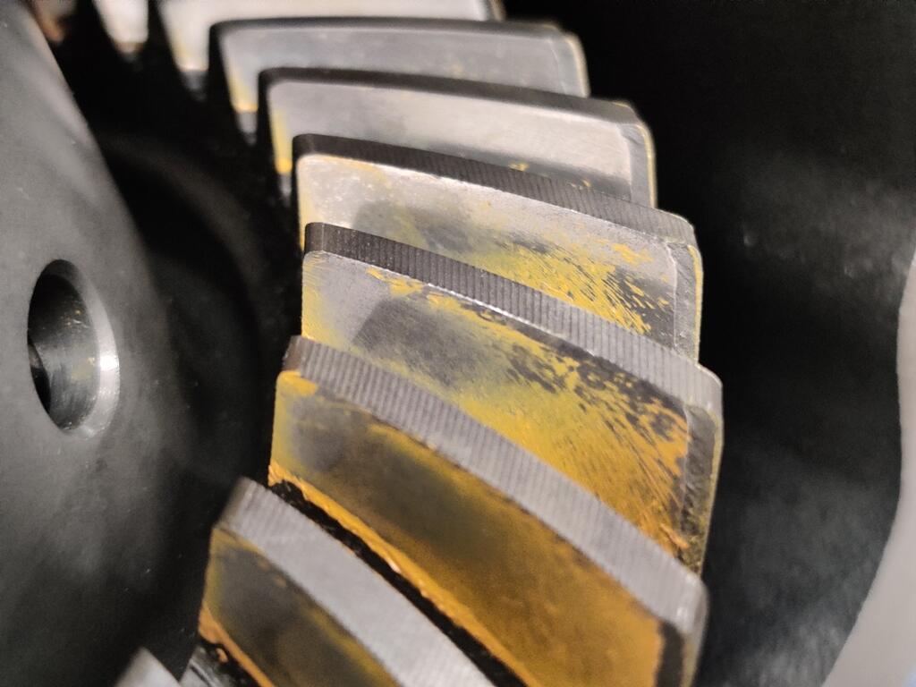
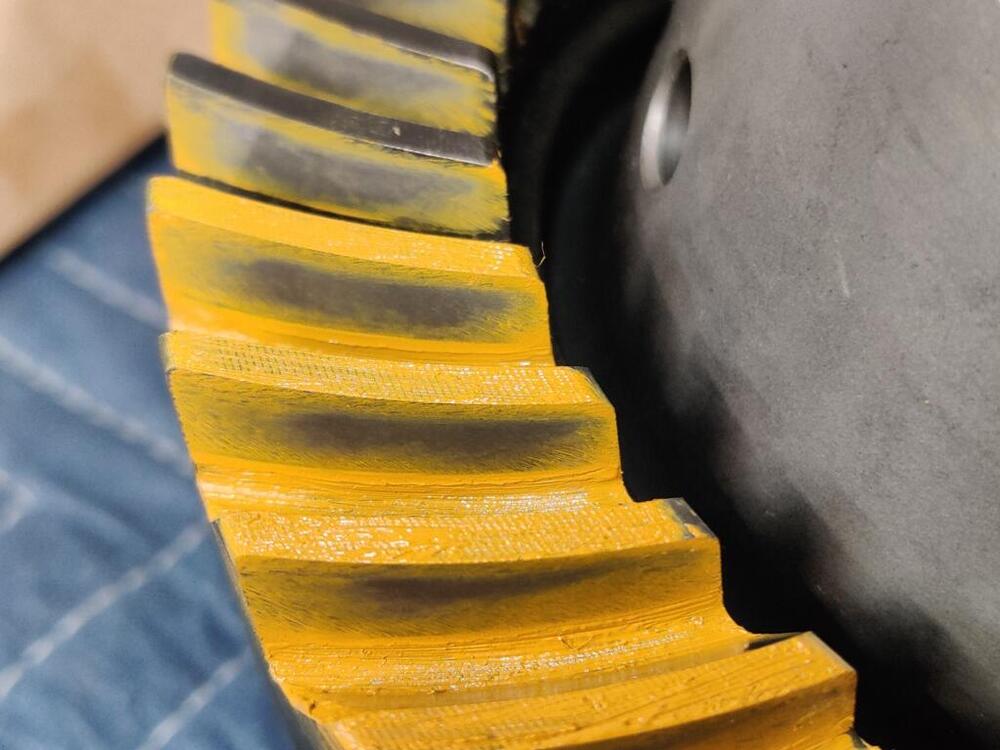
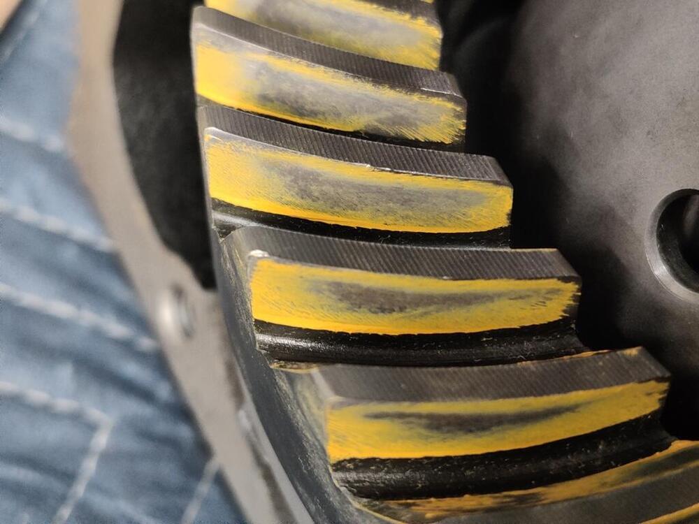
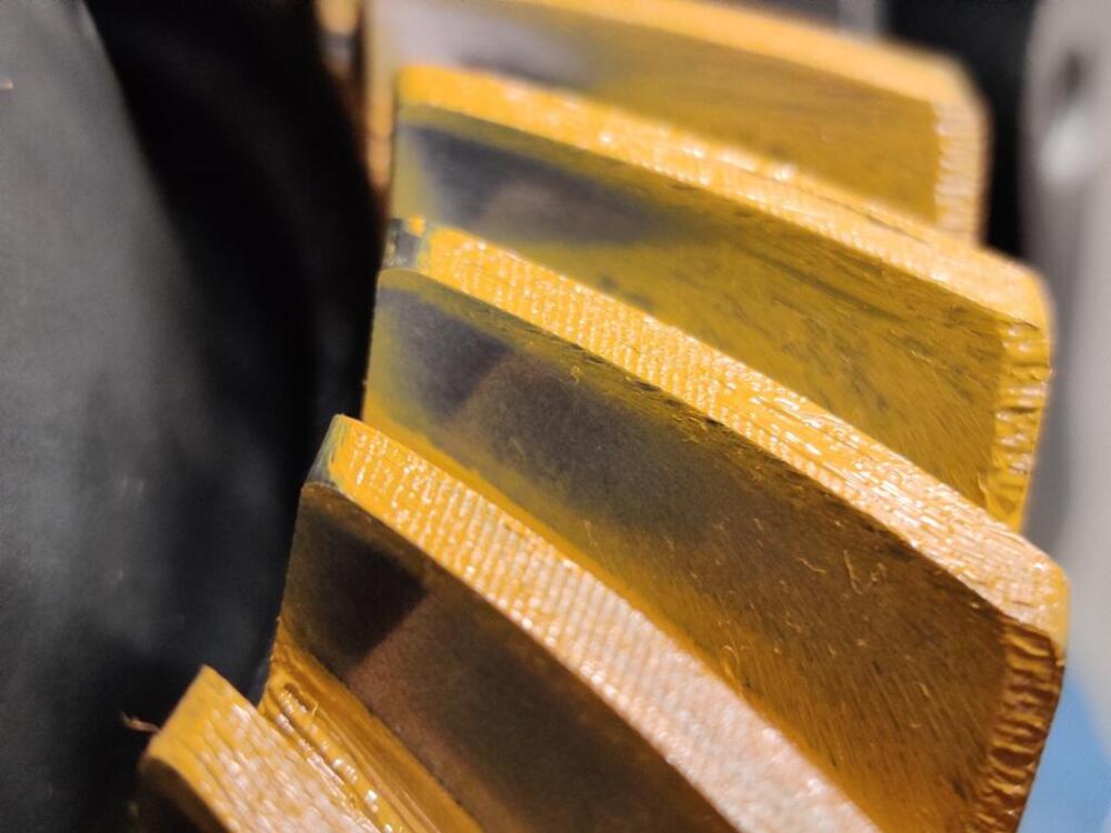
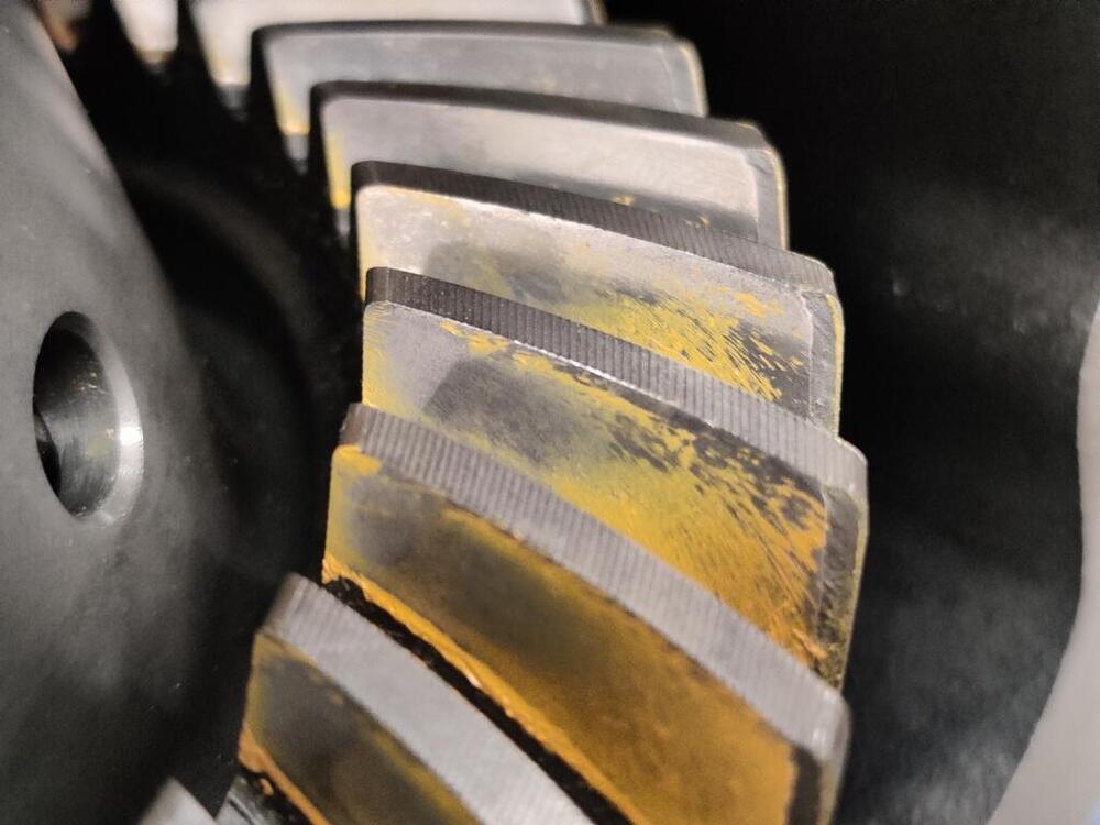
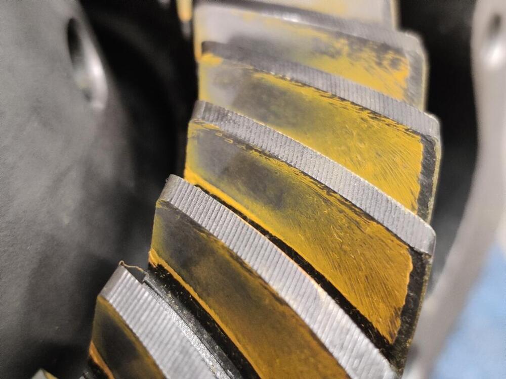
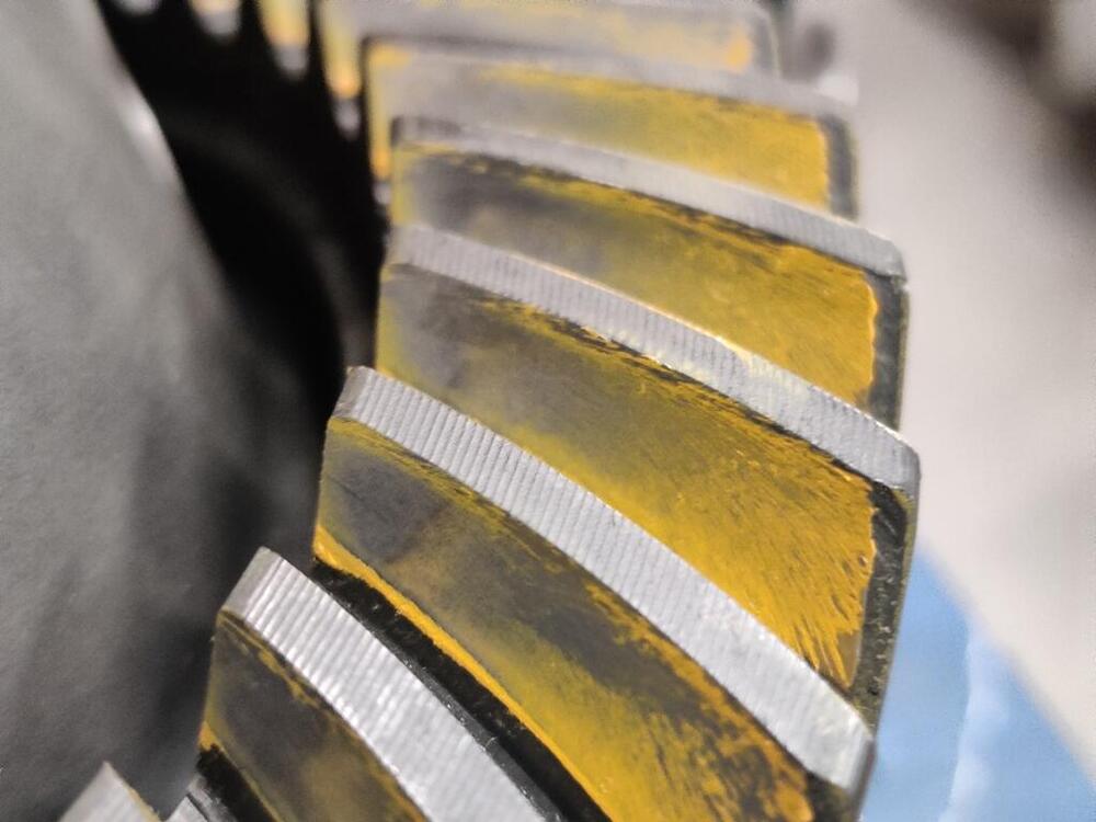
I was measuring runout incorrectly. I was measuring on the outside, angled edge of the crown gear. When I measured the backside of the gear, I got less than the .0031" factory specification. So, here are the wipe pattern pics: Drive side - first pic is directly painted teeth, second pic is the paint transfer to clean teeth. What I see here is that the contact area is nearly centered both from a top and bottom of the tooth and toe and heel of the tooth. The total surface area of the exposed metal (exposed by paint displacement) is much greater than my prior efforts where I was changing the pinion shim thickness. Paint is still present on the tooth surface above and below the exposed metal... and on the toe and heel of the tooth as well. This looks very good to me. Shifting now to the coast side of the gear: This is not as ideal. The exposed metal is mostly on the toe side of the tooth. It almost runs off the toe edge. However, I see a little bit of paint on the toe edge. And the surface area of exposed metal is quite wide and centered top to bottom on the tooth. I'd like to see the exposed metal area shifted more toward the center (with reference to the toe and heel) of the tooth. Looking now at teeth that were not painted: The pics above show paint that was transferred from the pinion gear to "clean" teeth. In these pictures it looks like the contact area is a bit more extensive. The width of the contact from top to bottom of the tooth is quite large. And the exposed area of contact appears to cover about 1/2" of the tooth between the toe and heel, mostly on the toe side. I am happy with the results I have achieved here. So, I will proceed with installing the oil seals and installing it in the car. It will be interesting to see how much noise this differential makes. From when I had it installed previously, I recall it made a low but noticeable amount of noise on deceleration, but it was quiet when under load. I had a 3.9 in the same car for a bit and it was incredibly quiet. I sold that one some time ago though as it wasn't the ratio that I needed. Net/net (summarizing this thread), I have installed the Quaife LSD carrier. I have replaced all of the bearings in the differential. I have reused the existing pinion shim and pinion spacer. In order to get the backlash within specification, I had to get the left side bearing retainer turned in a lathe to remove .5 mm of material, so that the retainer could recess that amount more inside the left side of the differential (when differential is viewed from the back). The .5 mm (about .020") which was removed was "replaced" with shims. I added back a .3 mm (.1181") shim to the left side bearing retainer, and put a .2 mm (.00787") on the right side bearing retainer with the rest of the shim stack there. It would seem that replacing bearings on the pinion with new ones was actually "no big deal" with regard to changes to the pinion and ring gear meshing. Swapping in the Quaife carrier caused the ring gear to move away from the pinion gear vs. the stock carrier. Also, replacing the side bearings in the side retainers did not appear to change the relationship of the carrier to the case either. I am confident in this because I checked the bearing preload on the side bearings at one point - the pinion gear was not installed, and I installed the carrier and checked rotation of the carrier. My check wasn't measured with tools, but by hand; however, the preload "felt" noticeable, but not "heavy". Anyway, I think I landed in a good place. I will be able to test that out now when I install the differential.

-
Ok, I am back at this thing! I sent the left side flange off to have .5 mm removed by lathe operation from the area indicated in the picture in the prior post. Tonight I found the time to mock things back up again and check backlash. With .5 mm removed, I put a .3 mm shim on the left side. Thus, I added a .2 mm shim to the existing set of shims on the right side flange (.3 mm .4 mm and .5 mm). In theory, the distance between the bearing races of the left and right side flanges is what it was before the lathe turning, though I suppose it could be a few "tenths" of thousands different. I don't think I can know for sure. Assembling and then measuring backlash as I have done before, I got .005" of backlash. Hallelujah! I did a quick and dirty version of checking the wipe pattern and it looks good to me. I will post pictures of that a bit later. One thing I did check and find out though is that while the Quaife unit has no measurable runout (checking with a dial gauge (units in .001") on the part of the carrier unit the crown gear bolts to, the same cannot be said for the crown gear. I ran the dial gauge against the gear and measured a bit more than .004" of run out. I am going to loosen the crown gear bolts and try to adjust that so it is within specification (.0031"). Stay tuned!
-
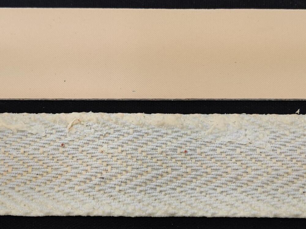
Should I acquire Pirelli strap material? The strap material I got from MSA is something else.
-
I am starting to rebuild the seats for my 6/71 240Z. I have this seat re-strap kit from Motorsport Auto, but I don't have any idea how much tension to put on the straps when I attach them to the bottom frame. The strapping material is rubberized, so it can be stretched. I am wondering if anyone has done a seat rebuild using this strap material and has any guidance? Once I determine the amount of stretch to apply, I will be marking the non-stretched length and the stretched length on a template for cutting so I can stretch them equal amounts.