EuroDat
Free Member
-
Joined
-
Last visited
Everything posted by EuroDat
-
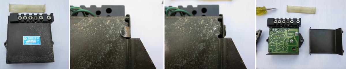
 You should disconnect the negative on the battery when working on the TIU, any electrical work (other than testing) for that matter. If you do choose to test the TIU this way, it would be the easiest for your situation. Remove the two screws holding the TIU and turn it around. Don't remove the wires. You will need a flat screwdriver and plyers to pry open the tabs and remove the cover. Once you remove the cover and fit the TIU back in its place the back side of the circuit board will be visable. That is what you spray with electrical cleaner. Just turn the ignition off and spray it for about 2 seconds and wait a minute or two for it to evapourate and cool the TIU. Then try to start it. If you buy a can with one of the thin tube nozzles you can lean over and spray it from the drivers seat. See photo for sets to take removing cover. You won't need to remove the TIU like in the photos. Contact cleaner I used, but any contact cleaner spray will do. http://wd40specialist.com/products/contact-cleaner/ I think you need to varify the Starter fluid test is not working before you move forward. I know everyone has their tried and tersted methods for testing. I found spraying it down the air cleaner for 2 to 4 seconds while someone tries to start the engine works fine.
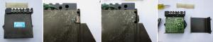
-
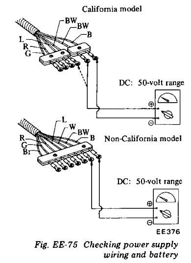
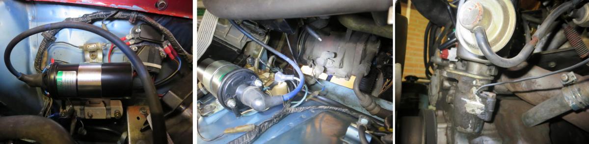
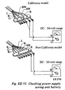
Jai has a 1976 model which had two versions for the TIU (Transistor Ignition Unit). The californian model looks just like Siteunseen's photo and the federal version will have an aluminium casing with cooling fins. The federal version also have dual pick-up in the distributor. The FED used a D6F4-01 & 02 dual pickups for manuals an automatics. The auto had 2° more advance when hot. The Cal version was D6F4-03 singel pickup. There are a couple of ways to tell them apart. 1. If you look at the terminal block next to the coil. The FED models have 4 wires coming out of the distributor (2x Green, Red and Brown) and the Californian has two (Red and Green) 2. The TIU in the FED model has a one piece terminal 7 wires going to the TIU. The californian model has a two piece terminal block and 6 wires, See photo Siteunseen post #95. A photo of either will tell which type of system it is. BTW: I starting to loose track of what it happening with the starting issues. A lot of posts in a short time. I assume its starting and running until it gets hot then stops and will not start/run which sounds a lot like a failing TIU. Cooling it is a good test. Cool packs will work, but they take a while to remove the heat. I removed the cover on mine and mounted it back in position without the cover. When it stopped I could spray the circuit board with electrical contact cleaner and let it evaporate to cool it quickly. It started straight away after that.
-
I have used both methods and both worked. The manifold test work in one case. I had a lot of water in the fuel and it wouldn't do anything. The other case was a bad ignition module that would stop working when it got hot. I was on the side of the road and the air cleaner was the quickest access. I did take the air filter out and spray down towards the afm while starting the engine. For the manifold method I used the brake booster port. It will mostly run on the back three cylinders with this method (because the brake booster port is at the back of the manifold), but it proves the ingnition is working or not. You are not ment to run the engine on this stuff. Its just to identify what is not working: fuel or spark.
-
If you have to use heat. Try not to get too much heat into NP valve. The rubber cups will be worthless and they are NLA. Instead, heat the nut til its almost glowing and let it cool. When it heats up it will expand and when it cools down it will shrinm a fraction. That might just be enough to get it out. After it cools mix up a batch of 50/50 acetone and auto transmission fluid. Spray or brush it around the nuts and leave it over night. That will work its way in. The next day try to remove using the tools Zed head described. Removing brake lines is up there with removing spindle pins. Once you have mastered the art of removing these your a pro. Goodluck.
-
If the master cylinder and rear wheel cylinders pistons were frozen then your NP valve is most likely full of gunk and could even be seized marginally operating. My brakes worked find and just passed a roadworthy test when I replaced the MC and the wheel cylinders. I cleaned the NP valve and the switch. They were both full of sediment and sludge, but cleaned up ok and thats a couple of years back and no problems since.
-
I can't make out what those sockets sizes are. Im having trouble with the ebay links. The spark plugs should be 13/16" . See the link here. http://www.homedepot.com/p/Husky-3-8-in-Drive-13-16-in-Spark-Plug-Socket-H3DSPSKT1316/202913555 Your heat gun could be ok. It needs to generate more heat then a hair dryer. A hair dryer doesn't have enough heat and a paint stripper can have too much so its actually somewhere inbetween. My gun has 2000W which can reach temperatures around 500 degC (about 930deg F). I have seen these solder sleeves, but never used them yet. They would make joining wires a lot easier. http://www.amazon.com/Waterproof-Solder-Shrink-Connectors-Soldering/dp/B00KU0V586/ref=pd_sim_200_4/190-5064787-0973753?ie=UTF8&refRID=1JEKTM0XYJ39PRFK6R5Y The tune up kit probably wont solve your problem, but its not a bad idea to change those items. I understand not having a car to get around making things urgent, but I would try to hold back on ordering too much stuff before doing any testing. Considering your financial situation you may need to buy something that costs more, but the budget is depleated and you will need to wait.... Starter fluid is a great diagnostic tool. Then your can test if its fuel or ingnition (spark) related. Chas
-
Rossi, If it goes into reverse without grinding then the clutch is disengaging properly. If not you can check the slave cylinder travel. It you have someone press the clutch pedal all the way in and you measure the travel at the end of the clutch fork. If everything is adjusted properly and you are getting around 15+mm you should be fully disengaging the clutch. The slave cylinder should have around 10mm "free travel" to compensate for clutch wear. You can check that by pushing the spring back and measing the distance. If you heve something like 20mm, then you could have a mix up with the bearing collar and pressure plate finger height. Yes there are a lot of combinations out there in datsun world. Another test. Hold the clutch pedal in half way down and check if the fork slowly moves back to released position. Don't do this test with the clutch pedal fully depressed. That is where the master cylinder is at its best. Pitting and corrosion tends to concentrate along the bottom and a little more at the front end (push rod) of its travel. I think your problem is in the synchros and the PO tempering with it is also suspect. Synchros can be funny things. They look get but work like crap. A friend had a set that look worn, but they worked fine. He ordered new aftermarket synchros. We put them in and it was horrible. PS: My question on the slave cylinder push rod. A lot of people think because "they" can't adjust it, its not adjustable. It is completly self adjusting. If everthing is working it will compensate for clutch wear and remove all the free play out of the system by the spring in the slave cylinder expanding when everything is at rest. The adjusting only falls down when people start changing the type of throw out bearing collar / pressure plate or incorrectly adjust the clutch pedal. Note: If the pedal is adjusted to tight the mc primary seal wont pass over the reservoir port. This will effect the self adjusting action of the slave spring. Chas
-
Rossi, Chickenman quoted GM transmission oil (Friction modified) in another thread. Maybe he will chip in, I can't find the thread atm. It must be the friction modified version. I can't get it here so I can't talk from experience. Im using Redline MT90 like ZedHead and I find it to be a very good oil for these transmissions. My experience. What do you expect to accumplish with an adjustable push rod? How much free travel do you have on the slave cylinder? If you push the clutch fork into the slave cylinder, you should get around 10-15mm free travel. Depends on clutch disc wear and pressure plate/throw out bearing collar combinations. The balls and spring will help the shifting, but won't do anything for the grinding into gear. That can be a synchro issue or a clutch disengagement issue. Even a dry spigot bearing in the crankshaft or dry clutch plate splines can cause extra drag where the weaker synchros with give up and cause grinding. EDIT: Found the thread: http://www.classiczcars.com/topic/51698-how-should-a-71-240-4-speed-feel/
-
Rossi, Here are some other threads with similar problems. The first one has a lot of pictures http://www.classiczcars.com/topic/51155-tranny-piping-out-of-third/ http://www.classiczcars.com/topic/45755-shifter-return-spring/ http://www.classiczcars.com/topic/46725-weak-return-to-center-spring/
-
Hi Rozzi, You mentioned exposing the o-ring and you also mentioned a shifter lever pin, but was the stopper guide pin in place? It stops the striking guide from coming out. The striking guide should rotate and return to centre by the return plunger on the left side. It shouldn't move back and forward. Sounds like your stopper pin is missing or damaged in some way. I have posted a this in a couple of threads. I would start by replacing all the check balls and springs and return checker plunger and spring. You can't change the interlocks without dismantling, so don't worry about ordering them. While you are at it. Buy all the shifter bushes (2x side bushes and the end cup). All this stuff will set you back $20 at your local Nissan dealer. Its all "do"able without dropping the transmission. The top check ball and spring are a pita. I bent a ring spanner to get to it easier. You will need to remove the console to get to the shifter. I know some people will say that there could be wear inside the transmission. True, but this is often enough to return the system within spec and eliviate the problem. Parts list 2x Shift lever side bushes. 2x Shift lever lower (cup) bush 1x Shifter lever pin (Optional) 3x Check balls 3x Check springs 1x Set Return checker springs 1x Return checker plunger (Optional) Don't bother ordering the o-ring or the little oil seal on the striking rod. You need to dismantle the shifter assemble/transmission to get to them and I don't think you need to do that at this stage. There are more things that can cause shifting problems, but your description of the state it was in when you got it, I would start with these easy/cheap fixes. Another thing is to use a sealant on the the spring caps to prevent them leaking and coming loose. Doesn't hurt to use silicone sealant around the stopper guide pin. Its on the transmission side of the o-ring an can leak a little oil. An hours work and your should done. An aircraft technician managed it . Zed will understand that . Chas
-
That is what I like about this site too. The members are friendlier than other forums Im in. I don't know why the others seem to be so "agressive", there is no need for it. Unforntunatly I can only offer advice and mental support. Back to Redbird and redwing. I think when you weigh up all the pros and cons the 280Z still seems to me to be the best option for your current situation. If funds were not a problem than the 240Z would than be a better choice. Some more photos of redwing would also be helpfull. Redwing has been sitting in the weather for 8 years and I persume something went wrong with her before she was parked. If I was in this situation with all the history around Redwing I wouldn't sell her. I would try to preserve her more. Just sitting in the outside elements like in the photo don't do these old cars any good at all. And you never know what opportunities may just be around the corner. Once you get an fsm, you can read up on the tech stuff and start doing some fault finding and assessing the situation before spending any money on both the Zeds. I wish you all the luck with your endeavours. Maybe Steve wiil come to the rescue. Chas
-
-
Jai. I know it would be a hard dicision to make, but I think your best option is to move forward with the 280Z. Be carefull with sentimental value, it can come at a cost and that is what you are trying to avoid right now. Point is; The 280Z was runnin recently and the 240Z was not. Looking at the photos, I think you will come across a lot of hidden problems and the assosiated costs. Penny and dime costs can really add up. If the fuel injection is causing you a lot of grief, than the carby swap from the 240Z could be your best alternative. Fault finding, especially the way most of us do it, is to replace suspect parts. Doesn't mean that part has failed completly, just highly suspect. If that doesn't fix it you move on to thenext item in the list of suspect parts causing the problem. This is not a very atractive option for your sistuation as it can run into high costs. The FSM will be your first step and then diagnosing the problem and how to best approach it. Can you join a local Z club? That you be a good move. Most clubs have members that are friendly and eager to help. Chas
-
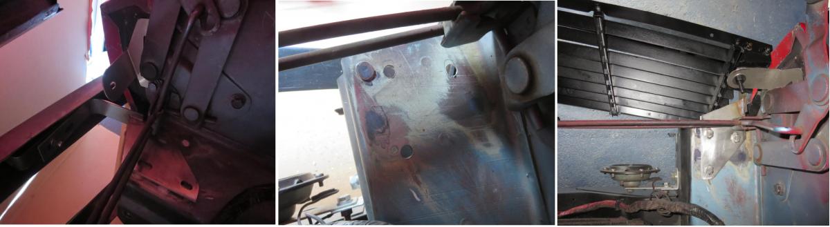
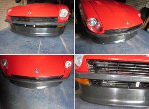
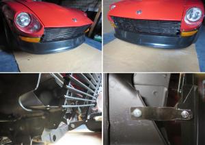
Its been a while, but it been just too bloody hot to work on the car lately. I've had the bumper brackets a couple of days now and decided to brave the heat and fit them today. All the brackets so far are hand made and a little shabby here and there because I have been making corrections, redrilling, rebending etc. The final brackets will be cut with a laser and look a lot better than these. Just need to make the same adjustments in the dxf files. The bumper brackets are made from 3mm, but the final brackets will be 4mm. The 3mm would be ok for fibreglass, but I think they would be too flexable for the chrome or stainless steel bumper. Fitting the bumper bracket. Still need some washers and painting here and there. That will happen when it comes apart for the final brackets. Everything back together. If anyone is interested in a set, I plan to cut a couple of sets (while Im at it). A kit could include: 2x Bumpers brackets with ss bolts and nyloc nuts. 2x Grill top mounts. 2x Grill bottom (side) mounts. 2x Long vertical bars for the grill plus M3 bolts and nyloc nuts. (These are to convert the grill from 7 to 9 bars and lower the 240z grill centre anchor to connect behind air-dam) 2x Side vertical bars for 9 bars plus M3 bolts and two extra nuts for side mounts. 2x Brackets to mount the horn. (On the 77-78 the horns were mounted on the bumpers shock) Everything except the 4 verticle bars is made from Stainless steel 304, bolts and nuts are A2-70. The 4 verticle bars are aluminium. Instruction how to get there (without all the experiments I went through).

-
It could also be a compressor seal. That was the problem with mine. I found it by charging the system with compressed air and spraying the parts with a solution of dishwashing liquid and water. That and two leaking fitings which simply needed tightening. If you can determine the basic components like the condensor, evaporator, and compressor are leak free, I would go forward with fixing the original system. Remember, the prices you are qouting are for the system. It needs to be installed and the original removed. The biggest problem these old systems have when changing from R12 to R134a is the insufficient condensor size. It is too small to remove the extra heat caused by the higher pressure and therefore warmer in the cabin. Most compressors fail due to the mixing of the two different oils. Flushing generally gets most out, but there is also always some in the system somewhere. R12 systems used a mineral oil and R134a uses PAG or POE which is a polyester blend. If you use PAG when replacing the refrigerant the oil won't mix and they will coagulate in the system and the compressor will fail. If you use the POE oil it will mix with the left over mineral oil and work fine. Always change an old receiver/dryer. The filter will fail in the R12 dryer if you use R134a in it. I quoted the 77 fsm because I have it. There are probably some small differences. I know the vacuum tank was moved down next to the oil filter on the 77 for one. I have not read the 76 manual, but the principle workings will be the same.
-
It would be one of the conditions require for it to run. I think there would be more things to investigate before trying to start the airco. The fact that the bullet connector is disconnected strongly indicates it wasn't functioning when the PO removed it. More than likly no gas in the system or damaged compressor..... Some simple things you can check is for starters. Is the system complete. -Are all the A/C hose/piping connected and no visible damage. -Are the vacuum lines still in place, vacuum tank on the other side of the engine bay, fast idle actuator on top of the inlet manifold etc. The FSM has some good diagrams in the 1977 edition. See section AC-36 and AC-37 for the vacuum hose en electrical harness diagrams. There is also a good diagnostic system for trouble shooting in the FSM starting at page AC-40. The FSM has a good description on how the system works and what all the individual parts do. It would be advisable to read up on this before going any further. Background knolledge would also help if you when to an A/C service centre. If it all looks complete you could check if it has pressure. The compressor has to valves with caps where the hoses go to the compressor. They are use to service and test. You can remove a cap and check for pressure or get a specialist to check with his gauges. I doubt it will have any because it been sitting for a long time. Compressor seals tend to dry out and start leaking over longs periods of not being used. The next question would be what refrigerant does it have now, has it been converted? This system was designed for a refrigerant called R12 which worked at a lower pressure than the modern day equivalents like R134a. R12 was banned for enviromental reasons and the system will work on the modern refrigerants, but not as effective. It you do decide to get it working, don't expect to much from these systems. Its not a modern day system. No climate control or window defrosting, just cool air. Basic creature comforts....
-
Thank you CanTechZ. Im glad you came with the measurements. My fisrt etimate was 750mm which would have left me 10mm short on both sides.
-
Charles, Im planning to paint it once all the fitting is over. It is easy enough to remove and take it to the paint shop. Matching the colour might be an issue, but the paint work is shoddy at beat so a little mismatch way make it any worse. I have a question, maybe someone can answer. I am making the bumper bracket (or getting them welded together). What is causing me some concern is where to put the holes for the bumper itself. There are two bolts per bracket and they are about 33mm apart, I dont have an original bumper so I dont know how far apart the brackets are from each other. The bumper Im using is fibreglass and has a very long (80mm) slot so there is quite a bit of variance available. The plan is to change to the chrome bumper or maybe a Harrington stainless steel version later. That means if I don't get the brackets right now, Ill have to make them again later. I made a quick drawing to help explain what I mean. The ??? dimension is the one I need. Can't seem to find anything about it on the internet. Any help would be much appriciated. BumperBracket-1.pdf
-
I hope the Bloody Mary is after 8am.
-
100F already and the summer has just started. We have been having days here where it just reaches 15C (about 60F) and then a couple of days its around 25C (75F), but 100F would be a little to much for my liking. Here it gets too humid and sticky once its above 28C.
-
Its been slow going the last two weeks. I made the bumper brackets out of aluminium and now they are being fabricated out of stainless. I told him I wasn't in a rush because I had some other things to do first. That meant he left them in the box and forgot about then until I called last Monday. I should have them this weekend. After so many prototype aluminium brackets I finally got the grill where I wanted it. Then I made all the brackets out of stainless and did the final mounting of the grill today.
-
I like the palm tree in the background Its about time summer started here.
-
Let me think about this a little. If you paid them more dealer prep charges they would take parts of your car. Just doesn't sound right.
-
The difference in bolt head size is due to the two standards used. DIN931: M8x1.25mm = 13mm (min: 12.73mm) M10x1.5mm = 17mm (min: 16.67mm) M12 = 19mm M14 = 22mm M16 = 24mm JIS B-1189: M8x1.25mm = 12mm (min: 11.75mm) M10x1.5mm = 14mm (min: 13.75mm) M12 = 17mm M14 = 19mm M16 = 22mm
-
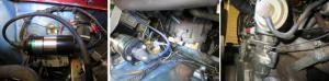
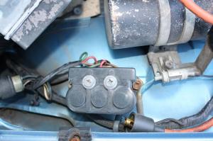
I posted this already, but something went wrong, so Ill try it again. Looking at your wiring, its very similar to mine. The blue wire with the bullet connector goes to your A/C compressors magnetic clutch. The capacitor with red overspray has two wires coming out of it. One connects to a black wire coming out of the body harness directly behind the coil. If you look in the wiring diagrams, its the last ground wire before the Check Connector plug (Mine is anyway). The other end goes to the distributor body. In the photos below you can follow them carefully through the jumble of wires around the coil. Its a noise supression capacitor for the radio. I wouldn't worry about it too much. Like Sarah already mentioned, its not on any of the wiring diagrams Ive seen and the car will run without it. It is an original piece of equipment. The wire coming out of the firewall is not original. Don't know what the last owner wnated to do with it???? Chas