


Captain Obvious
-
Joined
-
Last visited
Posts posted by Captain Obvious
-
-
1 hour ago, motorman7 said: On the rear harness there is a wire at the end of the harness near where the speaker and antenna control wires are. Haven't seen that before. Not sure what it would operate. See pic below.
I cleaned and installed the front discs and noticed slots/holes in the rim of the disc. First time I have seen that. Again, probably unique to the early cars.
And about that wire in the rear... The antenna has a ground connection on the wiring diagrams. I haven't been into that corner of an early car yet, but I thought (without actually seeing it), that antenna's ground connection came from being bolted to the body. Now that I see your harness, I suspect that ground connection to the antenna is NOT simply from connection to the body, but is in fact, a dedicated ground wire leading to the antenna.
Do you have an antenna for the car? Is there a ground lead bullet connection attached to it?
I've found several other similar issues with the factory wiring diagrams. In many locations, they didn't do a good job of conveying how grounds were connected.
And lastly... Yes, the early rotors had holes in them. Aftermarket replacements did away with that, but they are an early car thing.
-
Edited by Captain Obvious
49 minutes ago, motorman7 said: First is a Fusible link that goes to the Alternator. I have not seen that before, but apparently it is a thing on the very early cars
Yes, the early cars had a fusible between the alternator and the harness. (It's on the wiring diagram I've posted up on the site 😄) :
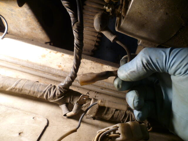
Your spade connector looks a little black and crispy. It's a high amperage connection, so it's super important that it is a good connection. Clean and tight!
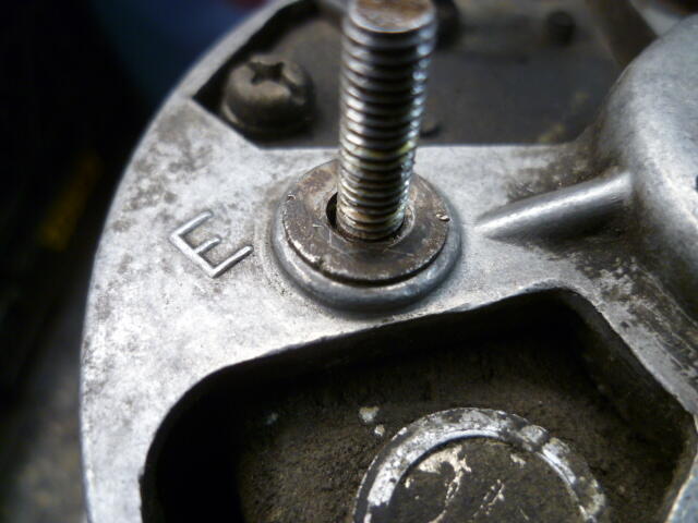
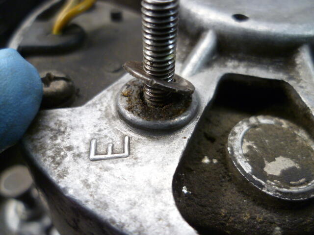
I also found corrosion underneath the washer on the ground "E" connection that resulted in about a half volt drop when I turned the headlights on. Doing the calculation, it came out to about 50 milliOhms of resistance, but 50 mOhms drops a half a volt at ten amps!! So... Clean and tight!! I can walk you through how I found that questionable connection if you want, but I doubt I would need to do that.
Here's my washer with hidden corrosion underneath:
I didn't want to put a steel washer back in there, so I made a new washer out of brass:
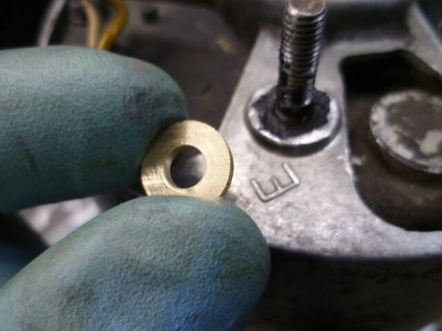 \
\-
 1
1
-
-
-
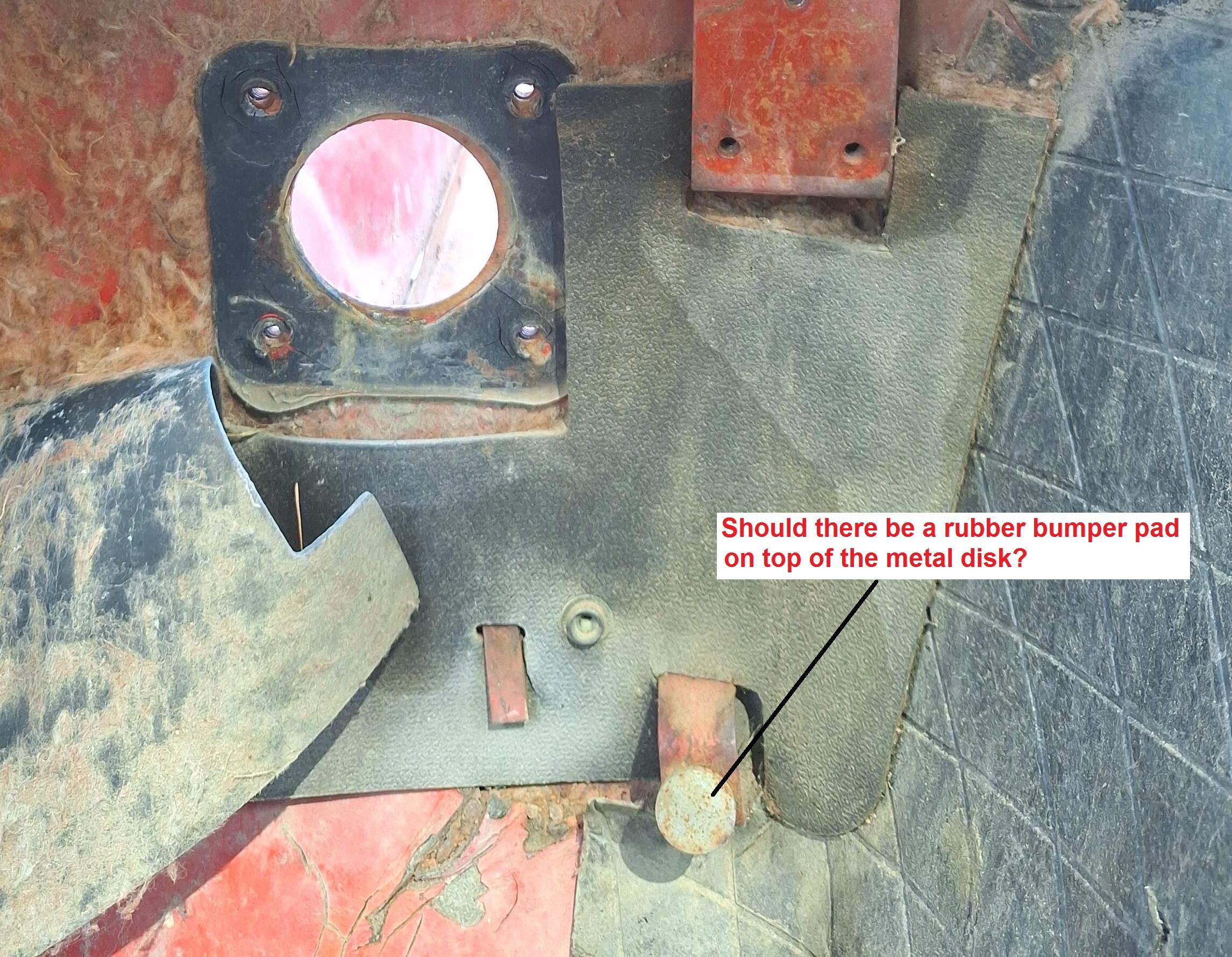
The adjustable gas pedal stop screwed into a boss on the floor.... Should there be a rubber cover over it, or is intended to be metal-to-metal?
@Parman , Your original one looks like this. Located down in the lower right of your pic:

Should there be a rubber pad on the metal disk, or is supposed to be bare?
-
23 hours ago, CanTechZ said: the $/hour rate you made is more than offset by the priceless feeling of accomplishment.
Haha!! That's what I tell myself. 😃
-
 1
1
-
-
-
7
-
-
23 hours ago, Broman said: But here's my basic question...now that I have all the small hardware cleaned and ready to send out for plating, should all my hose clamps go in the "clear zinc" box or the "yellow zinc" box?
Yes, I apologize... In true internet forum fashion, I got involved in the topic and never answered the question that was asked. And I also apologize that I do not know the answer.
I've heard that "everything in front of the firewall was yellow chromate, and everything behind the firewall was clear." Not sure if that's 100% correct, but it's more correct than not. So if that rule holds true, then your brake master clamps should be yellow.
-
-
-
-
-
8 hours ago, Zed Head said: Glad it was nine years ago instead of nine months. My memory shelf life is not terrible but not fantastic either.
Haha! I know what you mean.
But wow... Was that really NINE years ago? I've been sitting in this same spot for nine years???
-
1
-
-
So @Mike , I tried to delete the old obsolete incorrect previous version of the wiring diagram (version 6.0 on page five of this thread), and the edit privileges will not allow me to do so. I'm assuming there is a time limit on how far back in time one can go to edit something? And that post on Feb 11 has exceeded that time limit?
Can we change that? Or at least, can YOU delete it if you won't allow me to do so?
-
2
-
-
Glad to help. Hope you get some good use out of it!
Well actually, that's probably not a good sentiment, since it implies you may develop electrical issues that would warrant needing a wiring diagram. So I hope you do NOT get good use out of it! Hahaha!! 😄 In any event, I'm glad to help!
-
1
-
-
18 hours ago, Zed Head said: I just noticed that there is a resistor inline with the charge lamp. In the past I think I've seen discussions
The pics are dead (Cause photobucket sucks!!), but yeah:
-
1
-
-
21 hours ago, Zedyone_kenobi said: I then switched the Multimeter to Diode Tester. Red to black or black to red the Multimeter read OL.
20 hours ago, SteveJ said: That would indicate a failed diode to me. Wouldn't you agree, @Captain Obvious ?
Yes, that would indicate a failed to me as well. It failed open circuit.
And by the way, for educational purposes... With the new digital meters, it's pretty much impossible to check diodes integrity using the resistance scale. It needs to be on the diode check setting. If you happen to have an old ANALOG meter with a needle sweep, you can often check diodes with the resistance scale. But analog meters, like the dinosaur, are either extinct, or headed that way.
So what SHOULD you have seen? Using the diode check setting, you should have seen "OL" in one direction, and some small voltage in the other direction. Something like 0.50 to 0.80 Volts.
-
2
-
-
- Popular Post
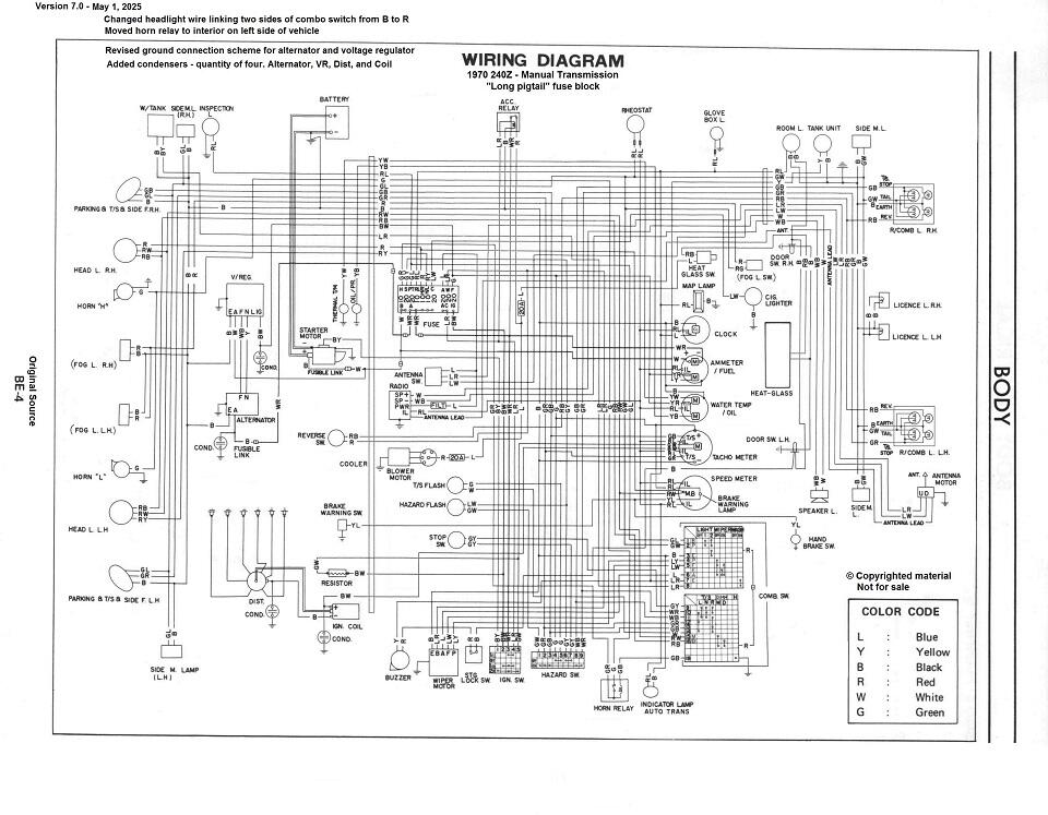
Here's the latest wiring diagram. I moved the horn relay to the interior side of the firewall. It was previously shown out in the engine compartment, but in reality it's actually located on the left side of the interior near the driver's left knee and the hood release pull. Changed the way the alternator and voltage regulators make connection to ground. And made a couple of minor wire color changes.
And lastly... Thanks to the help from the folks here, it now has condensers.
<V7.0>
-
1
-
 4
4
-
Yeah, weird. Another example of the original wiring diagram for the early cars falling short of accurate. The whole reason I started this journey! And I think I'm approaching the end. The mistakes being uncovered up are becoming less severe and less frequent.
I'll have the new rev out soon. Changes to the horn system, some power distribution stuff (grounding scheme), and of course, the condensers.
-
4
-
-
-
-
Fingers crossed! So the old dead cap either went open circuit, or shorted internally. That style of cap (known as an aluminum electrolytic) has been known to go either way. If it went short, the clock wouldn't run at all. If it went totally open, the clock might work, or might not. Sounds like yours did just that.
Hope you're good from here! Too bad about the other clock though. Probably nothing can be done with that one unless you find NOS of the xtal and/or the control chip.
-
15 hours ago, CanTechZ said: page EE-28, 29, 30. There is a circuit diagram and other info.
Thanks for the help. I have an incomplete version of the 1970 FSM, but I've been through the EE section. It don't think it shows all the condensers.
For example, the circuit diagram you posted only showed the condenser mounted on the distributor. They didn't include the one on the coil attached to the positive side (crudely grafted onto the the diagram below):
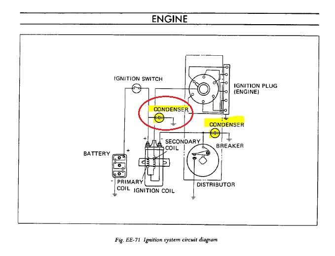
And they didn't show how the tach connects! At least not until 1972, and it was still cryptic then!
-
33 minutes ago, CanTechZ said: Hey CO, #6521 did originally have a condenser in all four locations listed above. . Here's a before & after pic. Mystery solved, Lol.
Awesome. Thanks!!
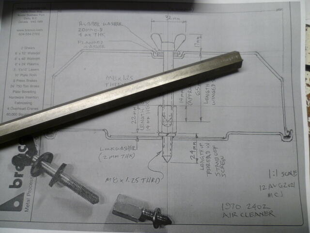
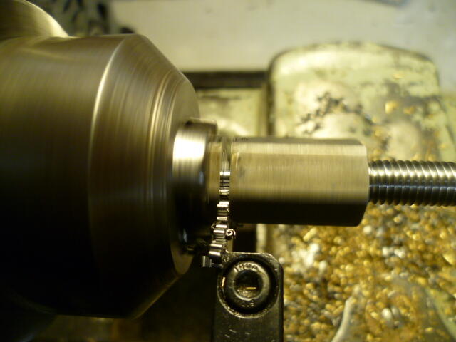
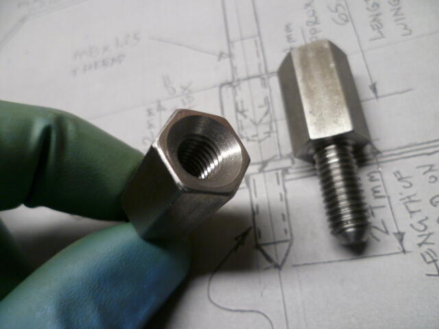
And your prolific use of pics and documentation has helped me on numerous occasions. Keep up the good work!! I'm currently working on a set of carb air cleaner attachment hardware stuff based on a sketch of yours from years ago. 😊
-
1
-
-


SN 00042 Restoration; The Older Twin
in Build Threads
And you are planning to put springs on them thangs, aren't you? Haha!!