Captain Obvious
Free Member
-
Joined
-
Last visited
Everything posted by Captain Obvious
-
 Saw a mention about having a clogged bleed nipple on a different thread: https://www.classiczcars.com/forums/topic/65237-barefootdans-280z-build/?page=7&tab=comments#comment-631700 That would give you all the symptoms you're seeing, but it would be hard to believe that a) the nipple on your freshly rebuilt caliper is clogged, and b) the nipple on your old original caliper has the exact same issue. Not saying it's impossible, but certainly unlikely? In any event, it may be worth the five minutes it would take to find out.
 -
I don't need a woman. I won't take me no wife. I got the rock and roll and that'll be my life. No page in history, baby. That I don't need. I just wanna make some eardrums bleed! Sorry... I'm back now.
-
Fingers crossed for you!!
-
Of course us on-line are limited to the descriptions of the behavior, and because of this things can get murky. At this point, you're saying you've bled all four corners and they all look great except for the right front. And at that right front, you've got a very weak stream of fluid and a pedal that still goes to the floor. Other than that, everything seems to be OK. Is that correct? One thing to keep in mind is that it really doesn't take a lot of pressure in the lines to lock up a corner (any corner) to the point where you can't turn it by hand. In other words... Just because you can't spin a rotor or a drum by hand doesn't really mean you've got normal pressure in that corner of the system. Even a small amount of hydraulic pressure in the lines is enough to prevent the corner from being able to be turned by hand. Hope your brain clearing walk-away provides some ideas and you come back shortly with the answer.
-
I looked over the pic as best I could and didn't find anything worth mentioning. Looks great! So you're thinking tomorrow might be the first start try?? What did you decide to do with the EFI temperature sensor? You running the one out the side of the head?
-
When you ran that test, where did you break into the line out at the wheel? Did the section of lines you were able to blow through include the small "S" bent hardline on the back of the caliper? Or did you split it where the flexible line meets the "S" bend metal line? Kinda running out of ideas here...
-
Cool. Hope it's as simple as a collapsed hose. And if it is... I'd replace all four of them, not just the one corner.
-
Yeah, I'd really take a real good look at that flexible hose. I don't remember if I've ever seen it specifically on a Z, but I've seen several cars where those flexible lines had closed down inside and restricted flow.
-
And by the way... what's the big picture history here? Is this something that just cropped up on a roadworthy car, or have you reached the "brake portion" of a long resurrection project?
-
Right. If you're getting reasonable flow on one side an low flow on the other, then you shouldn't be looking for an air leak. You should be looking for a restriction somewhere between the caliper and the source. I would look carefully at the flexible line from the chassis to the caliper. And I think your small leak at your pressure switch is something you need to address, but I don't think it's the cause of the big problem you're chasing.
-
Dropping back a bunch just to be sure... Did you bench bleed the replacement master cylinder(s) when you put it on? Also, you said you went to the old helper method of bleeding with no improvement. When you were underneath bleeding it old school, did you get a good stream of fluid out of the calipers when you cracked open the bleed nipple? Did that stream appear to be the same on both sides in the front?
-
I get a similar "poof" sound when I hit the brakes and they go to the floor. Although it's from me, and not the car... Sorry, I know it's "too soon", but just couldn't help myself.
-
I don't know anything about the draw-down hatch mechanisms, but I know a guy who's been working on putting in a linear actuators on his (shaved locks) 260Z. I think he's on his second, no third. Fourth maybe? revision of the project. It's not as easy as you might think. @GGRIII The doors were pretty easy. The hatch has been a PITA.
-
Understood. I was just thinking maybe you had some measured flow numbers from the two you could compare. I was thinking that could be a data point for someone looking to verify if their injectors are the right ones or not. No biggie. Again, glad you were able to help the OP get back on track!
-
No, it's fine. They sealed off the other end (the end you can't get a good look at) with a brazed on cap. Not sure why they felt like it needed to be that complex, but that's what they did.
-
-
Except water. Haha!!
-
-
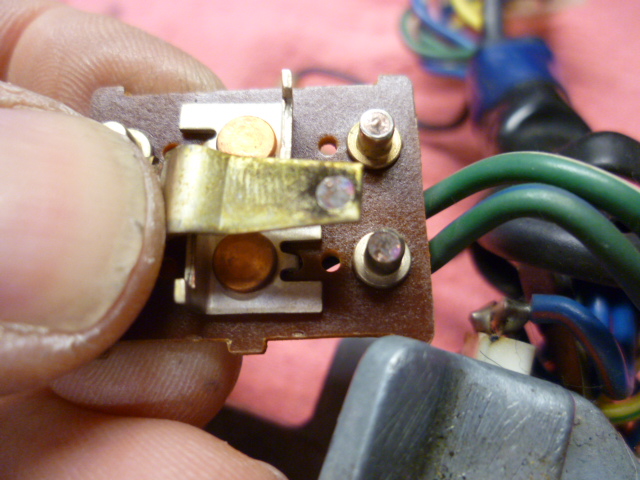
12.45V is just fine. As for keeping it cool, I suggest ice cubes. However, if you don't like the wet spots on your pants from the ice melting, you could rig up a small can of R134 and open the valve a little every now and then. Seriously though... That desoldered wire is obviously the result of a fault somewhere generating way too much heat. The issue is if you haven't figured out what the original fault was, there's the risk that it happens again. My first guess would be failing burned up switch contacts inside that switch you pictured. I don't want you to put it back together now and then just have it happen again in a couple weeks.
-
I've read on the internet that David was messing around with custom roller rockers for the L-series engines. I also read on the internet there were some reliability issues. Do you know anything about the stories? PS - And apologies to the OP for the distraction.
-
Well THAT doesn't look right! Haha! Couple thoughts. First, before you bother to reconnect that green/blue wire, have you verified that wire actually has the correct battery voltage on it? Should have 12V on it when measured to chassis ground. And second... If that wire got so hot that it desoldered itself before, do you know why? And if so, have you changed something to prevent it from getting that hot again?
-
Actually POR-15 claims to be flexible. Here's a snippet from their website: POR-15® Rust Preventive Coating is an effective anti-corrosive and rust preventive coating that offers superior chemical resistance due to its dense, cross-linked molecular composition and non-porous attributes. It has the opposite chemistry of ordinary paints. Now add to that POR-15® Rust Preventive Coating incredible hardness, toughness, and flexibility and you have a coating that is practically indestructible. Clearly they can CLAIM pretty much whatever they wish, but "flexible" did make it into their marketing pitch.
-
Gotcha. Out of curiosity, did you run the same test (using the ECU) to drive the replacement injectors before you stuck them in? Or was it just faster and easier to toss the replacements in and give it a whirl? Glad you were able to get his car running better!
-
Agreed. Maybe not quite as good as the OEM, but it's probably "good enough" either way.
-
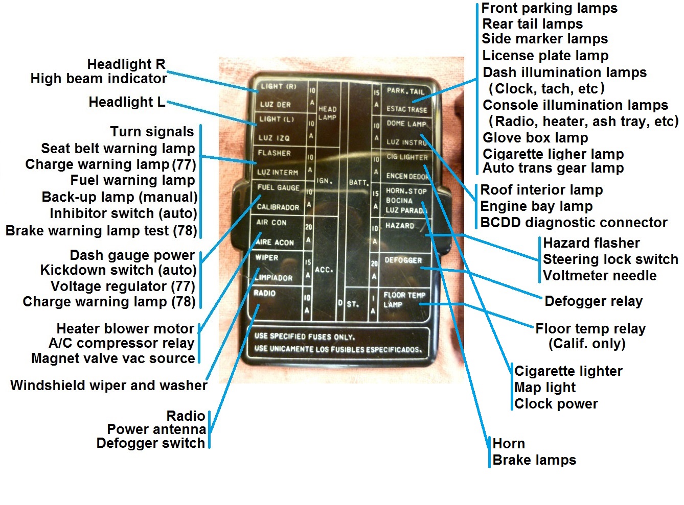
What Steve said. The GL over at the steering column should be hot at all times. If it's not, you need to move upstream towards the fuse block. And you don't need to check fuses by swapping them into other locations... You've got a meter, right? I bring that up because I can picture a scenario that goes like this: You pulled the (burned out) park/tail fuse and stuck it into the cigarette lighter position. Then you checked the brake lights and they still worked. All completely true statements, but tells you nothing about the integrity of the fuse that came out of the park/tail location. Not saying that's what happened, but simply saying it's possible. Here's a rough non-pretty layout of what fuses do what for the 77 and 78 years. Might help a little?