Zed Head
Free Member
-
Joined
-
Last visited
Everything posted by Zed Head
-
 Yes, from the contact surface on the ear. Others have determined the same 92mm number, EuroDat among them I believe. There's a thread out there somewhere.
 -
Ack. So many parts and so many possibilities. Best to remember that the throwout bearing collar height is designed to match the height of the levers it sits on in the pressure plate. Collar and pressure plate are a matched set. 92 mm (+/- an mm) from the surface of the flywheel to the surface that the fork tines ride on is the key dimension. If you have that number you will most likely be okay. I will never install a transmission again without confirming that measurement. Attached a picture, not perfect but I think it illustrates. Edit - almost had the perfect post but had times instead of tines. Carp.
-
I was going to say if that's a Rebello motor why not ask Rebello? And heat range is more about keeping the electrodes hot enough to stay clean but cool enough to avoid pre-ignition. Indirectly related to engine temperature but evaluated independently.
-
What Diseazd said. All you'll need to do is get the little half-moon facing forward, on TDC compression, instead of TDC exhaust.
-
On my 76 the knobs are rubber (black with a white stripe) and just pull straight off the metal lever end.
-
I have several exhaust manifolds, and three different heads and I've never seen a wear mark on the outer exhaust studs from the manifold touching it. The three center bolts locate the manifold and there's a pretty big gap around the outer stud holes when everything's clamped down. For the 280Z's and ZX's anyway. The stud is clamped at the top and the length of the stud is free to act as a lever on the base of the stud. I think that it just moves back and forth with every heat/cool cycle. The differential is greatest at the ends since growth is away from the clamped center section. Add in the tensile forces from clamping acting on the narrower root of the thread and it seems reasonable that the outer ones break most often. Like breaking a piece off of a coat hanger. That's my fatigue theory in a big nutshell. Someone could probably design a clamping mechanism that allows the manifold to slide under the clamping nut and washer to remove the side load. It would have to be super durable though and would probably cost a lot of money.
-
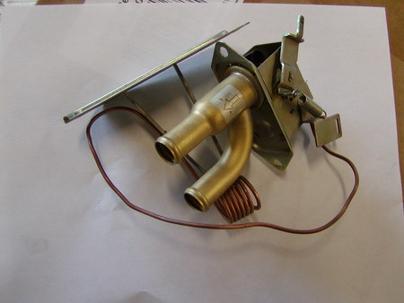
Here's what you'll be looking at. The end of the lever where the cable attaches is at the upper right.
-
I can't remember for sure, but I think that if you remove the front panel/face plate over the heater controls you can easily see the levers and cables that move the various parts. Might be easier than a mirror, although I do recommend the mirror also, I use one often. Pull the rubber knobs off of the levers, remove the screws and pull the face plate off. It's not super-difficult. If you try the mirror, make sure you have a bright light. Sit in the passenger seat and position the mirror and light and you might able to see if it's moving the watercock lever or not. My car had a bent cable which wouldn't push, and pushing is what shuts the watercock. You'll probably use the mirror and find that the lever isn't moving, then take the face plate off and find a bent cable. But Captain Obvious wrote up a whole thing on using Honda watercock valves in place of the expensive Nissan valves, if you find that the lever is moving but the water flow isn't controlled.
-
I have a slight leak at the front of my manifold and the stud is intact. I thought everything was fine when I put it together but apparently not. If the engine has been run with no stud it's almost guaranteed that exhaust gases have blown through the seal and done some damage. Odds of a good seal after the stud is fixed are low. Something to consider. It was fun to brainstorm some ideas but you'll probably be removing the manifold after whatever you try anyway. Plus the risk of doing damage to the head.
-
Seems like there were a lot of good suggestions in that thread from two months ago. A summary of what you saw there might help focus. I know I made a suggestion or two. With "focus" in mind, today's camera and laser technology would seem to give some big advantages over what was available in the past. A drilling fixture bolted to the head or manifold, a bore scope and/or laser to assure that the fixture is centered, and start drilling. With the right camera you'll get a better look at what's happening than with your bare eye. As far as leaving the broken stud, the gasket will leak and can erode the head material. Then you'll have to remove the head to have it resurfaced. My theory on why they break is fatigue. The studs get bent back and forth with every heating/cooling cycle. The ones on the ends move the farthest.
-
Check this. With the ignition timing mark on zero, and the straight (driver's) side of the chain tight.
-
It's been proposed that the warning light switch might have some sort of protective block-off function, and I used to have that in mind for a while but you can see that if that was so you'd never be able to bleed the brakes once the switch moved over. It does stop moving mechanically to allow the "good" side to build pressure. The "fix" for the switch when the light goes on is to bleed the brakes to get the pressure balance back.
-
1971 has the proportioning valve in the back. Later cars have it up front. The thing in Chickenman's Post 24 is the warning light switch. John Coffey says that they get stuck sometimes. But it doesn't meter pressure or flow, it just shows when there's a an imbalance. All described in the manuals.
-
One other benefit of PCV is that the vacuum, and the flow of fresh air through the crankcase, will purge moisture and any raw fuel from the oil. I had a clogged PCV system on my Pathfinder and milky gunk started to build up on the oil filler cap. Fixed the clog and it never came back. PCV has many positives.
-
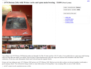
For less than $5400 you could probably get this shipped to your place - http://salem.craigslist.org/pts/5280971074.html Here's one that was mentioned recently - http://seattle.craigslist.org/kit/pts/5360307108.html $7000 seems like a lot of money for a basket-case.
-
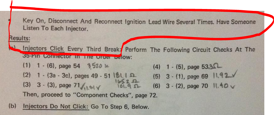
Don't replace the ECU. If you hear the injectors clicking, then it's performing its main function. The ECU's typically fail by dumping too much fuel (flooding) or none at all. But if you're injectors are clicking they are opening and closing like they're supposed to. Are you sure you're actually hearing the injectors? You should hear all six click at the same time, each time you break the power circuit. I'm going to hit on the starting fluid anomaly again. Starting fluid is a very volatile fuel, too volatile to use to drive on, but designed to get an engine spinning so that the normal control system can supply gasoline appropriately. You're not even getting a "pop" with starting fluid. You should be able to completely remove the ECU and the AFM and the throttle body and "run" the engine with starting fluid. The fact that you can't indicates a problem unrelated to the ECU and AFM's functions. They're not the cause, from what I see. The ECU and AFM only control gasoline supply, that's it. With starting fluid, you don't need gasoline, therefore you don't need the AFM and ECU. I repeated myself, to try and get this point through. You're outside of the ECU/AFM EFI system diagnostics. You have a basic engine mechanical or ignition problem. Hard to tell what it is, since you did get cylinder pressure, and you have seen spark. Here's a simple test to see if your ignition timing is close. Get the ignition timing mark at about 10 degrees, the rotor inside the distributor cap pointing at the #1 cylinder (the one at the front of the engine), and the cam lobes of that same cylinder pointing up (valves closed). All you need to do is remove the valve cover. Much cheaper than a new ECU. Also, I notice that your starting fluid contain "upper cylinder lubricant". Could be that it's old and the volatiles have been used up and you're just spraying lubricant. Who knows. Get a new can of high-power gas engine starting fluid, to be sure. You're testing looks great but there's still a basic problem. Hate to see people buy expensive parts that they don't need.
-
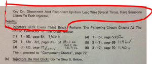
Pins 16 and 35 are ground circuits. That "point" is the one that you said was missing earlier, from siteunseen's picture, in Post #19. If you measure low resistance to the body or the battery negative cable, you're probably fine there. Funny, but there is so much information out there and so many different ways to do things that new things keep popping up. New to me anyway. You've been focused on the flashing light method, but your first picture above shows the sound method. I was aware of it but hadn't thought to mention it. Some of use use a jumper to coil negative to do the same test. Didn't know the Guide had a variant. Do you get any clicks if you try that method? I posted a copy of your copy. Also, are those your notes written by each test procedure? Looks like the harness has already been repaired, what would you do differently? Sorry to keep jumping on your posts. If someone else wants a piece of the action, please enter the fray.
-
Saw these on eBay. Somebody who wants that special green color and official A18-0000 part number may buy them. Who knows. http://www.ebay.com/itm/280Z-280ZX-FUEL-INJECTORS-NOS-NA-NON-TURBO-NEW-RARE-/271939381449?hash=item3f50d9a8c9:g:trwAAOSwDNdVss7g

-
Can't be this one - http://seattle.craigslist.org/skc/cto/5358538877.html Must be this one - http://seattle.craigslist.org/kit/pts/5360307108.html $1 price almost always means that they want too much money and are afraid to post a number. Who knows. Too bad there's not a trailer as part of the package.
-
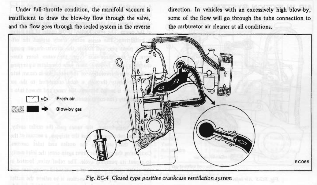
Here's what they show in the 72 FSM. They only describe the reverse flow in words here. In later FSM's I think that they added another picture with arrows showing reverse flow.

-
There's a good diagram of air/vapor flow in the Emissions chapter of the FSM's. Might give some ideas. Without the lower passageway you basically just end up a with a stagnant zone in the crankcase so the blowby byproducts will condense out into the oil. But the large diameter crankcase tube connects to a fairly small PCV valve so you're not losing as much flow volume as you might think.
-
For example, the coolant temperature sensor. If it is properly connected, and it shows .000 resistance at the 35 pin connector, that's a problem. The injector circuits have a resistance spec. also.
-
Test at the ECU connector and get real resistance numbers. The Fuel Injection Guides have great pictures of the connector pinout and test procedures in a well laid-out format. http://www.xenonzcar.com/s130/other.php Still, it should start with starter fluid...
-
FCUK = Football Club, United Kingdom. English soccer team.
-
gone = Blue? It seems like the ads load faster than usual now, and there are no autoplay noises or videos on this site, or the few other sites I visit. So, overall, not too bad. Sorry Mike but I almost never "click-through" to another site. I'm a bad user. I remember when cable TV was being promoted a "pay" service, with no commercials. Look how that turned out. Now we pay to watch commercials and suffer aggravation just to get connected. Pus, all of the cable providers are going to digital now so that they can see what we're watching. So, if you're concerned about being watched you'll need to get rid of your cable service also. Or go back to over-the-air analog signals. I think that there are still a few out there. Anybody remember UHF?