


Zed Head
Free Member
-
Joined
-
Last visited
Everything posted by Zed Head
-
 Seems like a good guess.
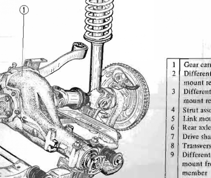
-
I would measure voltage at the alternator plug with the key On. Both should show battery voltage. You don't even need to know which is which. Unless one has no voltage. Could be that your alternator has had the L circuit shorted at the B post, to eliminate the need for one wire. That would explain why it still charges. Could also be that your three-wire is actually a one-wire. I think that ammeter only shows charge and discharge from the electrical system. No indication of voltage at all. Probably why everyone switched to voltmeters and a charge light.
-
Also. 12.2 volts is a partially charged battery. ~50% by the chart shown here - http://modernsurvivalblog.com/alternative-energy/battery-state-of-charge-chart/ Could be a part of the problem. p.s. I'm not a survivalist. That site just had the best-looking and informative chart.
-
Remembered, halfway, also, that the power that was getting interrupted with the early switches was probably coil power. Little to do with this problem. So the early/late switch comment is probably not relevant. Most of my posts in this thread have been rambly and off-topic. If the yellow wire has constant power as the instructions direct, the radio should work as expected. You might try disconnecting the solenoid wire from the starter just to see if it's the big starter current draw causing problems or a switching problem. You won't get the drop to 10.5 volts without the starter motor kicking in. Here's the Retro site for those interested. https://www.retromanufacturing.com/collections/all/1971+datsun https://www.retromanufacturing.com/pages/wiring-your-radio
-
I just did a Google on "power interrupt radio capacitor" and the first hit was some guy annoyed that his CD player was losing its spot when he started his car. So he devised a fix. Unfortunately, there's a diode involved. He didn't say what type or year of car. Hail, hail, the brain full of trivia. http://blog.iharder.net/2010/07/29/radio-how-to-keep-your-radio-on-when-you-start-your-car/
-
Google - http://forums.hybridz.org/topic/73862-tilton-light-flywheel-for-l-series/ Probably need to clean yours to see any engraving or markings. https://www.google.com/search?q=tilton+flywheel+nissan&biw=1280&bih=895&site=webhp&source=lnms&tbm=isch&sa=X&ved=0ahUKEwjg86PF6uTLAhVB8mMKHR_VBpoQ_AUICCgD John Coffey may have seen one of these before - http://zhome.com/Racing/Auto/Coffey.htm
-
A thought - maybe a branch from the Start power wire to the radio would maintain its memory. It can't draw much. If it does, you could use a relay. You could have have Acc, On and Start all wired to the radio power. Use diodes to prevent backfeed. Still think a good unit has better power supply control. Which I think is what you're originally suggesting anyway.
-
Pretty sure I've read comments in the past about the 240Z's having a momentary loss of power at the ignition switch, due to its design. The contacts don't overlap. Might have been on a Megasquirt forum, or about Megasquirt. I thought it was SteveJ that said so. Also thought it was between On and Start, not Acc and On. It changed in later ignition switches, apparently, I think that the 280Z's don't have the problem. I wonder if some sort of capacitor or uninterruptable power supply could be used to fix it. I've noticed that my combo CD player/radio in the garage takes a couple of seconds to die when I cut its power. It must have something inside that holds some power for a while. Spell check suggests "unintelligible" for "uninterubtible".
-
Just to followup - almost everybody has looked for an easy, inexpensive way to get limited slip in their Z, R200's included. Nothing has been found yet. Numerous Franken-axles, adapters, and flange swap shave been devised and tried. Even what looks like the most straight-forward and easy swap of an R200 from a 300ZX turbo has axle length problems. Nobody has come up with the sub-$1000 LSD setup yet. There is a guy on Hybridz though, who's helping a company develop an R200 LSD that should swap directly in to an R200 case and use R200 axles. Unclear what they'll cost in the long run, but the first batch is going for $700. Worth keeping track of. Maybe you can talk him in to doing the same for the R180. At least the invisible hand is doing its thing. http://forums.hybridz.org/topic/121007-mfactory-r200-lsd/
-
Depends on how it's mounted.
-
You can't even swap ring and pinion within the Nissan family, from old to newer - " In addition to the bolt in axle issues, there is another difference between early and late R180s. Early R180's measure 110mm inside the ring gear. 77 and later model year R180s measure 115mm inside the ring gear. This minor change means that the ring and pinions won't swap between the early and later models. If you have an early diff you must use an early carrier, and if you have the later diff you must use a later carrier. It is possible to use a early carrier on a later ring gear with a spacer, but that is outside the scope of this thread. " http://forums.hybridz.org/topic/49194-differential-cv-lsd-hp-torque-r160-r180-r200-r230-diff-mount/ Here's John C's first prototype shaft thread. It has comments specific to the different spline count - http://forums.hybridz.org/topic/78123-subaru-wrx-sti-r180-side-axles/ Here's one of the early Subaru diff swaps - http://forums.hybridz.org/topic/73182-subaru-sti-r180-differential-and-axle-conversion-revised/
-
The sleeves are out there - http://www.amazon.com/s/ref=nb_sb_noss/176-5899364-2390852?url=search-alias%3Dautomotive&field-keywords=Sleeves+Capsule+for+Valve+Stem+
You should specify year of car. 75-77 280Z's had a contact in the AFM to run the fuel pump relay. Also, people often open the AFM but don't adjust it, for cleaning and examination. If the glue blobs are intact it's probably OK. And, there are many symptoms that look like AFM but aren't. MSA summarized them nicely. Read the text at the bottom - http://www.thezstore.com/page/TZS/PROD/11-3040
Some of the "chatter" marks look more like chatter from a regrinding operation. Check lash after a few hundred miles, and then a few thousand. If a lobe is going bad, it will show up. One thing that might be informative on the cam lobes though, pertaining to the valves, is if there is wear on the base circle. If lash is set right the base circle will get a coating of brown, since the anti-rattle springs are lifting the rocker pad from the cam and there's a gap there (the lash). If there's wear on the lobe base, there's a chance the valve seats have worn, or a valve stayed open and got "burned" or warped. Really though, if it sounds good and runs well, you might as well just get another head ready to swap on.
I'd actually looked through the Hybridz thread before but how they fit didn't really sink in (or I forgot). Didn't really think of the rear transverse-oriented sub frame (where the BD rails terminate and weld on) as the rear sub frame. I've been looking at the arched piece that goes over the axles, thinking in terms of a lengthwise frame rail, trying to connect two parallel rails in my head. The rails should probably actually be called bracing, or stiffening ribs, or boxed sections, or boxed bracing. The metalwork in front, where the engine bolts in, would be a sub-frame. I think. The 240Z rear "rail" might better be called a rail (brace) extension. History prevails though. Found another good BD rails thread, describing how to make them fit and weld them in. http://forums.hybridz.org/topic/58497-installing-bad-dog-frame-rails/ I'm almost disappointed that I have a 280Z, with decent shape rails/boxed braces. No good reason to modify yet. Nissan shows where all of the sub-framework is in their Body chapter, as dotted lines. Here's 1972.
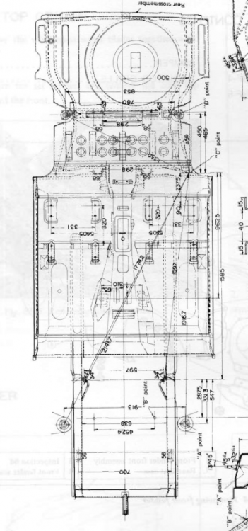 Eyeballed my 280Z and the rear and front sub-frames aren't on the same line. Not connected directly either, except through the bend of the floor pan (the bend would add rigidity), although almost overlapping. The Bad Dog 240Z rear frame "connectors" would get someone close but I don't that they're a full direct connection. It's an interesting engineering problem, load distribution/transfer, stress risers, and all that.
That's probably the part. Don't know why he calls them rear rails. He mentions connecting in the description. Apparently the 280Z sub-frames extend further than 240Z (edit - they don't, they're the same length. The 280Z's just use thicker steel and are better braced in general), so maybe not as necessary. OR maybe they're already connected. To the garage... " New 70-73 Datsun 240Z replacement under floor frame rails. Replace those rusty frame rails with these custom fabricated rails. These are two piece assemblies that connect the front frame rail section to the rear frame rail behind the seat. Great for high HP or V8 conversion "
I'm just pointing out that Bad Dog does not appear to provide the solution that John Coffey, professional race car builder, suggested was the second best bang-for-the-buck. That's all, not even debating whether it's truly worth doing or not, just saying that there's no sub-frame connector offered by Bad Dog. I seem to recall seeing the actual connectors on Bad Dog's site in the past, but maybe he doesn't make them anymore. gnosez (Gino says?) is Bad Dog. I'll send him a message and maybe he'll get in here. He already replied on the windshield question. Edit - Sent him a message, let's see what happens.
Sorry, can't get rid of this box, even after starting over. Once you put something in a Reply box it seems to be "cookied" forever. Anyway, the Bad Dog rails don't connect the sub-frames, which is what the goal was I thought. Just looking for the connectors connection.
Does he still? He only shows replacement rails on his web site. http://baddogparts.com/ http://baddogparts.com/index.php?main_page=index&cPath=2_5
Here's what made me think of CaliforniaDatsun. Some of his lobes ran right off the end of the pads.
Didn't mean to imply that you have a bad engine. Could be that somebody just assumed that the lash pads they had were right for the cam. Or they replaced the cam and used the old pads. Looks like they just didn't do the final check. Although, some people will run on the inside of the wear pad to get a little bit more lift at the valves, but yours look like on the razor's edge, not the racer's. Anyway, good that you caught it before real damage was done. Carry on...
Forgot to say, one of the main weaknesses with the Pertronix system (not bashing, just pointing out [obscure pun!]), compared to other electronic options, is that it doesn't do current-limiting. That's why you have to balance the coil and ballast, and I think it's why the tachs often don't work right. The tach is expecting a certain quantity of current. That's what the game is, finding that quantity. I think.
Actually, in your case, looking back at your specs. I don't know if my suggestion offers anything. Running the extra line to coil positive will reduce current through your tachometer trigger loop. Seems like you need more current, or an extra loop (but I don't know for sure). If my guess is right, the extra line will make your problem worse. It will drop current on the tachometer circuit. Shouldn't hurt anything though, it still runs power through the coil and Pertronix module. I might connect the line first and see if the problem gets worse. The tach might quit working completely due to low current. If it does, that would imply that you need less overall resistance, maybe a lower resistance coil. If the tach works better that's a clue that it was over-currented at high RPM. Maybe overheating. A way to run more current through the tach loop is to use a lower ohm coil. That would be on the same path as an extra loop on the tachometer. Might be a worthwhile experiment. The Pertronix situation is interesting because with the ballast and tach in series as they recommend, the overall resistance is higher than just the coil resistance. So they recommend a 3 ohm system but don't really address the ballast and tach effect. Ponder the ways to increase or decrease current through the tachometer circuit. It's hard to get a complete logic path to a solution because you don't know how much resistance the Pertronix module has when grounded, plus the ballast resistor is actually a variable resistance device. It heats up at low RPM since dwell time is longer. SteveJ probably has the answers and could critique my suggestions. He's a tach guy. Short answer is "I don't know", I'm just brainstorming.
Eyeballed my 280Z and the rear and front sub-frames aren't on the same line. Not connected directly either, except through the bend of the floor pan (the bend would add rigidity), although almost overlapping. The Bad Dog 240Z rear frame "connectors" would get someone close but I don't that they're a full direct connection. It's an interesting engineering problem, load distribution/transfer, stress risers, and all that.
That's probably the part. Don't know why he calls them rear rails. He mentions connecting in the description. Apparently the 280Z sub-frames extend further than 240Z (edit - they don't, they're the same length. The 280Z's just use thicker steel and are better braced in general), so maybe not as necessary. OR maybe they're already connected. To the garage... " New 70-73 Datsun 240Z replacement under floor frame rails. Replace those rusty frame rails with these custom fabricated rails. These are two piece assemblies that connect the front frame rail section to the rear frame rail behind the seat. Great for high HP or V8 conversion "
I'm just pointing out that Bad Dog does not appear to provide the solution that John Coffey, professional race car builder, suggested was the second best bang-for-the-buck. That's all, not even debating whether it's truly worth doing or not, just saying that there's no sub-frame connector offered by Bad Dog. I seem to recall seeing the actual connectors on Bad Dog's site in the past, but maybe he doesn't make them anymore. gnosez (Gino says?) is Bad Dog. I'll send him a message and maybe he'll get in here. He already replied on the windshield question. Edit - Sent him a message, let's see what happens.
Sorry, can't get rid of this box, even after starting over. Once you put something in a Reply box it seems to be "cookied" forever. Anyway, the Bad Dog rails don't connect the sub-frames, which is what the goal was I thought. Just looking for the connectors connection.
Does he still? He only shows replacement rails on his web site. http://baddogparts.com/ http://baddogparts.com/index.php?main_page=index&cPath=2_5
Here's what made me think of CaliforniaDatsun. Some of his lobes ran right off the end of the pads.
Didn't mean to imply that you have a bad engine. Could be that somebody just assumed that the lash pads they had were right for the cam. Or they replaced the cam and used the old pads. Looks like they just didn't do the final check. Although, some people will run on the inside of the wear pad to get a little bit more lift at the valves, but yours look like on the razor's edge, not the racer's. Anyway, good that you caught it before real damage was done. Carry on...
Forgot to say, one of the main weaknesses with the Pertronix system (not bashing, just pointing out [obscure pun!]), compared to other electronic options, is that it doesn't do current-limiting. That's why you have to balance the coil and ballast, and I think it's why the tachs often don't work right. The tach is expecting a certain quantity of current. That's what the game is, finding that quantity. I think.
Actually, in your case, looking back at your specs. I don't know if my suggestion offers anything. Running the extra line to coil positive will reduce current through your tachometer trigger loop. Seems like you need more current, or an extra loop (but I don't know for sure). If my guess is right, the extra line will make your problem worse. It will drop current on the tachometer circuit. Shouldn't hurt anything though, it still runs power through the coil and Pertronix module. I might connect the line first and see if the problem gets worse. The tach might quit working completely due to low current. If it does, that would imply that you need less overall resistance, maybe a lower resistance coil. If the tach works better that's a clue that it was over-currented at high RPM. Maybe overheating. A way to run more current through the tach loop is to use a lower ohm coil. That would be on the same path as an extra loop on the tachometer. Might be a worthwhile experiment. The Pertronix situation is interesting because with the ballast and tach in series as they recommend, the overall resistance is higher than just the coil resistance. So they recommend a 3 ohm system but don't really address the ballast and tach effect. Ponder the ways to increase or decrease current through the tachometer circuit. It's hard to get a complete logic path to a solution because you don't know how much resistance the Pertronix module has when grounded, plus the ballast resistor is actually a variable resistance device. It heats up at low RPM since dwell time is longer. SteveJ probably has the answers and could critique my suggestions. He's a tach guy. Short answer is "I don't know", I'm just brainstorming.


Important Information
By using this site, you agree to our Privacy Policy and Guidelines. We have placed cookies on your device to help make this website better. You can adjust your cookie settings, otherwise we'll assume you're okay to continue.