Zed Head
Free Member
-
Joined
-
Last visited
Everything posted by Zed Head
-
 They are fairly easy to twist out of the top of the diff. You might go to a local wrecking yard with a pair of pliers. Don't squeeze too hard if it's a plastic one. I think that the later Zxs came with metal. Maximas and maybe Subarus might use the same went.
 -
The ECU holds the injectors open longer as the AFM vane opens farther. With a vacuum leak less air flows past the AFM, the vane doesn't open as far, so the injector open time is shorter, giving a leaner mixture. The ECU also takes information from the temperature sensors and the tachometer. The Engine Fuel section in the FSM describes it all, with graphics. Fuel pressure can affect the mixture also. Have you checked your fuel pressure and fuel pressure regulator? When mine went bad, the engine ran very rich.
-
The Zs don't have a donut gasket like chevy's do, they just have a plain old flat two port gasket at the exhaust header/manifold junction. A leaky gasket really shouldn't affect cold running or crappy power-making. Changing the intake/exhaust gasket probably won't help your problem. If you do decide to do it anyway, you'll probably break a bolt or two on the thermostat housing and a stud or three on the intake/exhaust system. Search ez-out, tapping, broken stud, etc. before you start to know what you're heading for. From my own experience and what I've read, you will break at least one stud in the head and have to put extra effort in to getting it our before you'll be able to finish the job. A vacuum leak would cause it to run lean. Extra resistance in your water temperature sensor circuit would cause it to run rich, one among several rich-running possibilities.
-
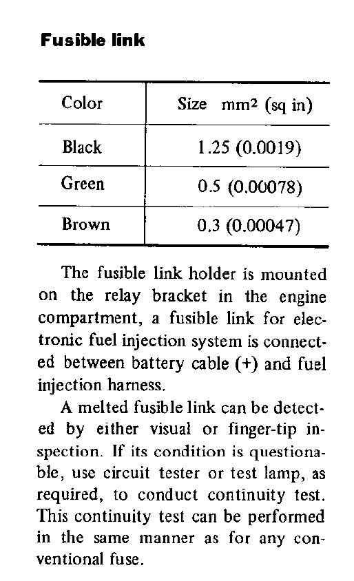
The real question is not about color but about amperage rating. Is 0.3 mm ^2 a typo also (the size of the "brown" link used for the headlight and other circuits)? Would the headlights draw more amps than the fuel injection harness - green 0.5 mm^2 link? Courtesy Nissan sells a red fusible link that is 0.3 mm^2 in size, which would be a lower amperage rating than the green link. But the altlanticz page says that red is a larger size and higher amperage rating (0.69 mm^2 - 50 amps) than green (0.5 mm^2 - 40 amps). The Datsun store doesn't tell the size or the amp rating of their red link. As I said, it probably matters little in function. I'm just trying to understand where the idea came from, that those red (or Br) links should be replaced with 50 amp maxi-fuses or similar.
-
If you search transmission swap, 240Z, or 280Z on Google, this forum and other forums you will find a lot of good reading. This topic comes up all of the time and there are several good write-ups around the internet. The 2+2 probably has the 240mm clutch and flywheel, and your 260Z has a 225 mm setup. So you would need to move the flywheel over also.
-
Do you have the vacuum advance hooked up to full manifold vacuum instead of ported? That would give you an extra 10 - 18 degrees of advance at idle and increase your idle speed.
-
I can't remember if the vacuum switch solenoid is normally powered or not. Just make sure that the disconnected wire or plug doesn't have power to cause a short in the future. Always a good idea to test disconnected plugs for power and cap them off if they do. I see that you found the BCDD. There should be a black wire coming out of it to connect the yellow wire to.
-
-
I would just connect a ported vacuum source to the distributor for vacuum advance all the time for peppier engine response and gas mileage, connect the BCDD wire to avoid backfiring and stinky exhaust when decelerating in gear, and trace out the wire to your water temp sender using the 1976 diagram. That should be all that you need to get back running well. Edit - and the water temperature sensor of course, but I think its wire comes from the main FI harness.
-
With a wiring diagram you should be able to determine where those three wires connect. Saridout made up a full color PDF diagram for 1976, search his name on this site if you don't have it already. The vacuum switch solenoid allows vacuum to the vacuum advance canister on the distributor in fourth gear only. It seems to be for emissions, apparently advanced timing is dirtier than retarded. I bypassed mine so I get vacuum advance in all gears (we run E10 in Oregon so I figure I'm breaking even on pollution). The BCDD is that weird looking thing on the bottom of the throttle body,with the rubber cap. The yellow wire supplies power to a solenoid when the ECU tells it to. The water temp switch (not sensor) tells the ignition module when to use the other pickup in the distributor to advance timing by ~6 degrees. This appears to be to keep the idle speed up when cold. When the engine gets warm it switches back the the retarded pickup. I don't have the stock module so I don't use the switch anymore. In between the time that the AAR closes and the engine gets up to full temperature I will get a pretty low idle sometimes. If you still have the stock ignition module (I don't) and 4 speed transmission, with fourth gear switch (mine's gone), and distributor with two pickup coils (I'm down to one pickup myself), you could get yours to work correctly.
-
The yellow wire goes to the BCDD. The plug that you have labeled Harness 1 plugs in to a another plug with a red, white and yellow wire that appear to go up to the sensors in the thermostat housing. On my car that condenser plug connects to a black wire that is grounded to a distributor mounting bolt. My car does not appear to have been messed with much, but I'm not sure why Datsun felt the need for a separate long wire all the way to that point, but that's where it goes.
-
The attached picture of page BE-6 from the 1976 FSM shows where the Br (Brown) came from. Notice that it is also the smallest gauge of the three. If your fusible link block has not been too damaged or worn out, there will be a label on the side designating Bl and Br as the fusible link colors. Somewhere over time brown became red or maybe the factory links never did come out brown in color to match the FSM. That may be how a 0.3 square mm brown link turned in to a thicker red link. Color didn't match gauge and someone went with the color code for replacement. In the big scheme the safety margin that most engineers use probably makes it irrelevant. It's just interesting how some information gets a little warped and propagates.

-
The insert is basically an internal shock absorber. You should be able to press the shaft down in to the body like you would a normal shock absorber. Even the gas-charged ones only have low gas pressure and can still be worked up and down, the gas pressure will slowly push the shaft back out of the body after pressing in. I don't think it should move side to side at all. If might help if you defined "slightly". 1/16, 1/8, 1/4"?
-
Blue, I'm curious - all signs point to your page with and Wayne Monteath as responsible for propagating the notion that what should be 30 amp links are actually 50 amp. From your page - (Thanks to Wayne Monteath for uncovering this rare table!). Who is Wayne Monteath and how did he determine that the Factory Service Manuals are incorrect? Where did the "rare table" come from? Honest curiosity. I have only seen the Brown = Red = 50 amp link on the atlanticz site. No where else. Thanks for any insight you can offer.
-
The red circle is a bypassed heater core. The common leak point is the control valve, just on the other side of the firewall where those hoses used to go. The blue circle is the throttle dash pot, to keep the throttle blade from slamming shut when you let off the gas. It doesn't take a vacuum line, it just looks like it does. The hole is just an outlet for air to pass in and out of as the diaphragm inside moves. Must be a car you just picked up and it doesn't run? Why are you removing the engine?
-
1976 has a Brown (Br) link that estimates out to about 30 amps, based on gauge (color and gauge shown in the FSM) and interpolated between the other "known" links. Red seems to be the popular replacement for Brown, but there appear to be two versions of the Red links, the ~30 amp, which you would get from Courtesy for example, and a 50 amp which others sell. There does not appear to be any supporting documentation for Brown = Red = 50 amps, but it's out there. Be careful with any fuse swaps you do.
-
Most important is what the wire does, when the car is being used. I would check if it's grounded first, using an ohm-meter. Maybe it shorted in the past and has been bypassed. Then see if it is powered at the different key positions, using a test light or a voltmeter. That information will give you more clues about where it should be or was. Edit - Don't connect it to anything until you know what it does. You could cause a short and burn some fuses, fusible links or wiring if it gets power during operation.
-
For 1981 the FSM shows a CR of 8.8 for the NA engine versus 7.4 for the turbo engine. The earlier N42 blocks (with stock pistons), and N42 or N47 heads, ran 8.3 CR, no turbos, EFI.
-
You might be lucky that your order didn't go through. Apparently the owner has not been very responsive in the recent past. Read through this thread for reference - http://forums.hybridz.org/index.php/topic/62367-anyone-heard-from-ross-modern-motorsports-lately/page__pid__934028__st__120#entry934028
-
Are you sure that you're not feeling the benefits of an extra 9 degrees of advance? That would be noticeable by seat-of-the-pants. There is no reason for your timing to change with the new module. The E12-80s don't have any timing control like some later ignition modules do.
-
I've seen it recommended that it's better to block off the water hoses than to bypass them. Search "heater" and "cooling" on Hybridz. Best guesses on the hoses - 1. Ported vacuum from the throttle body - distributor vacuum advance and ?? 2. Same. 3. Charcoal canister 4. AC control reservoir 5 or 6 - Brake booster, can't see the picture clearly. All memory and guesses but I think they make sense. When you get the engine in the car it will be more clear.
-
The screw on the side of the AFM only adds air to the idle mixture. It can give a little smoother idle (in my experience) but at the expense of running richer at idle (and failing emissions testing in Oregon). It will have no noticeable effect on any driving conditions, only engine idle. The most common cause of running rich on these early EFI systems is extra resistance in the water temperature circuit (or CHTS for later models, but your 78 has a water temp. sensor), usually from dirty connections. You can check the whole circuit at the ECU plug - measure resistance there and compare the reading to the table in the FSM to see if you're getting the proper resistance at the ECU for the temperature. The simplest is to measure at ambient temperature to see if you're in the right range. Just trying to save you some time. Don't spend too much effort looking at the screw on the AFM. Congrats on getting back on the road...
-
You might try isolating the calipers from the lines to see if you can find where the problem lies. If you still have the wheel cylinders from the drum brakes, put them back on and clamp the piston in the bore (vise-grips, wire warp, zip-tie, etc.) so you can build pressure. Orient them so that they can be bled. If you can build pressure then the problem is in the calipers, if you can't it's in the lines or MC. It will take a little time, but certainly not another five hours. If you isolate it to the calipers, reconnect one at a time to see if it's one or both of them. You should be able to do this without removing the calipers, just the brake lines. There might still be air in the lines, you just need to find where it's hiding. Maybe there's a casting flaw in a caliper, holding an air pocket. I also know that the dust seal on the caliper piston is designed to push the brake pad off of the disc to keep it from rubbing. Maybe you have some other spring-loaded piece pushing the piston back. Can you eye-ball the piston as you let the brake pedal up, after pumping it up to pressure? If it moves back in the bore a lot, it will be pushing fluid back the the MC. It should barely move. Just a few thoughts to isolate the problem to a distinct component.
-
It's still odd that only three cylinders were affected by the breakthrough in to the EGR channel. All six intake runners are exposed to the channel so all six should have had excess exhaust gas coming in. The EGR ports in to the runners of your intake manifold might be messed up also. If your band-aid fix is to disable the EGR entirely, you'll probably get back to balanced running, but it might be worth checking the individual EGR ports, if you can get the plugs out. I've never seen one myself so don't really know how much gas they flow.
-
That's for sure a new one. Have to remember this for future people with "low intake vacuum" problems. I wonder how many other corroded EGRs are out there. I got curious and just went out to the garage to take apart a 1978 parts intake I have. The EGR channel was totally choked full of caked carbon residue. Interesting that your was the opposite and apparently still letting exhaust gas through, although in excess.