zKars
 Subscriber
-
Joined
-
Last visited
Everything posted by zKars
-
 Z's don't have a good place to put a control pod like that underdash. I certainly would not try to attached it to foam dash material. I'd put it where the stock controls are above the radio. remove the stock control mechanism from the back of the heater control panel, then cut out a rectangle, create and mount a flat plate in the hole, then mount those four controls into that panel. Each one comes out of the VA panel. Take the knobs off, you'll see how they mount. I respect your attempt to install Vintage Air in your Z given your multiple posts that suggest this process is a challange for you. I've done several, and they all take a huge amount of time and detail as EVERYTHING has to be created from scratch or fabricated into place. There is no "best way" to any of it, you just have to look at what you have and try to each step best you can. All the best in your efforts.
 -
The lock/wedge pin provides a critical function, at least from the original design point of view. It has to do with how the rubber bushings are designed to work. They are designed to have their center tube locked, and the suspension motion flexes/twists the rubber to provide movement and isolation. The joint is not intended to be free to "rotate". The center pin thus has to be locked in position so that the pin stays locked with respect to the center tube of the bushing. Same for the inner control arm bushings. This is why the FSM has you torque them to final spec with the car at ride height, not with the wheels dangling off the ground. You want the neutral point (locked with no twist or torque) of the bushing to be in the center of the suspension travel so the bushing can flex either way without exceeding its elastic limits. Now that said, little harm is done if it all does rotate. What makes me the most nervous is the possible tendency of the nuts to back off since they are both RH thread with you let the pin rotate with respect to the bushing. I know it hasn't happened to anyone yet, but....
-
It's worth mentioning that there is no one tool that will remove all spindle pins. Sometimes they are more stuck than the strength of the puller materials can handle. This is unfortunately more common than I care to think about. I humbly refer you to a reference post on hybridz where we discussed the various spindle pin removal difficulty "levels". Gives us a reference point and common language. http://forums.hybridz.org/topic/122593-spindle-pin-club/
-
oh boy.... Well you can start by turning the idle speed adjust screws out to reduce idle speed. Each carb has a screw that touches the linkage, (left side of front carb, right side of back carb), and there the high speed idle screw up on top by the throttle rod top ball that you might have inadvertantly used to set the idle. Back it off so it does not touch the Crazy idle speeds can also be a large vacuum leak (carb to manifold or manifold to head, or some hole left open on the balance tube or intake... The way it suddenly when "bang" then started to smoke makes me a bit nervous....
-
Sure looks like a Japanese version of a El Camino/Ranchero ! Quite pretty
-
Hood release on the side, vent knobs hang from the dash mount brackets. You'll see two holes where pointy ended screws go in the bracket.
-
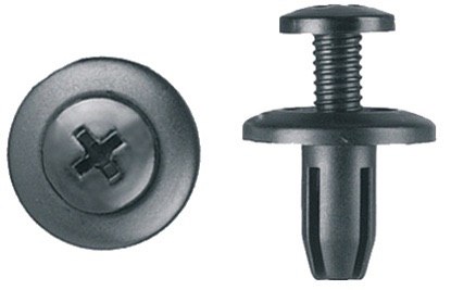
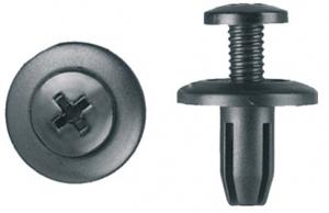
These might be an option. Fits a 6 mm hole and appears very easily removed and re-usable, 5mm holes can be made into 6mm holes pretty easily. http://www.clipsandfasteners.com/Push_Type_Retainer_Honda_Isuzu_Nissan_p/pas1597-25.htm I've gone to the trouble of replacing all my interior plastic rivets with 10-24 insert nuts and matching wide head black machine screws. Tight, squeak free, and totally removable.
-
Ohhhh! good reason to fire up the lathe! I'll make a set and give this a shot. Never spun anything that wasn't axially balanced. Fun!
-
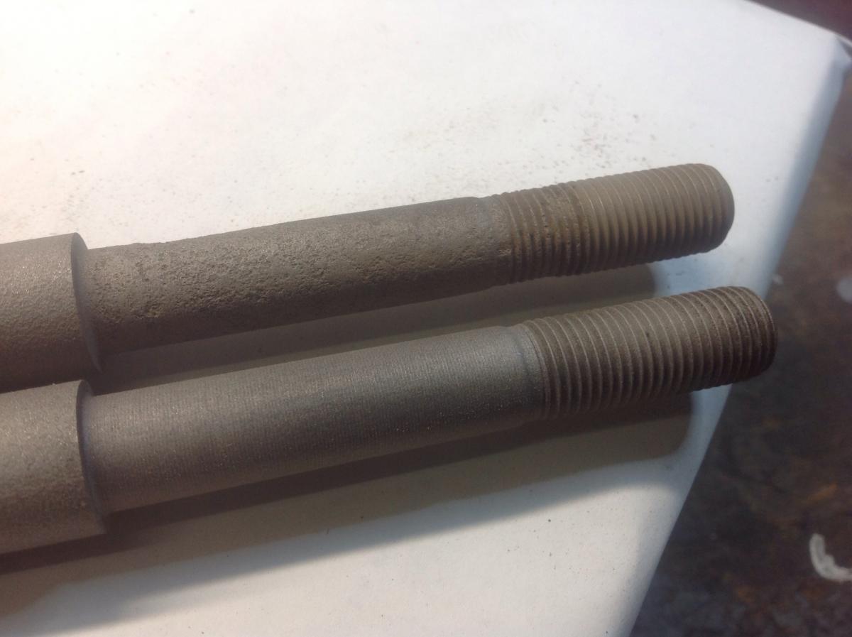
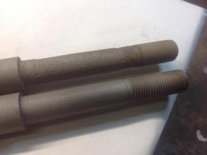
And in the never ending quest to add value to a topic... I had a pair of set of T/C rods from a 77 that were sitting 6 ft away from me as I was doing mine the other day. Of course, I had kept the bushings and washers on there to keep it all together until I had a chance to put them away, and there were the washers just glaring at me in the proper convex to bushing orientation. Did I see that? No, of course not. Anyway... on to the real reason I'm posting this time! The following pictures shows the threaded end and step area of the two spare rods after a quick sand blast for inspection. Which one would you keep and which one is scrap metal? Same car. Scary, huh?
-
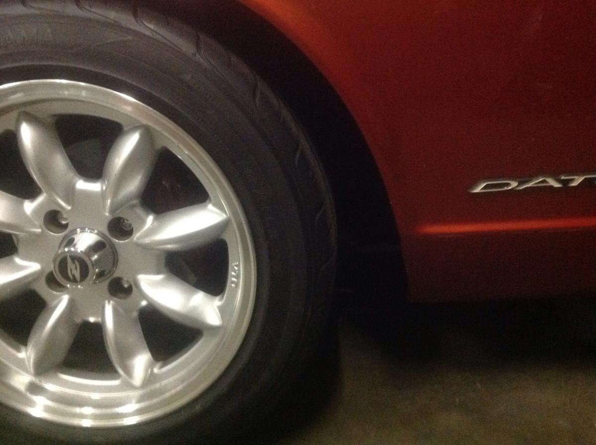
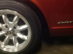
Progress. Well, some. After re-reading and staring at your pictures above, I realized I put the big washers on backwards.Convex toward the bushing faces, not away from. Duh! I tore the T/C rods off and switched them. I also put poly bushing on the back (I know I know) to try to get a little less length due to the offset compression of the bushings. Couple observations. The manor in which the bushings squish is quite different with the washers in the convex to bushing orientation. With the poly on the back, when tightened fully to inner tube contact, the front rubber bushing has squished less (more remaining thickness) then when its washer was concave toward it. Hadn't expected that, but it's true. Other than the rumors of pending T/C failure now, there is clearly ample rubber bushing in front to allow all the TC rod movement I'd ever want or need in any direction without binding or fear or causing undu stress on the rod if the suspension droops or compresses to maximum. My wheel now sits about a 1/2 further back in the wheel well. Turning now does not rub. I also rolled the valence edge a bit further and trimmed the end of the BRE spoiler to give just a bit more room. One could also loosen the valence mounting bolts and slide it forward a bit to gain a wee bit more room. This idea came from some 'guy' in a PM on the topic, excellent advice I might add...
-
Thanks for the input guys, as always, and even CO's desparate and appreciated attempt to point out even the most unlikely assembly option. I've been known to do sillier things. I did in fact use both bolt holes in the control arm. hmmm to fix this, I could put only the back T/C rod hole in the front control arm hole ... ;0 Blue I'm not sure putting the control arms on the wrong side to put the bushing offset to the rear will not help move the wheel back. The T/C rod length determines the wheel fore/aft position so I think you'd only put the control bushing in a nasty out-of-square cramped position and skew the control arm. I realize we are mostly concerned with the bushing joints rotation (up down) stiffness, not the back/front motion, which only happens (and is small) during changes in rod compression or tension, which are transient and only happen when going over bumps or hard braking etc, but its the static position (parked) and resulting length difference that is definitely affected depending on which bushing pair you use. P|R, P|P, R|P or R|R. Same on both will self center the bushings on the frame pocket hole, (stock length), poly front make the effective rod length longer (frame pocket to front hole of T/C rod), poly in back makes it shorter. Well, I'm not putting poly in front, its going to make the rod static length even longer and make my issue worse. Time to trim the valance maybe. I'm not changing tires again!
-
Thanks for the confirmation pictures, I'm now sure I have it assembled correctly. I'm running 16x8 rims, +5mm offset, tires fit perfectly inside the top of the wheel well. Not like they're sticking out or anything that would make this tire rub situation worse. This poly on one side thing is bugging me. I can see reasons why you might want it one either side, depending on whether you are trying to dampen compression loads, like when dropping a wheel in a hole or rut, or when you are trying to reduce caster changes due to steering and damping loads where you might convince yourself to put it in front or the back, or both. My objective is the former, hence my choice of rubber in front. Now when I look at your pics of the bushings with the second locknut, I see rubber bush in the back is not very compressed. This is very different from experience when I put my rubber in front/poly in back. The rubber went damn near flat before I reached lockup length. I'm wondering if you don't have the unit compressed enough to lock the big washers against the center tube (lockup length, like the rear wheel bearings against the distance piece). That would contribute to the nut backoff problem you're having. Also don't re-use an old nylock or crimp nut. I can also see an issue with using one poly one rubber in terms of the relative centering of the bushings and the resulting effective length of the T/C rod. Poly in front biases the rod too long, poly in back makes it effectively too short. It's only "right" when you have the same bushing on both sides. You can use this to your advantage, or you can cause caster problems. I might just be putting that poly bushing back in the back and pull that wheel back. Now back to work.
-
-
Thanks for the input Zed. There is quite a difference front to rear to the fender, pictures may not convey well. I see it in the pictures, but then I know what I'm looking at! Barely 2 fingers in front, fully 4 behind. The wheels are not turned slightly, both sides are identical. Hadn't really considered that the normal position may not be visually centered though. Oh, and a correction, I actually have 205-55 16 yoko S-drive tires, 24.8" diameter. Pretty sure I got the assembly correct at the frame pocket end, one small washer, then a big cup washer, then a bush, then the frame, then last bush, then the last big cup, then the nut. I'm sure I have the nut torqued down so I'm touching and squeezing the central trapped sleeve. No extra there. I also just measured the wheelbase, stock should be 2300mm, I have 2320mm +/- a couple both sides, so that tells me the wheels are somewhat forward. Any more ideas? While I'm at it, let me mention another observation about this process. I considered putting a poly bush on the back side of the T/C frame pocket as has been often mentioned by others doing this, leaving the rubber in front to keep bump compliance. But when I torqued the thing down, the rubber front bush was nearly crushed flat before you get to the lock down point at inner sleeve contact, as the poly bush doesn't even start to squeeze, so that didn't feel right. Went back to two rubber bushings. Can't imagine trying to get the nut on with TWO poly bushings! Remind me never to attempt that foolishness.
-
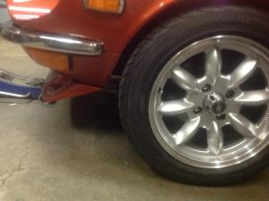
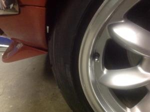
Again, I'm proof of the old saying, 'no good deed goes unpunished". I'm on a bent to improve the overall enjoyment of my Z, and a couple of days ago I decide to scrap my front adjustable control arm setup in favor of some actual suspension that knows how to soak up bumps, ie stock rubber bushings rather than bone crushing vibration passing heim joints. The installation was straight forward, stock control arms, stock T/C rods with fresh rubber bushings. Job took me till fairly late in the afternoon, and I wanted to be done in time to make it over the usual Wednesday evening show and shine at a local venue to meet up with other Z club buddies. Finished up, through on the tires, fired it up, and headed out to the show. Then the fun began. As I backed it out of the garage in to the lane, I turned the wheel and what should I hear but the lovely sound of front tire rubbing furiously on the front valance! Crap! oh well, off I go to the show. No rubbing on the way, UNTIL I get there and have to crank the wheel to get into a parking spot. Gruncccchhhh... yikes! I get out and look (finally) and sure as h-e-double l, the wheels are way forward in the wheel well. Both side nice and even, but way wrong. Great caster setting, but incompatible with my 205-50-16 tires and my stock valence. Now what the heck is going on? how can stock T/C rods cause this lovely surprise????? Pretty hard to get this wrong. Yes the control arms are on the right side (short side forward), T/C ends tightened all the way to spec. Any ideas gang? I'm going to have to go through my T/C collection and see if there is any difference in lengths, but I think they are all the same through all S30 aren't they? with one turn right, contact! Good news though, (two forward, one back remember), the ride on Calgary's rough streets is fabulous! No more bone jarring whacks. And it handles just fine
-
-
I'm about the "join the gang" here and put some rubber back in my front end. No, the Z"s front end silly! Clearly I'm getting soft in my old age and want my Z the same way. Good bye AZ Z Car adjustable control arms with your solid mounts..... Unfortunately the strut rod bushing kit AC Delco 45G25036 appears to be no longer available. Rockauto, partsgeek and others I've googled either don't have it, or it crosses to a kit that only contains the 4 rubber bushings. Moog K9215 is still out in good numbers, but also only contains the bushings, Have a look at your favorite sources and see if you can still find some. Its nice to get the new washers, central spacer tube and a new nut.
-
This is a flat plate, 4.25 wide, 3 inch long, cut to fit the lever frame. Use the picture of the plate to get the shape. A scrap of 20/18 gauge tin will be fine. 1/8 thick aluminum is too thick. 1/16 would be ok. The spacers between the level frame and this plate are 0.5 high. Use small 10-24 bolts, 1 inch long with washer to connect the plate to the lever frame especially for the left hand bolt and don't leave any extra length or it interferes with the left side of the ash tray hole. The right hand bolt can be more like a 6x1.0 metric or 1/4-20 bolt. Use bolts with thin heads or they will hit the underside of the console. I did not copy the plate in the ebay ad, I made my own and discovered the above specs and issues. Its a whole nother issue why I'm installing SU choke cables today.... I couldn't be foresaking triple carbs could I? Heavens forfend...
-
if worse comes to worst, I have a few sets of 280 tail light harnesses you can cannabilize or just use instead. Let me see a picture of the harness connector on the end that plugs into the car harness, i think there are early and late plugs.....
-
If the car was under power (foot on gas) and the car instantly died (no chugging, slowly dying over a few seconds) then its ignition cut-out. Bad Ignition unit or coil. FI cars can die quickly if the fuell pressure goes away quickly, but it's not instant. And it doesn't come back two minutes later when you re-start the car. Just probabilities here, but my guess is ignition box under the dash or the coil.
-
Holy Porsche wall Batman! Nice deek to miss him and keep racing. Also nice recovery with the yellow honda. Usual story eh? one guy screws up and many poor saps pay the price.
-
Way to go Charlie!!! From floors to doors, this cat has ya covered !!!!
-
The 72-76 wheel cylinders are just fine, other than needing to re-do the hard line since the entry point on the slave is oriented differently. Not perfect, but a very reasonable solution. Rockauto even lists the wheel cylinder kits for 72-76.
-
Granny! I have a cheap one for you. No repair. Please....
-
Time for a new strut. Way cheaper than getting it fixed. Left or right?