zKars
 Subscriber
-
Joined
-
Last visited
Everything posted by zKars
-
 The dimples are there to clear the tips of the rubber insulator mounting bolts once the x-member is in place. Put the cross member in place both ways, you'll see the difference in clearance at the tips of the bolts. Other than that, its reversable.
 -
You had a trip that went exactly as well as it should have. Congratulations, you have passed the Datsun owners test. You performed the following three official tasks to the judges satisfaction. 1. Went on a trip that was longer than you initially felt comfortable with; 2. Had problems and fixed them so as to continue safely. 3. Got home safe with a sense of intense satisfaction. Oh yes, the un-official one, "Make several un-announced live appearances for the never ending legion of Z fans. Spend time making them each feel important." RE: front wheel bearings. Just follow the FSM for wheel bearing installation. Tighten the nut to 22 ft/lbs, spin wheel both ways, loosen, re-torque, spin again, then back the nut off 60deg (1/6 turn) or a bit more until you get a line up for the cotter pin. You looseness is elsewhere. Even the splines in the steering column are often to blame for that last bit of looseness. Sorry there is no standard list of kinks. Mind you, the contents of this forum could be construed as just such a list.... No one has ever managed to fix them all and drive their Z for more than a week without another one (no matter how small) cropping up. Its as if I'm expecting another problem so you become over vigalent and every darn little squeek miss or sound you can't remember hearing before becomes the focus of the next "problem" you have to solve. Did I say "me" I meant to say "us"....
-
I hate to put a damper on the string method put forth above for toe alignments, but I think there is a critical flaw in the assumptions. To use the rear wheels as a reference, the track width of the front and rear have to be identical. And not just the official track width spec of the car, but taking into account the tires you have on the front and rear. Not all of us have the same tire and wheel size/offset on both end and there may be spacers involved as well. Never mind those of us with 3D adjustable suspension components... I'm having trouble finding a trustworthy source for the stock front rear track width on a s30 this morning (even the FSM body section isn't helping...), but I'm pretty sure the rear is narrower than the front. 1353mm F vs 1346mm R is the only one I could find with a quick google hunt. This puts your strings widening outward toward the front. Easy enough to check, just measure distance between the strings at the rear wheels and out front at the jack stands. They have to be parallel or your front toe settings will be incorrect (not as much toe in as you think). Better to put the strings on four jackstands away from the body, and get the strings parallel and wheel centers evenly spaced to the strings, THEN measure from the tire edges to the string at the front and back of the tire. DIY front end alignment- what's your method? - Brakes, Wheels, Suspension and Chassis - HybridZ And Brian/bacarl, I tried your greased vinyl tiles idea last night. Slick!!! (pun totally intended) It's a lubricating, rotating miracle! All for 4x 89 cents! It also allows the tires to settle outward as well after jacking the car up without rolling the car around. just put it down, steer right/left a few times and everything slides into perfect static position.
-
I have another idea for ya Cappy. One I tested. I have a 73 and I carry the same collapsable spare that you had in your 77 originally. Got mine from a 83 zx, doesn't matter. Since I too don't trust the "can-o-air" I simply bought a small cig lighter powered tire inflator and carry that. To make sure this was a "real" solution, I used it to inflate that collapsable spare. Worked just fine. Not all that fast, but it worked. Then I drained the pressure from the spare. It collapsed right back down to original size. Yes, they are re-usable. One more idea to get something to work. About your 14" space saver spare. Since it fits the front, but not back, you could swap tires if a rear blows out. Put front on back, then spare on front. Remember all of this is for the highly unlikely event of a flat, so a bit of time spent is worth the years of driving with sig. weight savings. I use the extra space around my collapsable spare for critical spare parts, safety gear and nice little inflator.
-
Granny, somewhere on HybridZ there are the part numbers for the Spicer Nissan trans yoke and matching diff yoke that use the 1310 U-joints that allow you to have a custom 3" steel or Auml driveshaft made that result in an unbreakable and if you should EVER need to, replacable anywhere u-joints. If you're having one made, why not? Here it is! R200 Differential to Drive Shaft Connection - Drivetrain - HybridZ Well that's close. There is another. MSA sells a 3" Alum replacement shaft as well. Probably made with the same parts
-
Ed, glad to be of service. I love a good mechanical mystery. Having a bunch of spare parts has come in very handy in many such instances. Let me know if I can be of any further assistance. The only other suggestion to make the install process easier for customers might be to clock the drive adapter differently so that it matches the stock position of the drive spindle. Plug #1 is now 60 or 70 degrees clockwise of where it sits "Stock". This forces the user to reposition plug wires which may leave some too long or too short and since the cap is so much smaller, there is less room for plug wire weaving games. I did mine like Grannyknot in post #36. You could also choose to laboriously move the drive spindle which means dropping the front sway bar also and dropping the oil pump. Messy and not for everyone. Move it one plug position CCW (looking from the top) and it would be just fine. Next batch, eh? There are also no less than at least three different distributor bases on various s30 engines, each with their own position of the hold down bolt. This in turn affects where the new clamp plate is located, which could bring up access problems to get the allan wrench on that clamp bolt. I have the zx E12-80 base on my engine, and position and access were good. Don't forget you can flip that new clamp plate over and point the bolt a different direction if you need to. Since you'd probably like to plug in the USB cable at some point to play with maps, think about where that port is located when you're done and how you'll access it. Remember too if you're driving and tuning with the cable in, there is no moisture seal around the plug. Don't tune in the rain or pack some chewing gum around the plug Hmmm, Juicy Fruit... Reading back to comment from mDec about actual verses map timing mismatch, I found that I have a near perfect match between the advance map and what my timing light shows on the damper. I did set mechanical TDC very carefully and set the little green light to "just" come on with CW torque on the rotor as suggested, during initial dizzy positioning. I suspect small errors here translate in larger problems with the real verses map.
-
Steve, with all the discussion and testing, perhaps you have forgotten the role the accel pump has in transitions? Perhaps you need to move that teensie weensie cotter pin one hole up to get some more squirt or up the size of the old pump jets? Just so's you know and as way to say thanks, all this discussion has helped me to finally go deal with my 44's little "annoyances". Seems I only had 2/6 pump jets squirting anything at all... Plugged knozzles on the jet outlets. Had to ream them out with a fine SS wire strand. While I had them out, of course there were other little lessons learned and points to mention that I'd thought I'd share. 1. I discovered that it's possible, (not that I did this, well, ok, once during troubleshooting...) to assemble the pump block with the cover that faces the carb body reversed 180, which would render its output useless. Check the gasket and body to ensure you align the outlet with the gasket and the gasket to the outlet hole in the body so the squirt has someplace to go. 2. The condition of the pilot screw taper and its seat can vary all the way across and drastically affect just how many turns is "right" for each cylinder. While I had the carbs off, I was checking the throttle blades for consistency and noticed that one side had the pilot screw tip just poking through, while the other was no where to be seen. I checked that both were the same 1.5 turns from "closed". what a difference. Who knows what the flow differences are. My 44's are oldies, they are the "Q" roadster type, and were old when I got them, so even replacing the needles might not help all that much if the seats are worn as well. How to adjust them now? At least I know the relative positions of the tips on each so I can compensate some, and the rest is by ear. What matters here is the available cross sectional area at the hole into the throat, and how much needle is filling it at just that position. 3. Everyone knows how nice and stinky these things are, fuel stink seems the norm. The bottoms of my carbs were quite fuel-ie and stained, almost to the point of being wettish. Can't imagine the stink that I will have now with 6 really strong accel pump shots every time I touch the gas pedal! I think I have a bit of a solution though to keeping gas on the inside. The base of the carbs have four locking bolts/nuts/bend-over tabs that retain the chokes and venturis. Being on the bottom, they naturally will let the inevitable puddling fuel seep out the bottom past these threads. Just a touch of thread sealant (rtv?) on the threads when you put them back in will help alot. I hope... I love the "turn off the pump exactly one fuel bowl's worth from home" approach. Nice. 4. Transition holes and their location and idle settings. One thing that is not clearly covered in the Mikuni manual deals with mechanical idle settings. Webers have this issue too. It's mentioned briefly above. There is a terribly fine line between throttle blades closed (no idle possible), throttle blades open just enough to get some kind of low idle speed, and too much throttle blade open that exposes the first (or second!) transition holes. To get idle mix right with JUST the pilot screws you need to have enough idle to keep the car running, but NOT have the blades open enough to expose that first transition hole in the roof. With the carb in my hand, from closed blade to first trans hole 'just' peeking open is BARELY one full mechanical idle speed screw rotation. If you have a lumpy cam, or things aren't tuned close to right yet, you get VERY tempted to turn that idle screw up some more to get the dang thing to run while you twiddle, but DON'T DO IT! Exposing the transition holes while tuning idle will likely give you that flat spot in transition off idle, which will make you increase you pump shot or pilot screws turns out, but you're chasing your tail at this point. Take one carb off and determine how many turns you have until that first trans hole pokes out on the manifold side. It also shows you exactly where the mech idle screw starts to move the throttle blade. If you have to have a higher idle, I'd be plugging that first trans hole. 5. If the carbs aren't new, or you didn't get your jets from a known and reliable source, don't trust they are all the same size! Well mine were, but the mains were half 150's and half 80's! yup, 80's, at least that's what they said on them. But the 80's had been drilled to 150's.... Thanks to Todd for pointing out that possibility. Also later discovered my pilots were half 60 and half 65's, again, 60's were drilled to 65's. Drilled jets don't perform as consistently as factory jets. This thread pretty clearly indicates how small changes make big differences in performance. Don't need to have inconsistent jets too. 6. The short 5mm screws that hold the stock Mikuni linkage to the body. I discovered one I had substituted was just a hair too long. The choke in that one barrel now has a very slight extra 'wave' in it. Let's just call that a "venturi laminar flow disturbance" experiment.... Also the same holes exist on the other side of the body, and one at least empties right into the barrel behind the choke on that side. Does this cause a slight leak around the choke from the outside? Maybe, plug them (with SHORT 5mm bolts!) 7. Jetting for different displacements. It seems the "right" jetting for 2.4 and 2.8L engines discussed here are pretty much the same really. If I had to average what I've read above, would it be 190-200 air, 150 mains, 60-65 pilots?. I have a 3.1 stroker, but I'm using the jets as the rest of you. I have 34mm chokes. No, bigger engines do not simply need bigger jets or bigger chokes. Its about being able to supply enough fuel to supply the air flowing through to keep the APR's where you want them. 8. Get your timing, idle vacuum, engine temp in spec and carb/mani and mani/head gaskets sealed before proceeding with any carb tuning. Can't imagine how I tuned these things before without a wideband and vacuum gauge to refer to. What does vacuum on one runner of six mean anyway? What if you have a lumpy cam? Retarded cam timing? A subject for another post. And Mitchell, that plug reading chart is something we should ALL commit to knowing by heart. Thanks for posting it, as well as the other references. Great stuff.
-
The spring under the head is supposed to keep the tension. Its worn out or broken. Replace the spring, or add a washer to increase the pre-load.
-
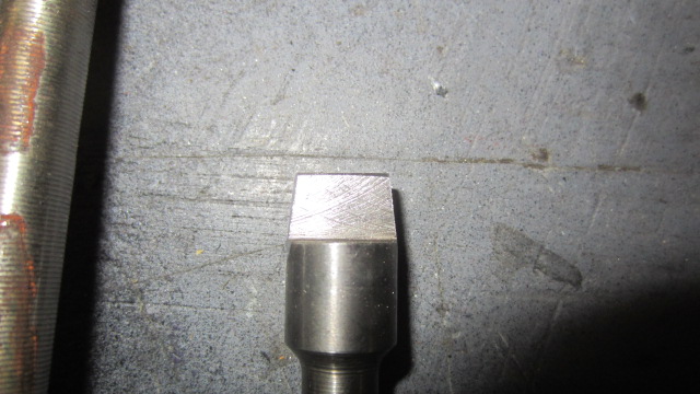
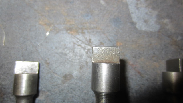
Ed and everyone.I just got in from the shop. I know what the problem is, and its NOT too small an ID!!! The rectangular slot in center is TAPERED narrower as it goes deeper in the body of the dizzy. The tang on the spindle that engages it is NOT tapered, so depending on how much your particular tang is tapered from wear, it may or may not fit in. I have 7 spindles here and NONE expect one fit. I measured and measured sizes and all were identical. But two of them fit better than the rest. Once I saw what the difference was, ie one had a very worn (and hence tapered) tang, the pieces fell into place. I ground one tang down to taper it toward the tip on both edges and it slipped right in to complete engagement depth. Ed you have to re-machine that tang slot so it stays at the same width the whole way down. Those of us with dizzies have to pull the drive spindle and taper the tang. Reducing the width by .05 at the end compared to where it end being cylindrical is all it will take. BTW every one of the 7 spindles had an identical .4885 OD to the cylindrical section. The dizzy was already .4950 or better ID, so it was never the problem. Here is the picture of what I had to do the tang. I'm pretty sure t'is more of a taper than I needed to create. This is the best spindle I have for comparison (center). Note how straight the sides are. The one on the left has a badly worn left side taper. I just about went all the way in with no pressure. The straight sided one would not engage the slot AT ALL.

-
Nothing better than knowing you're not alone! Thanks for the quick response, Mike. I'll let Ed know directly so he keeps on top of the problem. I'm sure he'd like to know why the drive end is all ground up if I ever return it for waranty work! Mine was purchased in the last 3-4 weeks.
-
Carefully consider your reasons for wanting rear disks. If you're keeping your stock wheels and hub caps, it can't be for appearance reasons. Properly set up rear drums with modern friction materials are all you need for street driven Z. Concentrate on upgrading the front brakes first, but again, like-new condition fronts with great pads are ALL you need for the street. Yes, really. Make sure your master is up to snuff, fresh fluid, and a proper bleed. Make darn sure you keep the front / rear relationship safe. Last thing you want is more rear than front. Do some more research and be honest with yourself about why you want disks in the rear.
-
Hey gang, this weekend it was my turn to put in my fresh and purdy 123 Ignition dizzy. Few details to share. Generally the install went as described above. Schlik. Love having only a few degrees advance for starting, and full MAP compensated control. But there was one gotcha. Read on. My issue is with the fit between the end of the drive spindle in the front cover and the base of the new dizzy. Its WAY too tight. When I first put the thing in, I had trouble getting the rotor to lock into the drive spindle. I really had to reef downwards while twisting the rotor to get it lock into the slot. Even then when it finally did catch, it felt like it just barely engaged. I went around to the passenger side and looked to see if the dizzy was all the way down. Nope. Its up about 1 to 1.5 thicknesses of their nifty little lock plate too high. Sorry no pics but its clearly not even close to all the way down. I removed it and grabbed a spare spindle I have laying around and sure enough, I could only get the thing all the way engaged by tapping it in with a hammer, (which I only did about 0.05) as I would likely not have been able to remove it with more force than I wanted to use. I measured the end tang, and its mating slot in the dizzy, they can fit okay, but the outer diameter of the shaft and ID of the dizzy are very tight tight interface fit. Now I appreciate a tight joint for this application, but I can't seat the dizzy without rubber hammering the body down (didn't do that, but would have to), and then I am sure it would be a royal bi$!)h to remove it. At the moment, I have not resolved this, but it seems like a little reaming/Dremel drum sanding of the ID of the dizzy to make more room for the shaft is the easist solution. I'd rather not remove the spindle and reduce its OD. It also possible that the location of the slot in the end of the dizzy is slightly "off-center" (I know its not in the center) so that as the tang begins to engage, it is pulled sideways and locks the OD against the side. Doesn't feel like this is the case when I play with the spare shaft on the bench, its just crazy tight going in. So what say you other users? I want to hear from Mike W, Granny and mDec and tell me your situation. Did you have similar problems, or did yours schlip right in like nothing? Maybe you should go out and check if yours are really seated ALL the way down! The base of the dizzy plate and their new lock plate below that, should be totally flat to the front cover mounting surface. No gaps allowed. If your dizzy body is slightly wobbly when you push it side to side, then its not all the way down. Since Mr. 123IgnUSA is watching/listening to this thread, any similar reports from other users? Jim
-
You could take a freshly sand blasted datsun fender and put in the full sun in the Mohave desert in August, and it would be rusty in 72 hours.... If you want to get all scientific about it, Air + the earth and its oceans => wind => clouds => humidity => rust. Fast or slow, its gonna getcha!
-
We are going to need a picture of these wheels. The only Nissan alloy wheel that came on North American 78 280's is not a "turbine" style wheel. http://www.classiczcars.com/forums/body-paint-s30/21653-newly-painted-280z.html post #13 shows the wheels and hub caps there were the only factory options in 78. Someone else was asking about center caps a couple of days ago. There were several suppliers mentioned.
-
There is your problem right there. 4.5 turns is a million too many. Rich rich rich. Your plugs are loading up and this is causing your poor performance during actual use. Please, just humour us, put them at 2.5 and spend a day with it. I will gladly be wrong if this is the not the issue. From there, please get access to a wide band O2 and a vacuum gauge, and stop guessing about what the problem is.
-
Check for vacuum leaks as well. Tighten the carbs down, check the manifold bolts too. Are both enrichment knobs turned out the same, and approx 2 1/2 turns? Don't blame the carbs until all other aspects of the tune are corrected first. Timing, valve lash, vacuum leaks, bad plugs, low compression, bad wires, cap etc are all out of ztherapy's control.
-
How about this? Replace the stock nub washers (they are called 'Stoppers' in the fiche) with thick all-rubber washers. This replaces the stock nub washers compliance with more rubber, thicker than the nub washers so they compress when tighted down, and you have a chance of using different durometers of these washers in a effort to both increase stiffness and maybe affect sound transmission. No danger of metal washers coming in contact with the center sleeve. Hey, get real fancy and make multi-layer washers with different density layers to reduce sound transmission (each density change creates another reflection interface). You knew we'd have to start re-engineering this and start using 2$ words, didn't you? One source of really tough rubber washers of the right diameter and thickness might be the muffin tops (sliced off) of a set of poly replacement MBar bushings...
-
I'm assuming you're thinking of putting your spacer/preload washers between the MBar and the two stock nub washers to get the nubs to touch/compress against the MBar eye. You must be sure the ID of those new washers is LARGER than the OD of the central sleeve in the MBAR bushing, ie does not touch it, or you will create a metal to metal sound pathway between the outer Mbar eye that the new washer now rests on, and the central sleeve, which is in tight contact with the frame above. However there is nothing to keep this washer from migrating off of center eventually, and coming in contact with the central sleeve again. Think carefully what tightens against what and how rubber isolation is kept when this is all assembled or it may result in things getting worse, not better, or changing over time, confusing this more. You really need nub washers with bigger tougher nubs to increase preload. The stock rubber bushing system was designed to contrain a stock torque level drive line with a non-LSD diffs etc. I'm not sure you/us/we can get the balance of stiffness and sound isolation we crave with our "improvements". I hope I'm wrong...
-
The moustache bar bushing rubber is likely old and soft or beginning to break down. Tightening down the nut just locks the bushing's center steel tube and the steel face of the washers to the frame, you rely on the hardness of the "eye" bushing rubber and the hardness of those "nubs" on the upper and lower washer to prevent the rotation/twisting of the M-bar that might allow it to touch those up-rights or anything else. Squishy bushings will let it twist all over the place. I'd love to have a go-pro and a light back there and take your car for a good spirited drive to see just how much that m-bar twists around. I am also facinated by your earlier comment about diff whine increasing when you put the front diff mount back on. I think you've just increased and/or created a better/new vibration path from the diff to the body rather than a change in driveshaft angle being the source of the increased noise. I just experienced something similar. I installed a new transmission insulator/mount and put poly bushings on the trans mount cross member ends. I did this to see if it would raise the trans tail to correct the driveshaft angularity, thus eliminating some driveline vibration I have. Well the end result was both good and bad. My driveline vibration is drastically improved (new trans mount insulator was a good 3/4" taller/thicker than the squished worn old original mount), BUT I now have much louder diff whine AND transmission noise! Did the drive shaft angle change this or is it the new poly bushings in the cross member that transmit more noise to the body? BTW, to stay on topic a bit more, I also have a few clunks in the rear, and have very close M-bar/upright clearance with R200/Z31CLSD finned cover/brace etc, and when I put a pry bar between body and M-bar near the ends, I can move/twist the bar pretty darn easy. My M-bar bushings are really soft and the nubs on the washers are half worn out and soft too. New ones are on order. Had to come from Japan, all out of stock in Canada. Used to have the poly bushings, but then again, the diff whine transmitted was un-bearable. I'll have to experiment with some thin materials at the Diff/Mbar contact and Mbar/body mount points to see if we can't reduce this transmission.
-
Plug them. Connecting them short circuits the head cooling system. This has been discussed at length here and on hybridz. This didn't make perfect sense to me initially, since doesn't having the heater on produce the same short circuit? Well yes and no! The heater valve and the heater core are a significant restriction compared to a wide open 5/8 heater hose, AND more importantly when the heater core is loosing heat it is helping the overall cooling process. Its just so dang tempting to just put a single hose with two clamps between those two nipples.... No need to find two big fat bolts or plugs of some kind and "4" hose clamps... Fine in an emergency road repair short term, but don't be lazy!
-
Lots of curiosity today it seems. Can you give us more details about the engine build? What was done to get 3.1 litres? Are the Mikuni's 40's or 44's?
-
I may have discovered your initial "Rear too low, front too high" problem after the initial Eibach install. The 6203-001 springs are the fronts, the -002's are the rear... The picture you show in post #1 where the 6303-001 part number is visible on the very very short spring next to the stock rears was the clue. Many many of us have been caught by that little detail in the past. You likely accomplished much the same spring rate by using a shortened rear spring anyway. Someday when you're bored you can switch the Eibachs around and see if you prefer the ride and likely somewhat lower ride height any better. It looks just fine the way it is.
-
Sorry for the delay there. The ebay fittings you link to are close but not correct. Those have parallel threads (straight) not tapered. you need BSPT not BSPP. Regarding the other question, only the pipe/sensor fittings are BSPT. I'm assuming you don't mean the various bolts that hold things together. THey are standard metric stuff, 6x1, 8x1.25, 10x1.5. This one looks more right. BSPT Male to NPT female. http://www.ebay.com/itm/Auto-Meter-2269-1-8-NPT-to-1-8-BSPT-Oil-Pressure-Metric-Adapter-/201055603779?pt=Race_Car_Parts&hash=item2ecfd90c43&vxp=mtr I just searched 1/8 BSPT adaptor, got lots of hits. Autometer makes one. http://www.autometer.com/cat_accessorieslist.aspx?pid=11 Try your local speed shop.
-
Kacrow76, I believe C.O. and Wade will thank you for this post as it justifies all the effort and thought that went into this excellent discussion. The answers to your questions are, in fact, all explained in the text above. I suggest you re-read and see if additional insight can be gained. You are indeed missing something. One clue; Beauty is in the eye of the beholder....
-
I've had no luck finding then either. MSA has a Polyurethane "equivalent" that is designed with integral camber ajustment (anybody ever try these?), check these out. Motorsport! Street Camber Kit, Front, 70-78 240Z-260Z-280Z - The Z Store! Nissan-Datsun 240Z-260Z-280Z-280ZX-300ZX(Z31/Z32)-350Z-370Z Parts @ $130. Not bad. As for affordable OEM parts availability, search for 54320-E4100 on ebay, there are a few OEM parts from a three supplies with these in stock for ~$55 a piece. Does your 260 have rear insulators the same short height as the fronts or same taller ones (54320-N3701) as 280's? The fiche seems to indicate 9/74 and later needs the taller ones but check before ordering. Only one ebay seller for the tall ones, at $162CDN.... MSA lists them too, @ $214.95