Jeff G 78
Free Member
-
Joined
-
Last visited
Everything posted by Jeff G 78
-
 Yeah, I will call them tomorrow. I just spent an hour chatting with Tony D and he couldn't come up with any good explanation. Hopefully Steve at ZT can offer some advice. I have a set of rebuilt SU's being Fed-Ex'd to me tomorrow to borrow for the race, so if ZT can't help, I'll do a swap on Thursday before I leave town.
 -
Checking with engine off and electric fuel pump. I can check them in the bowls or in a plastic test bowl with the same result. Both carbs do the same thing. I can watch the float rise and when it stops, the float to lid is way closer than the spec - yet it's still low.
-
I am at my wit's end on my racecar. I cannot get my SU fluel levels to set right. Both bowls are 5mm low no matter what I do to the floats, valves, or pressure. I've tried everything I can think of, but I am now out of time. I leave for a race on Thursday afternoon and I have no confidence that I will get it to run right. I'm looking to borrow a set of known good SU carbs that I can have overnighted to me right away. I'd have them for about 1 week. After my race, I plan to send mine to ZT if I can't solve the problem, but for now, I need something that works. I just built a 2.8" 9.5:1 motor with a mild cam that should make about 175 RWHP, but it won't do me any good if I can't get the carbs to work right. The first time I will know for sure is on the track as the car is not street legal, so all I can do is tune mine in my driveway and try to compensate for the low fuel levels. I know it's a lot to ask, but I'm out of spit.
-
Check your head for warpage. If the head was warped an a machine shop milled it flat, the TOP of the head will still be warped. A warped top will force the cam to bind and break. Run a straight edge along the valve cover mating surface and check all along between the straight edge and head with your thinnest feeler gauge. There should be zero gap anywhere front to back. If you don't have feeler gauges, shine a flashlight at the joint and see if light bleeds though anywhere. I would not swap the towers. I leave them alone and just keep the cam, rockers, and lash pads together.
-
-
Here is what I did. Keep in mind that I am thrashing to finish my race car, so I didn't take the time to perfect the plastic bowl, but it does work. I like Blue's idea of doing the bowl work first using water. I wasted WAY too much time this weekend trying to get my float heights set. I'm not sure I ever did get then right. I have to get to bed, but I'll explain more later.
-
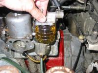
OK, today/tonight was a really rough experience, but I might have found an easier method of setting float heights. I was using the sight glass method today for the first time on my new engine to set the floats. The front carb went OK, but the rear carb was giving me fits. I decided to take a different approach and I cut a plastic water bottle in half so that the bottom of the bottle was roughly the same height as the carb bowl. I set the lid on the open container with the float hanging inside and measured down 20mm from the bottom of the gasket (3mm from bottom of gasket to inside of lid) and I put a sharpie mark on the plastic container. I then turned on the pump. With the container setting on top of the SU bowl to get the correct angle, I could now watch the fuel fill the "bowl" and watch the float itself. This is by far easier than messing with the real bowls each time. Within seconds, I could tell what the height was without the need for a sight hose or the hassle of wiggling the lid into place and risking gasket damage. I could make changes to the float in 1/4 the time it took me to put the lid on the carb bowls and it was super easy to see the fuel height directly rather than indirectly through a sight glass. In the end, I decided that I need new float valves ASAP. I have emails out to all Z owners near me. I have to get it ready for a race next weekend. Hopefully I'll have the parts I need tomorrow. If not, I'll be making an emergency plea for help. I'll take pics of the setup tomorrow if I have time.
-
Wow, thanks guys. I never realized that I needed that much initial with the cam.
-
Steve, I thought exactly the same thing about pulling the vacuum hose, but the FSM never mentioned it. I reread the instructions several times and it wasn't to be found. It makes me feel better that 17° initial is normal. I can probably get it to run there. The chart shows 8° static, 17° mechanical and 30° vacuum for my '82 distributor. So, I should run the 17° initial, and plug the vacuum advance? I have never studied timing, so I'm at a bit of a loss as to what the vacuum does. I understand the mechanical better, but not the vacuum part of it.
-
I have a design worked out, but I have been spending every waking minute prepping my 260 for a race next weekend, so I never got around to making them. After the race, I could probably knock a few out. My plan is to use 1" acme thread rod to get maximum wear and pulling power.
-
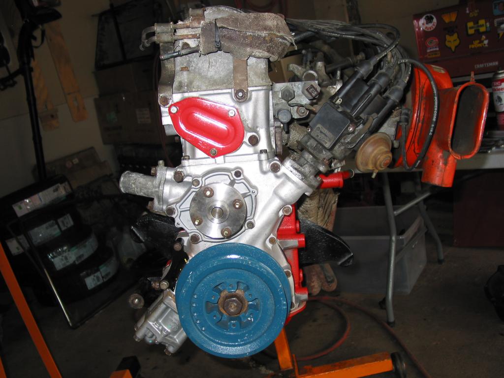
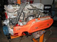
Sure is purdy Guy! I fired mine up today. After many stupid problems that appeared out of the blue, it fired up within about 2 seconds and purred immediately. So far, the new MSA exhaust sounds great. I went with four hangers and it really helped the alignment. Other than the muffler hanging lower than I'd like, the rest fits really well. I have an ignition timing question. I *thought* I remembered checking the idle timing with the vacuum hose removed, but the '78 FSM didn't say anything about the vacuum advance when setting timing. When the distributor is at mid-slot, it idled at about 1300 RPM (pulled the carbs from my race L26 and didn't touch them) sounds great, but the timing light shows a ton of advance. It was something like 20° or more. I adjusted the idle screws to get the idle down to ~800 and then turned the distributor and got the initial timing down to about 14°, but it started running rougher and had a delay in throttle response. When I clamped the vac hose, it wanted to stall. With the vacuum advance in place, I checked the total advance at 2800 RPM and it was 46°. I am running the stock '82 NA distributor which, according to the distributor advance curve excel file, that dizzy should be at around 55° total advance. I'm really shooting for a lower number like high 30's with the higher compression. So, my question is, how do I set the initial timing with that distributor? What am I doing wrong?
-
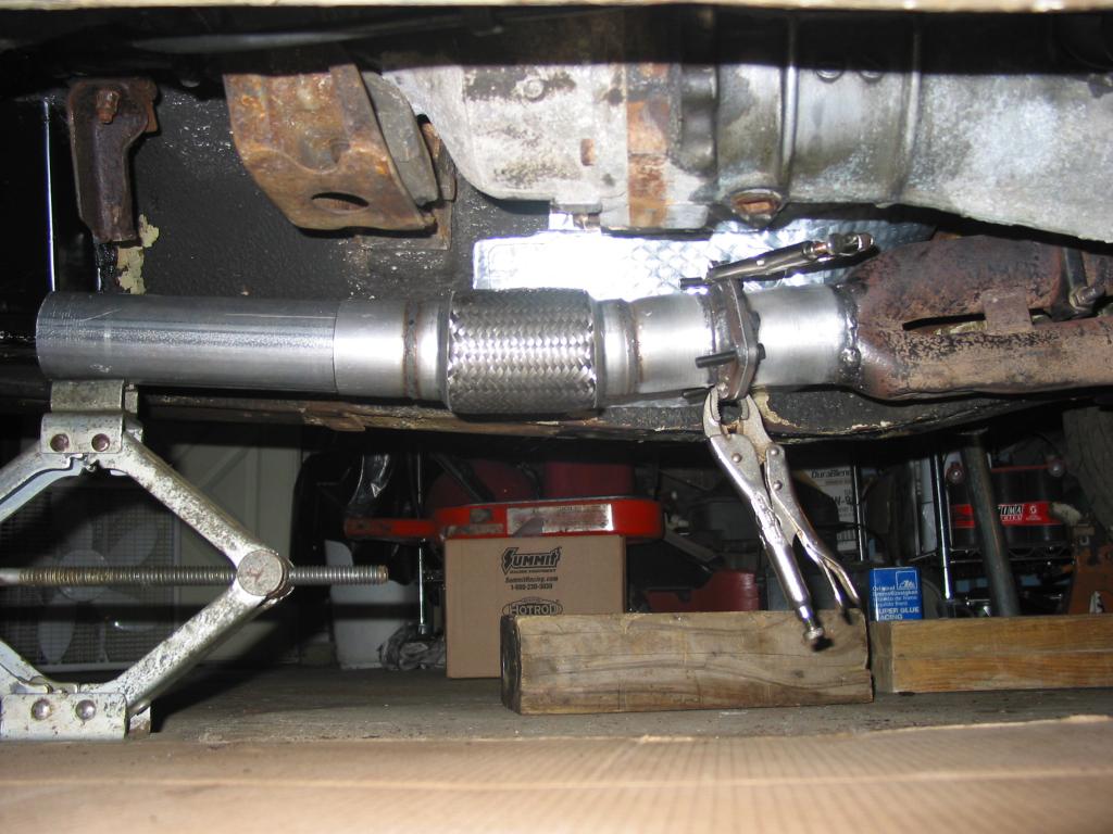
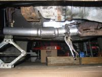
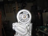
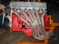
Here's what I did last night. This was my first solo engine install. I've always at least had a spotter to watch the other side and help guide the engine into position. Here's the flex pipe on the end of the collector. You can see how it helps the alignment between the header and the exhaust pipe. I also added heat shielding to the tunnel to help keep my feet cool. I should have it running later today.


-
Guy, the indicator goes on the valve spring cap and you need to go through the full lift, so .5" range is just barely enough, but I find myself moving it at least 4 or 5 times until it doesn't over travel at one end or the other. You need a bit of extra travel at both the top and bottom of the stroke, so 0.5" range minus cam lift at zero lash (0.460" in my case) is only 0.04" and then divide that by 2 and you end up with only 0.02" to work with at each end of the indicator stroke. Does that make sense? To find TDC with the head off would be simple with a dial indicator. When it comes time, I'll walk you through it rather than go into the details now. Make sure you take lots of pics and keep us posted on the engine build.
-
Guy, you can get everything at Grainger or on Amazon (what CAN'T you get on Amazon???). I got my Mitutoyo about 25 years ago. The only regret is that almost all of them read 0 - .5" and the cams have roughly a 0.450" lift, so it takes a lot of fiddling to get both the zero and max lift within the range of the indicator. They sell 0 - 1" range, but the price goes way up. Expect to pay over $200 for a 0 - .5" and quite a bit more for a 0 - 1". Go with 0.0005" resolution. Of course, you can find something WAY cheaper if you don't go with Mitutoyo. I'm sure Harbor Freight has them for $10 I think this is the modern equivalent to mine at Grainger for $226.50. MITUTOYO Digimatic Indicator, Battery - Electronic Digital Indicators - 5C711|543-783B - Grainger Industrial Supply The 0 - 1" jumps to $485.25. MITUTOYO Electronic Indicator, 0-1 In, Flat Back - Electronic Digital Indicators - 4GPY4|543-476B - Grainger Industrial Supply Here is a magnetic base by Mitutoyo for $201.50. MITUTOYO Magnetic Base - Indicator Holders, Bases, and Stands - 22N461|7033B - Grainger Industrial Supply The degree wheels can be found anywhere, but get a large one. The one I made is 16" diameter and it isn't too big. Summit Racing sells every size and brand.
-
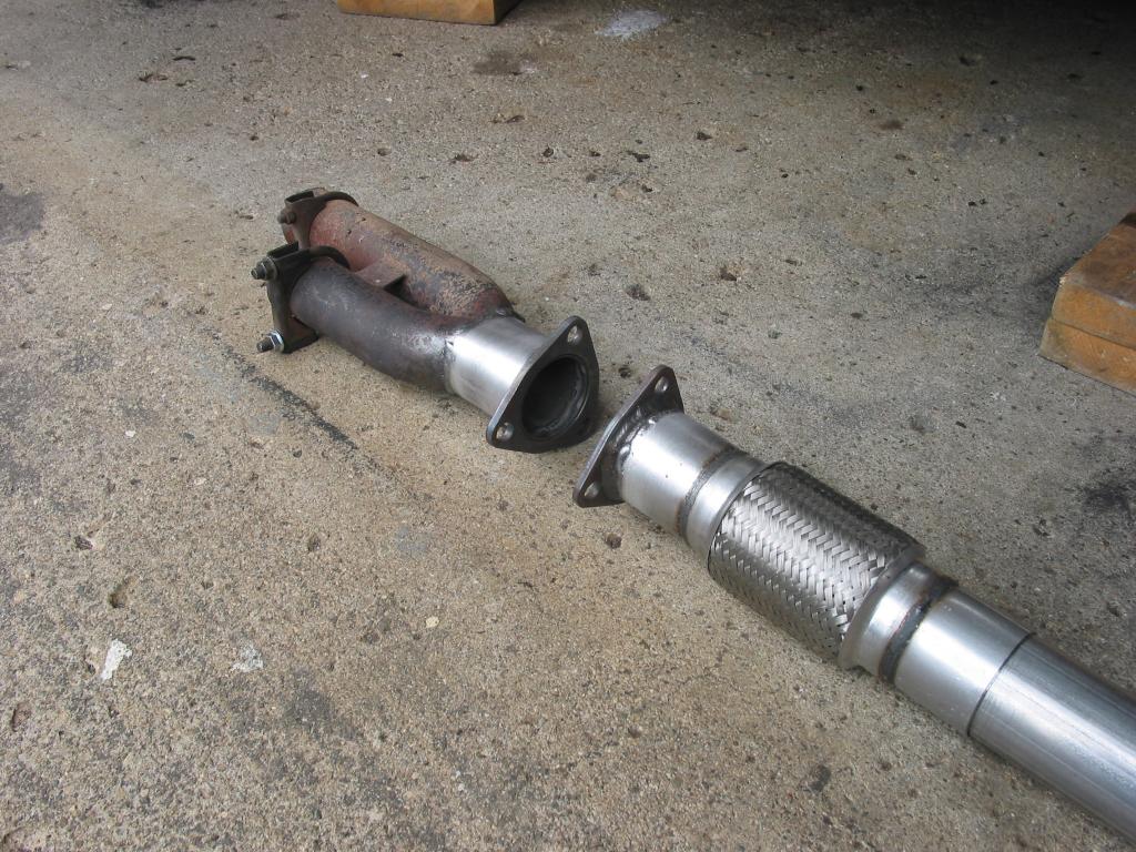
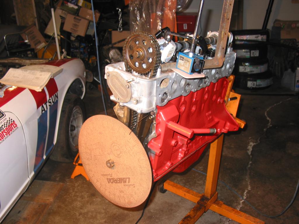
I really like my Mitutoyo digital dial indicator, but it wasn't cheap. Spend the money to get a good magnetic holder as well. My Craftsman one is serviceable, but I wish I would have bought a better one. You will also need to make a piston stop. The easiest way is to break the ceramic out of a spark plug and insert a long bolt with the end rounded. Mine was made about 20 years ago in 15 minutes, so it's really crappy, but it does work fine. Someday, I will redo it by welding the bolt to the spark plug rather than rely on all of the washers and the nut. The degree wheel is actually made of wood by downloading a jpg of a degree wheel and cutting/etching it on a CNC laser. My racing teammate made it at the Tech Shop which is a local shop that is run like a health club with monthly membership dues. Do an internet search on how to use a degree wheel to get the full instructions. I will give a complete review after my race on the 13th. I am also adding a flex pipe to the exhaust right behind the header collector to take the strain off the manifold studs. Once the engine and exhaust are installed, I'll take more pics. I'm using the slip together MSA 2-1/2" exhaust system.


-
I used a degree wheel and the cam card. It's a fairly slow process, but it gets it exactly right. Find #1 TDC and set degree wheel to TDC using a piston stop. Measure 0.050" #1 exhaust valve open and compare to cam card Measure 0.050" #1 exhaust valve close and compare to cam card Install offset bushing that moves cam the right direction to match cam card Repeat until valve timing matches cam card
-
I thought you'd like that Guy! I have your other one on my L26 race engine. Thanks again for them!
-
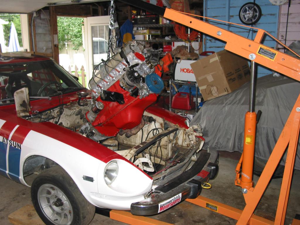
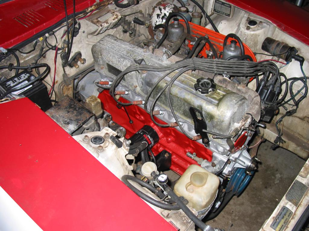
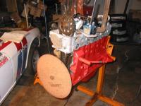
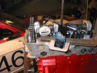
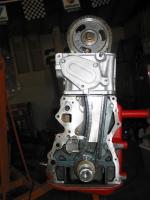
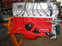
I've been busy building my engine. The race is in a little over a week. Here are a few pics of the timing with the decked head and no tower shims. It's a little too pretty for a ChumpCar engine, but it should run pretty well.

-
Nope, it's a CWC blank with a stock base circle.
-
Will do cliff. I should be able to report back in about 3 weeks how it performs on the track. When I had the cam in my L26, it really woke up the engine. I don't think it lost much on the bottom and it pulled to well over 6500 RPM. The engine was old and tired though, so the overall power output was still low. With my new F54/shaved P79 motor and the addition of a header and 2.5" MSA exhaust, I should be making around 175 RWHP.
-
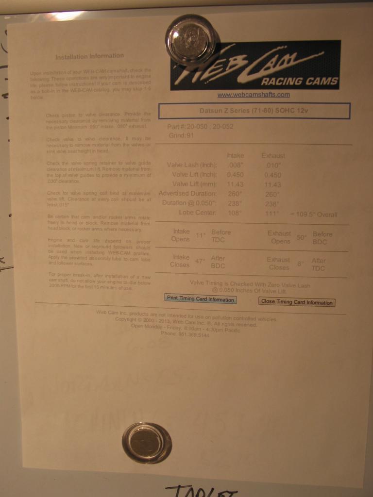
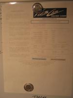
Leon, I run a Web Racing camshaft. Here's a quote from Bryan Little's website: "Webcamshafts of Riverside, California is worth checking out. They have 50 years experience with creating custom and antique engine grinds as well as a couple of decades of producing Zcar cams. And after talking to them on phone they appear to really know their stuff. It turns out they use CWC billets for their new Z cams and also create reginds (your choice), but they "Nitride" them which involves heating them to 900 degrees and in an ammonia gas chamber. Nitriding creates a super hard lobe surface and is considered to increase the life of a cam 10-fold." I also use only VR-1 oil which might help and I run a turbo oil pump which might have increased the flow enough to provide some oiling. All I know is that I got lucky.
-
Leon, the rockers and cam lobes look perfect. There are no signs of any starvation.
-
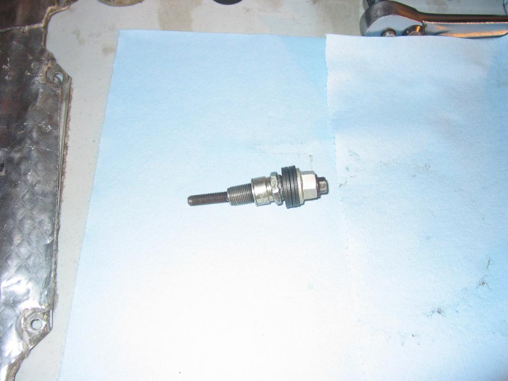
Thanks everybody. Steve had it right with 1/4" NPT. I found a plug at Napa and installed it with red Loctite. After looking at the plug, it must have never been there. There is no way it could have come out and not been stopped by the cam cover.
-
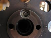
Pete, I did not clean it before taking thee pic and I can't tell what the thread is since they start about .3" deep in the hole. When I insert my thread pitch gauge, it is too hard to see the results due to the depth of the hole. I tried my tap and die set and none fit, but it was somewhere around 1/2". The minor diameter measured about .4" with my calipers. I will try a 1/4" NPT plug today after a hardware store run. I only have 3/8" NPT and larger plugs at home and all were too big.
-
Nope, no spray bar Steve. When I installed the Web cam into my L26 in 2011, I removed the spray bar and added the spray bar block off plates to the towers. Even if I was using the spray bar, the problem would be the same. No pressure would ever build in the drilled cam with the plug missing. I have spent hours tonight trying to come up with a logical solution and I'm drawing a complete blank. There is no way the plug could have come out while the cam was running in the car because there simply isn't space between the end of the cam and the cam cover for it to back out all the way. I measured the cam to cover distance at around 1/4" and the plug would have to be deeper than that. Had it backed out far enough to be loose, it would have rubbed on the cover and there are no witness marks on the cam cover. As for me losing the plug, I can't come up with any way that happened either. I pulled the cam out of the L26 which was out of the car and sitting on the garage floor and I carried it 5 feet to the workbench where I later noticed the missing plug. There is virtually no way for it to fall out in that time frame and I would have heard it hit an found it on the garage floor if it had. As for the plug, I'm not sure the CMC billet Web camshaft uses a pipe thread. It is threaded in close to 1.5" and it does not appear to be a tapered thread. If it is, that will make life easy, but it sure doesn't look like a pipe thread to me. I'm stumped... I agree that it should have chewed itself to pieces running without the plug and yet everything looks perfect. Maybe VR-1 oil is just that good?