240260280z
Free Member
-
Joined
-
Last visited
Everything posted by 240260280z
-
 Hi, The 4 bolts that hold the two differential rear hangers to the box frame cross beam broke when turning out. I tried PB blaster and heating the remaining studs with a MAP torch, quenching and turning out with an extractor but no luck. Today I had a welder with a 120V flux wire mig have a go but the welds would not take to the studs. They broke when turning. He also had problems welding the nuts to the studs... the washer seemed to weld ok. It seemed like the nuts may have been a poor quality steel... not sure? Any tips on how to do this job? Does it need more heat with a 220V higher current welder? Thanks
 -
Hmmm the only z link to whales I have read is here: http://www.atlanticz.ca/zclub/zinfo/zfun/carofthemonth/carofthemonth.htm
-
Awe come on, that was my teddy bear look... I did a study of a self portrait... here are the ones to date. More to come


-
Current is charge flow per unit of time. DC or AC car or household does not matter. ... talk to Mr. Coulomb. The biggest factors affecting flow in wire are: 1. Material of conductor and purity (affects unit length resistance) 2. Effective cross sectional diameter of conductor I work with undersea submarine cables whose electrical loss is 0.7 ohms per kilometer.
-
Thanks! That actually helped a lot! I have 3 transmissions and I got the 71 4speed (monkey box) mixed up with that one.
-
Will do. Thanks again!
-
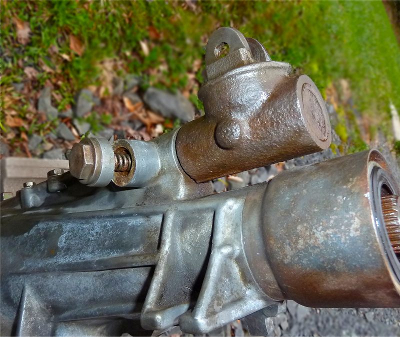
Just cleaned up a 4speed z transmission and noticed a crack in the casing (see attachment). I tried to turn the bolt to inspect further and it let go. Is this a common failure point?

-
Thanks guys. The drive shaft is done. I'll bring the 1/2-shaft parts to my home where my big @$$ vise is and try that method. For reference here is a hammer technique: http://www.mustangandfords.com/howto/5208_universal_joints_replacement/photo_11.html The anti-seize in the machined holes sure helps the cups seat effortlessly.
-
Is it OK to tap new U-joints together with a hammer rather than a vice? I also used antiseize, block of wood as shock absorbing base and a socket for distributing the hammers tapping to the outside of the u-joint cap. It seemed to work like a charm but most instructions I see use a vice.
-
Stroker with ITB and megasquirt would be a fun project.
-
I tuned a few Z's with O2 sensor and ~ 14.7 at idle worked nicely. For balancing you can do Norm's test and lift one carb piston at a time to completely to disable it and compare O2 between each non-lifted carb+ all that extra air from the hole you make. A/F goes to 27 or something crazy lean but the readings should be same for each carb when balanced. You can do this at idle and at 3000 rpm for completeness.
-
Pour in a small amount of oil (or grease/anti-seize the bottom of the strut) before inserting the shock prevent it corroding to the strut well's bottom. Once the shock is inserted, fill the strut cavity with oil then grease the top cap and secure. The oil transfers heat from the shock to the outer strut wall. It does not matter what oil you use. 10W30 motor oil seems be easiest to grab in most garages that I have done shocks for friends.
-
Heating is due to current and resistance. The resistance of a fusible link and connections should be ~0 ohms therefore the heating should be ~ 0 Watts however if the connections to the fusible link are loose and/or corroded.... or the wiring to the bottom of the fusible link holder is corroded then this adds resistance and, in turn, heating. Heating is proportional to I²R where I is current and R is resistance. As mentioned your lights draw ~ 11 amps however the resistance of the link should be ~ 0.01 ohms so the radiated power should be ~1.2 W If the resistance of the fusible link was increased to just 1 ohm due to corrosion then the heat would be ~ 120Watts... try holding your finger on a 100W light bulb to get an idea of that much energy.
-
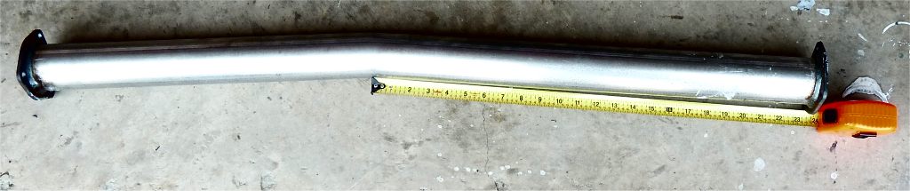
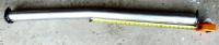
I look forward to your experiment's findings! FYI: Here ia a hack job of an 18" X 2.5" ID on my 280z:
-
See Attachment:
-
To0k this photo yesterday but only got it on my computer today.
-
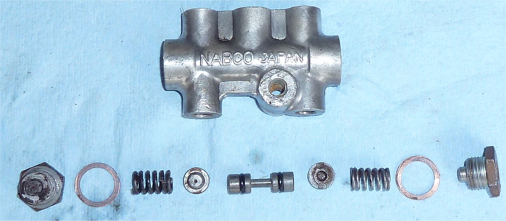
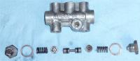
Had one with bad threads. Needed the switch contact. Took it apart for your viewing pleasure:
-
Sometimes bad points causes high rpm bog that seems like fuel delivery problem.
-
Thanks! I should be able to get locally now that it seems to be a current part number You are kind!
-
just searched the part number and got this Looks like a new bag and new part number Dang Hybrid Z doesn't allow external links to photos... great Z community spirit.... NOT
-
Thanks, I got Differential to 1/2 shaft part (34) bolt 38228-21000 here: http://carfiche.com/fiche009/s30/5/g15.gif Differential to drive shaft part (2) bolt 01111-00051 here: http://carfiche.com/fiche009/s30/5/g06.gif part (3) nut 01223-00041 Drive shaft to hub part (19) bolt 39628-E4100 here: http://carfiche.com/fiche009/s30/5/i16.gif however my local dealer typically can not use these numbers. Is there an on-line cross reference anywhere? I bought a Nissan parts tool CD but it only went back to '83.
-
Hi, My local Nissan dealer can only order newer part numbers. I need the 4 flange bolts and nuts on each side of an early R180 differential from a Jan 71 240z. The bolts are somewhat unique and have a quadrant shaved off for clearing the round plate that protects the seal. Would anyone happen to have a part number? Thanks!
-
I am installing exactly the same on a resto. For sound insulation I will use either peel and seal (Home Depot roofing section) and/or foil backed bubble wrap (Duct Insulation Wrap). Here is a sample of peel and seal: Here is what the duct insulation bubble foil looks like:
-
I just edited wiring diagram to make it easier to follow. See attachment.
-
I think there is a bad wire or connection in your circuit that is preventing the alternator from knowing what the battery is doing.... the alternator is supposed to work with the battery as a team and the yellow sense wire is how the alternator knows what the battery is doing. It is also possible that the fusible link is current limiting the output of the alternator. It could be corroded. Two 70watt headlight bulbs will only draw ~11 amps so the alternator should be able to handle that no problem. Try this: 1. Connect a new wire to the "S" connection on the alternator and connect the other end to the +pos post on the battery. If this works then your sense wire in the harness and its connections need to be refreshed. 2. Clean all +12V cable connections between battery and alternator. The path is: - Battery to starter - Starter to fusible link - black fusible link - fusible link to alternator You can check the wiring path interconnections on this drawing: http://www.atlanticz.ca/zclub/techtips/wiringdiagrams/F77ZCAR-WIRING1.pdf