zclocks
Free Member
-
Joined
-
Last visited
Everything posted by zclocks
-
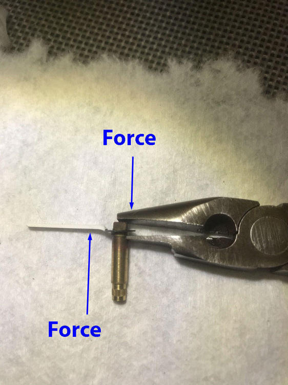
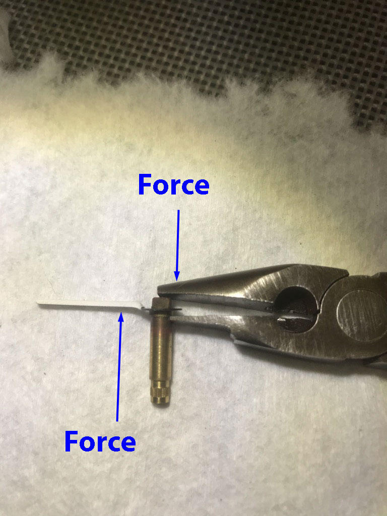
 I should mention that the plires,used as a puller, is only to break the surface tension of the corrosion between the clock hands (Tin) and the clock shaft (brass). Once you get the hand(s) to slightly move you can remove it with your fingers. Also, the plires are used to remove both clock hands. I know that some hands can seem like they are welded on. In that case you can use 1/2 drop of "Blaster" penetrating spray and let it sit for a couple of hours (don't get any on the clock face). Just before you try and remove the hand apply heat from a hair dryer or heat gun and it will let go. Also, Blaster is the best stuff on the market and it penetrates all rust. I've remove many rusty exhaust manifold bolts / nuts that normally would break. "Blaster" and heat works every time.
 -
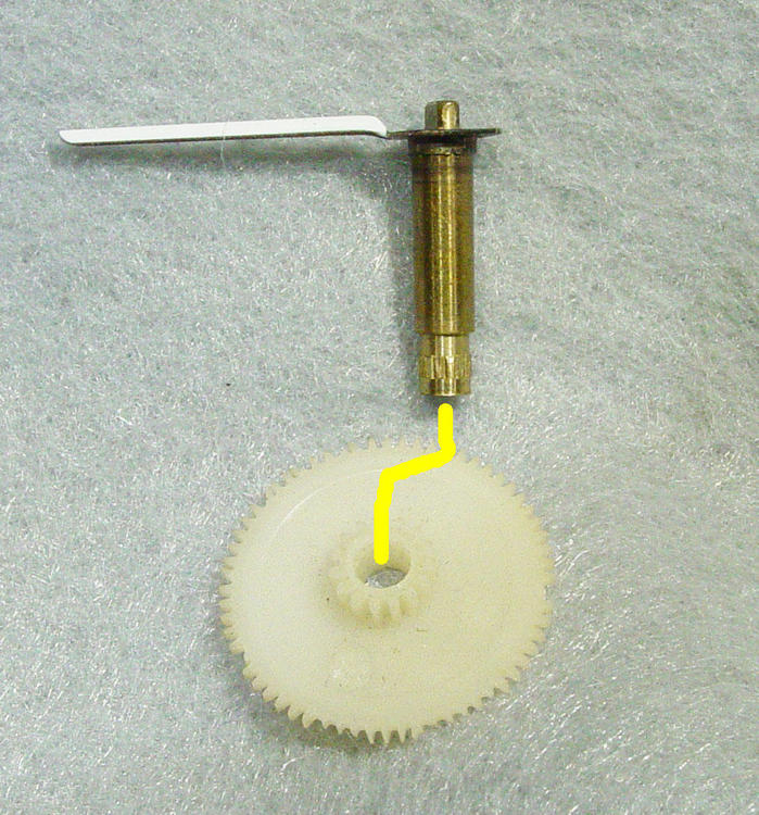
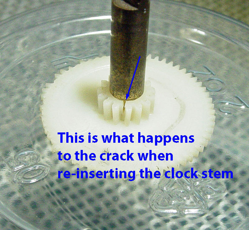
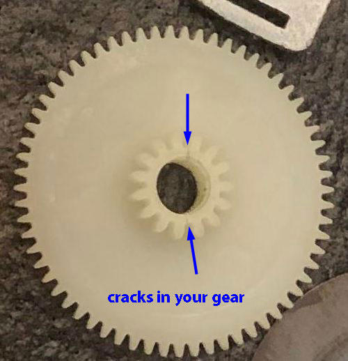
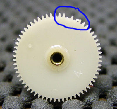
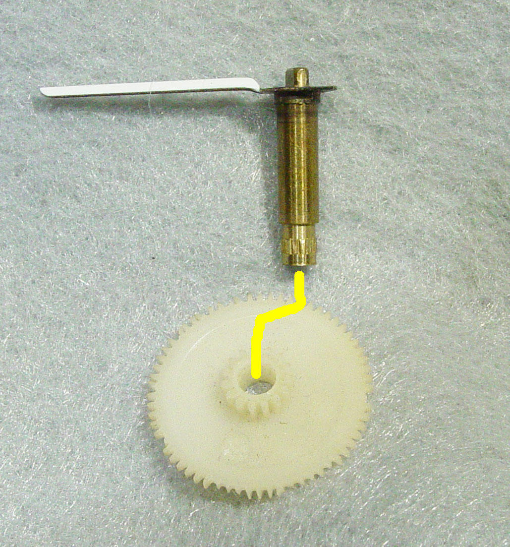
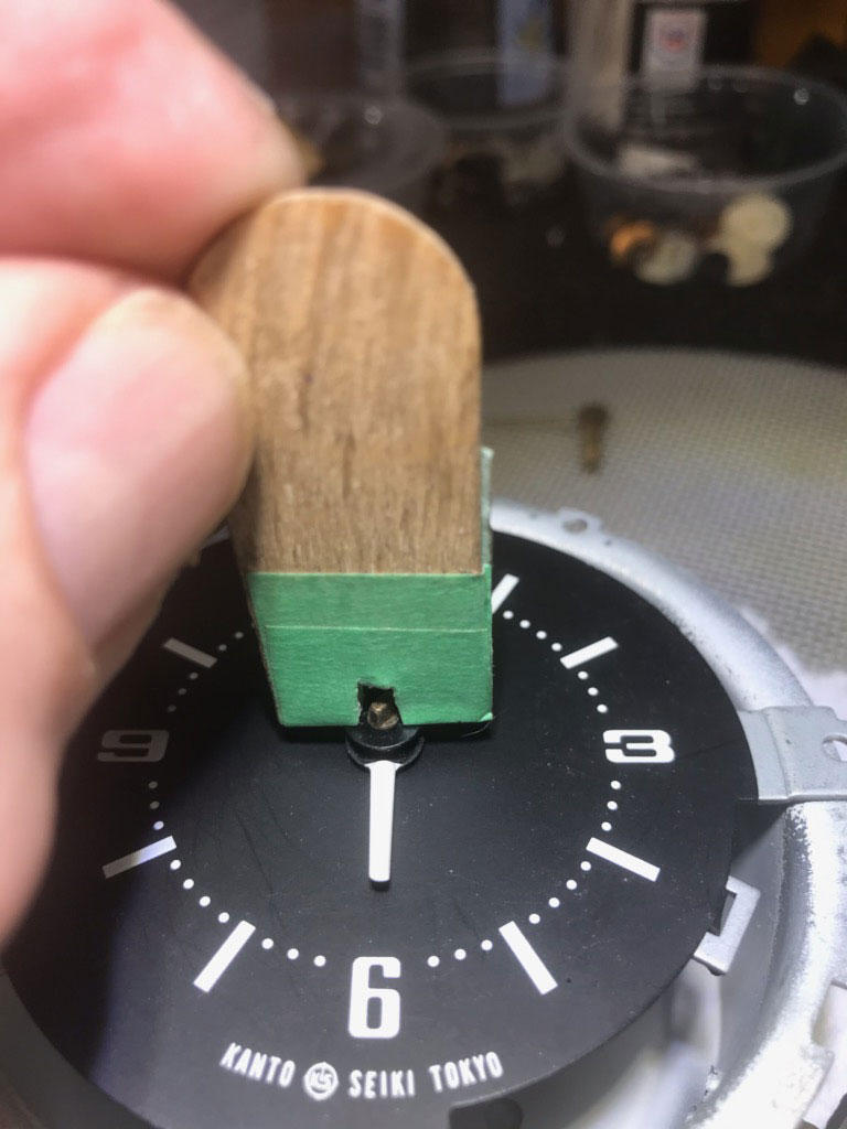
When I mentioned removing the clock through the glove box I was referring to the 240Z. I always remove the 280z clock through the vent under the 3 gauges. You remove 8 screws and the clock slips right out. You didn't mention , but is your clock keeping good time? The way to adjust the clock hands is you have to remove the minute hand form the clock shaft. If you remove the shaft from the main clock gear and reinsert it you can damage the main gear. I enlarged one of you photos you posted and I believe there are two cracks in your main gear. The reason you shouldn't remove this shaft from the gear is the end of the shaft is knurled and there is an interference fit between the knurled shaft and the Nylon gear. The shaft is inserted in the gear when it is removed from the injection mold. The warm nylon conforms to the knurling and locks the shaft to the gear. Fast forward 40 plus years and the Nylon becomes brittle. You stress the Nylon when you remove the shaft and potentially crack it. The nylon is really stressed when you reinsert the knurled shaft as the knurling will not go back to its original position in the gear. When I say stressed it cracks and the teeth on either side of the crack separate.This changes the spacing between the two teeth and the mating gear can lock up or slip. Not much you can do now, but I wouldn't put additional stress on the shaft by pulling it out. If you want to get closer with your clock hand alignment you need to remove the minute hand with a puller that doesn't apply stress. Using the credit card and screw driver method is what pulled the clock shaft out of the gear. If you look at the photos you will see the puller I made. All you need is an old pair of needle nose pliers and a bench grinder. To insert the minute hand back on the shaft what I use is a tongue depressor(modified). As far as the rubber gasket goes just flip it over 180 deg and use it. The only function it serves is to push the bezel /lens out 1/8 inch for the alignment of the clock set knob. None of the mechanisms are hermetic. If the 240z clock mechanism was hermetic the clock would last years longer. You can remove the lens, but you risk damage to the lens and the bezel. Mask off the bezel with painters tape and polish the lens. The polish I like is Flitz, Semichrome, and Brasso. They all do a good job on the plastic.

-
It looks like you are right on . Of course it's hard to tell from the angle of the photo. If you set the hands to 6 o'clock it should look like a straight line, is it? You have to remember that the clock hands are very wide and there is gear backlash. The best you can set the time for is + 10-15 seconds. Trying to manipulate the gears once assembled is the hard way to go. Same thing like removing the 240 clock. Why access the clock by removing the heater controls when you can go through the glove box!
-
If you take the clock apart in the future I can tell you how to align the clock hands.
-
Good for you. You are extremely lucky that all the teeth on the gears are in tact. Usually 98% of the clocks I see have broken gears. Report on how the clock performs over the 12 period.
-
Don't use oil. It will not help and only cause problems. This is not a grandfather clock which needs TLC and oil yearly.
-
Your are talking about two different clocks. Before you replace any components you need to test the coils or you are wasting your time replacing components. With the circuit board installed power up the clock and watch the moving magnets on the clock wheel, it should move ever so slightly. This indicates the coils are good. If no movement then one or both coils are bad. The OEM clock components should be replaced with the exact component values or you will change the clock timing. Soldering around the coil wires is very tricky and I mean VERY tricky. You can destroy either coil by over heating.The wires are 2mm, coated and don't like to be re-soldered. Replace all the caps and the transistor. The second clock which you described is a kanto Seiki quartz. I have never seen an electrical component go bad on this mechanism, it's usually mechanical. The plastic gears have stripped teeth, worn nylon or the toroid magnet is broken or damaged. The nylon gears and toroid are not available. I have a mold and make my own gears and NO I do not sell the gears. Stripped gears are not the root cause, but the effect of the problem. Replacing gears is not the answer. Hope this helps
-
The gears that go bad and are not available. .
-
Your clock has missing teeth on the main clock gear. When the gear train gets to that position it stops because a tooth, one or more , are missing.
-
Dave, Very nice. I've been following this thread as I have the same problem with my 75 280. I don't suppose there are any markings on the disk( had to ask)? The resistance is a good piece of data. I suspect the lead material is Tin or lead that may have been solder coated at one time. This is 45 year old technology and tin/lead is what they were using then. From the looks of the broken /deformed lead on the thermistor wire it appears to be severely oxidize -reduced. This is why you couldn't solder it. One last question. I think you have a side mounted fuel gauge in your gas tank. Were you able to remove the gauge while the tank was in the car or did you have to drop the tank? Thanks for all your work.
-
Did you measure the thermistor to see if it has a resistance?
-
I take that back, I did get it to work. Down load to desk top and then open.
-
couldn't get the video to work either
-
Thank you. Will give them a try.
-
Hey Motorman very nice plating. What is the name of the plating shop in AZ? Thanks....Ron
-
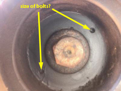
I have been trying to remove my crank pulley on my 75 280 and at the point where I install a puller to remove the pulley (mine has two). I can not determine what the thread/pitch of the holes in the pulley. It seems like a 6 mm and starts to thread in both holes, but stops after a couple of threads. Does anyone know what this bolt size is ? Thanks in advance.....Ron BTW the major bolt in the photo has been removed.
-
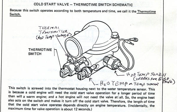
Zed, There should be 4 on a 75. The fourth is a coolant Temp switch which could be placed on the side of the housing or in the front.
-
There are several things that are not a 75. 1) The 75 only has 2 fuse links and yours has 4, just like the 77 and 78. 2) The AFM for 75 does not have a hose attached to the connecting boot, yours does. 3) All of your gauge fonts are from a 77 and 78. The Quartz clock was only offered in 77 and 78(that could have been change). 4) You have a heat shield that protects the master brake cylinder. Only came with the 77 and 78. 5) The thermostat housing has 4 ports in the front for sensors and you are only using 3 like the 77 and 78. Very odd. I have a 75, 1/75 production date, and it looks nothing like yours. If the PO transplanted everything from a 77-78 to a 75 shell he did a lot of work!
-
This is a little piece of data , but are you sure this is a 75? It would appear that you have a 77 or 78 280z. Check the drivers door jam for production date. This will make a difference if your looking for data or parts/ location. BTW very nice car.
-
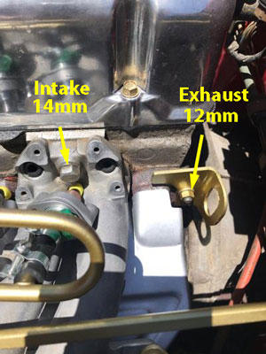
Ok, couldn't see the forest for the trees. What I fixed on was that the manual says" 8mm" and "10 mm". If they would have said M8 and M10 that would have made more sense. I know the exhaust manifold stud next to the fire wall can break easily (been there done that) and was worried about the torque in the manual. Thanks to all for your input.
-
Ok, I finally got around to replacing my fuel rail and a few questionable bolts and nuts. When I looked in my 75 280 service manual it says that the stock manifold 8 mm bolts torque is 10-13 ft-lbs and the 10 mm bolts are 25 -36 ft-lbs. My manifold intakes are 14 mm bolts and the exhaust are 12 mm nuts? What am I missing here? Any clarification on size and torque would be appreciated. Thanks
-
You said you had a lot of R12 to work with. I still use R12 in my 75. Where did you get the source of R12?
-
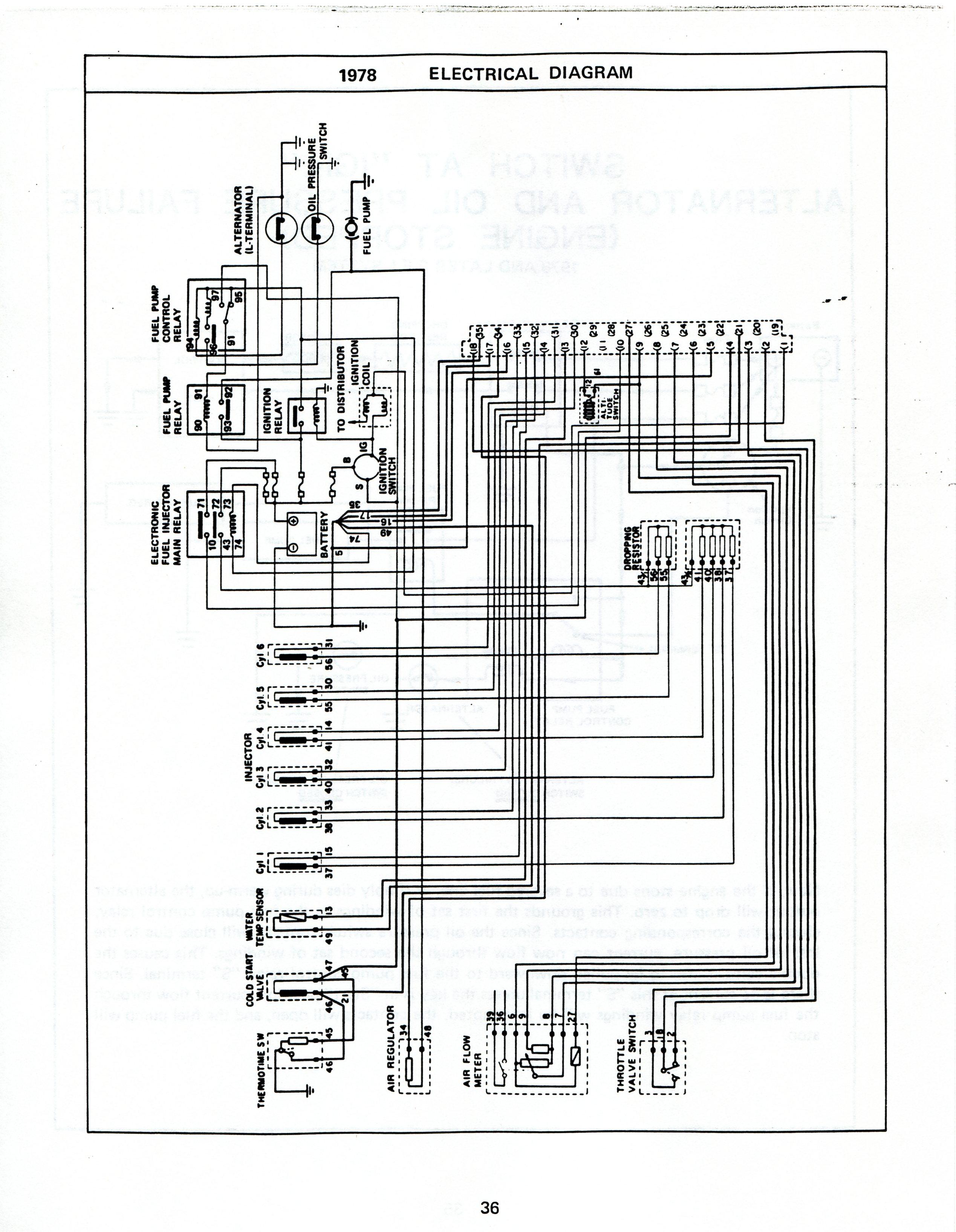
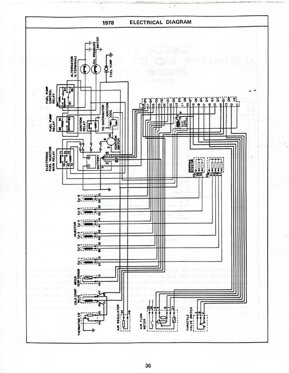
Hi Alex, Congratulations on your first project. First I think we should back up and see what year you have. I have a 75 and 75-77 FI was much the same. The FI manual you need is the 1980 version as there are changes. In 78 the FI relays were located under the hood according to the FI manual and they show 4 on the schematic just like in your photo . Are you sure the car is a 77? Did you look at the production date on the jam of the drivers door? If this is a very late 77 it might have the newer 78 relay upgrade. Maybe some one of the 77-78 owner could chime in? Look at the items I've enclosed and if you have the 4 relays then the schematic could help you track down the wiring, it's for a 78. I have seen both FI manuals somewhere free to down load , but if not I have copies of both you can have. It's almost essential to get a Datsun 280z Service manual as it is really the best for an owner to have.
.thumb.jpg.0a9797b47bbf15115048b5d881379358.jpg)
.thumb.jpg.201cf7030f7c0cfbc3b508882e389524.jpg)
-
Captain, Yes, I do have a signal gen and I found my Tach extension harness. Now if I could only find the 2 tachs I have. All this searching I found parts I didn't know I even had.
-
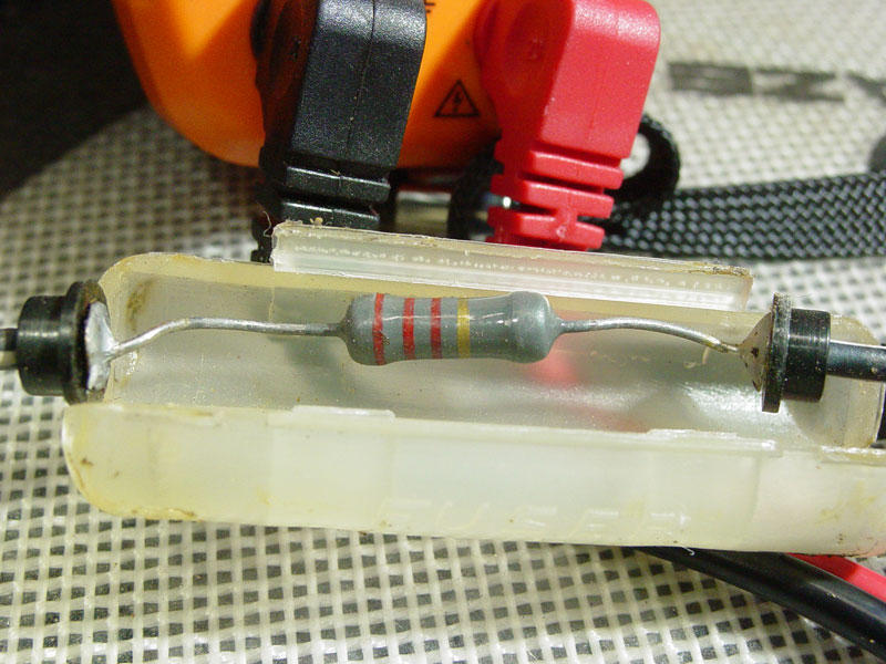
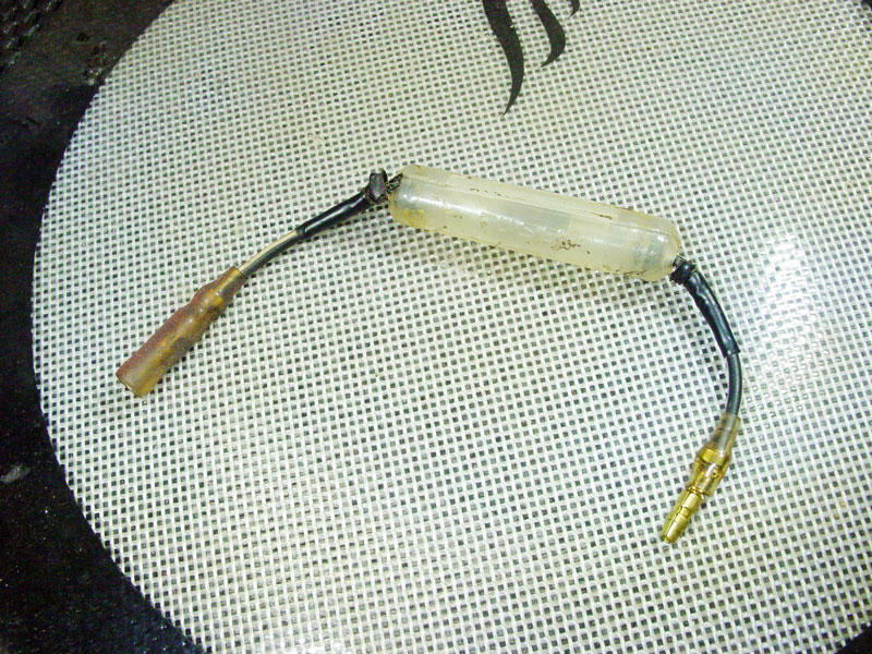
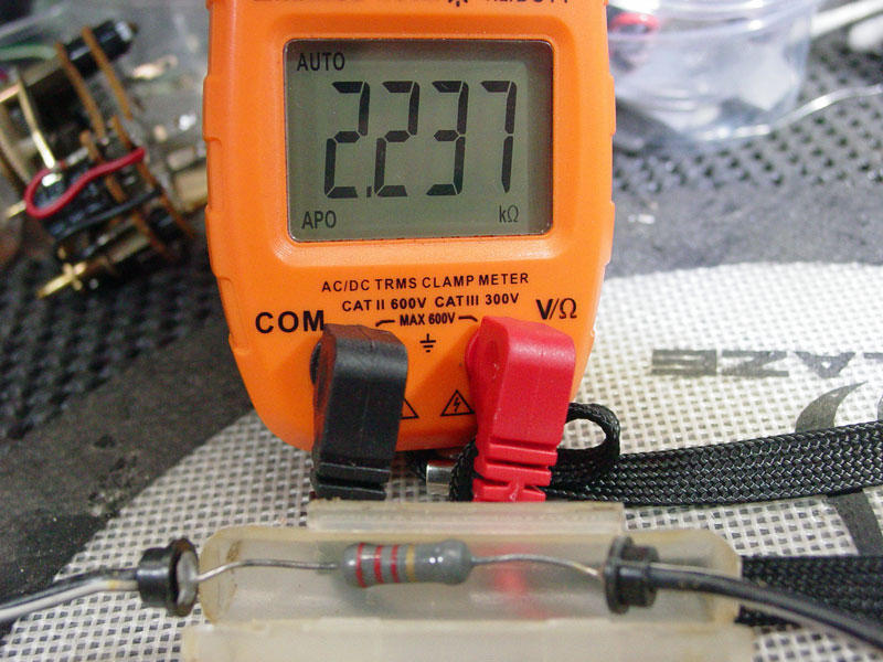
Hey zKars, I found my tach resistor on my 75 280z . It was very close to where yours is, but my resistor holder is completely different. It would appear to be the old style FUSE holder. I guess in Jan of 75 that's all they had! My resistance (2.237K ohm) is close to yours and it looks like a 2 or maybe 5 watt resistor. Hard to tell anymore. The connectors are good , but I like all connections crimped and soldered. Just another something to do.


.jpg.9830ecbbfc082638e37c9f547f8e9a87.jpg)
.jpg.3ce2245362b35505f7fe8fc66af76cec.jpg)