.JPG.cfcada9cf1c1b502df3f5f2f2ca3ff36.JPG)

SteveJ
Free Member
-
Joined
-
Last visited
Everything posted by SteveJ
-
 Did you confirm that it is on the compression stroke? Did you reorient the oil pump & distributor, or was it oriented like that when you got the bunny ears on the camshaft on cylinder 1?
 -
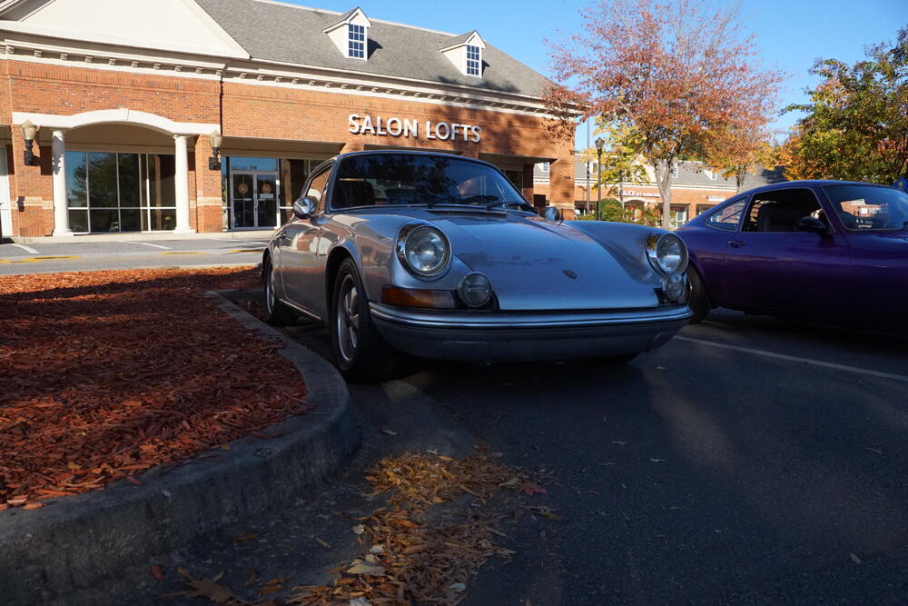
One funny thing happened while I was taking photos was that I was stopped after taking a picture of the Porsche below. The owner wanted me to feel his headlights, and it wasn't even a dirty proposition. As I walked over to his car, I said, "Oh, do you have the concave headlights from Cibie?" It surprised him that I figured it out. I let him know the concave Cibies were valued in the Z car world. It's great when different parts of the car loving universe can intersect.
-
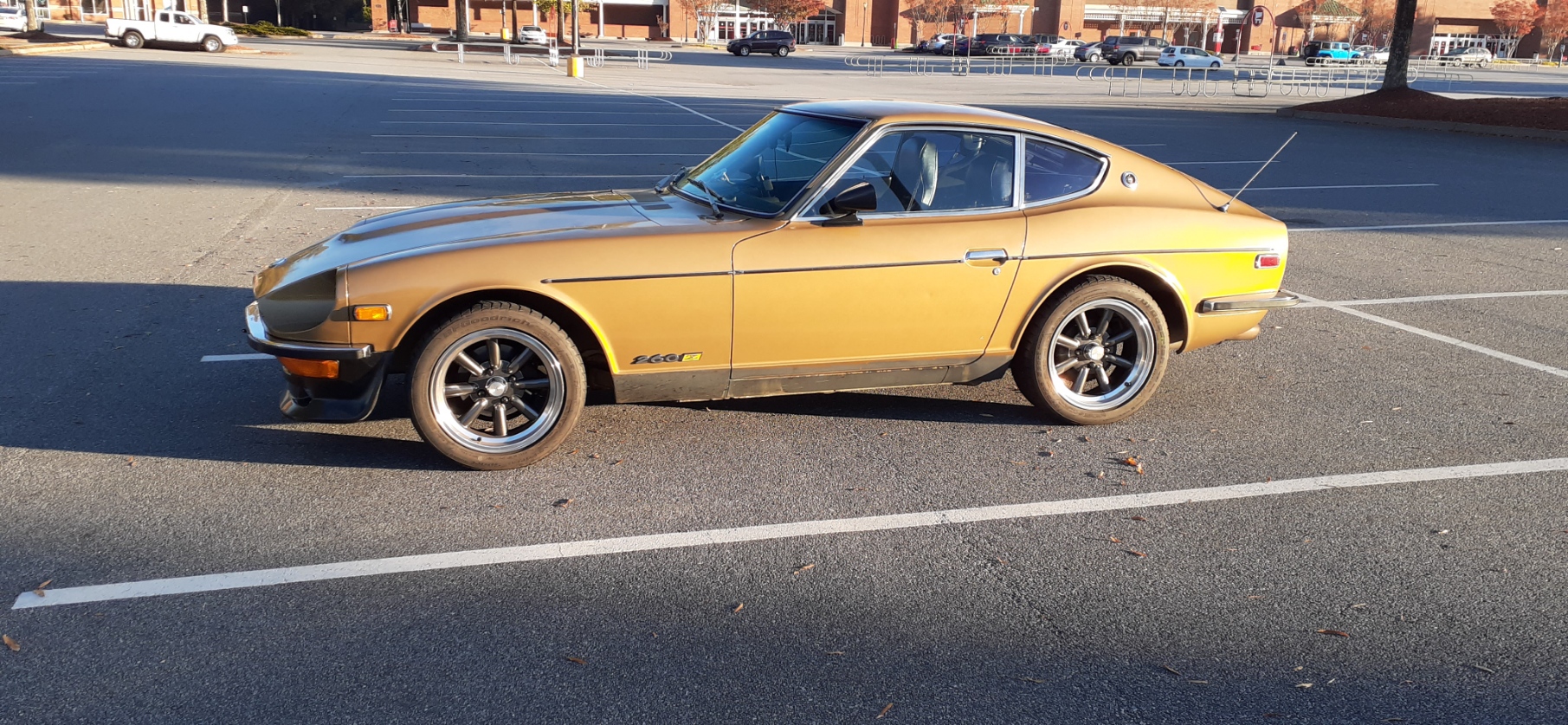
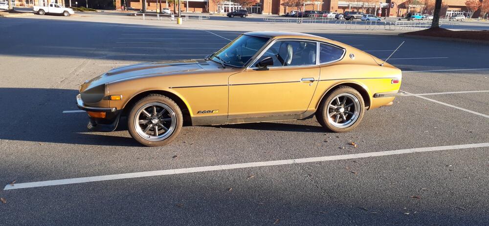
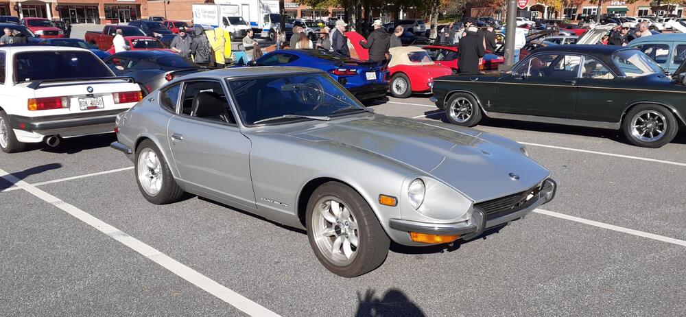
Well, I haven't been driving the Z much lately, but the weather looked good for the Worship meet today. Worship was started by people who thought our local Caffeine and Octane show was getting overwhelmed by non-car people. I like going because people don't care that I don't have a show car. They are more than interested in the modifications I have made. It was cold starting out, and it took a while for people to show up. There were only 2 other 1st gen Zs there, plus a 350Z. One of the highlights for me was when a guy in a Cayman drove up with his German Shepherd. As soon as he opened the door for her, she made a bee-line straight for me. She was such a sweetheart. It was a good sized crowd eventually. Just to prove I didn't have the only Z there, here is my friend's Series 1.


-
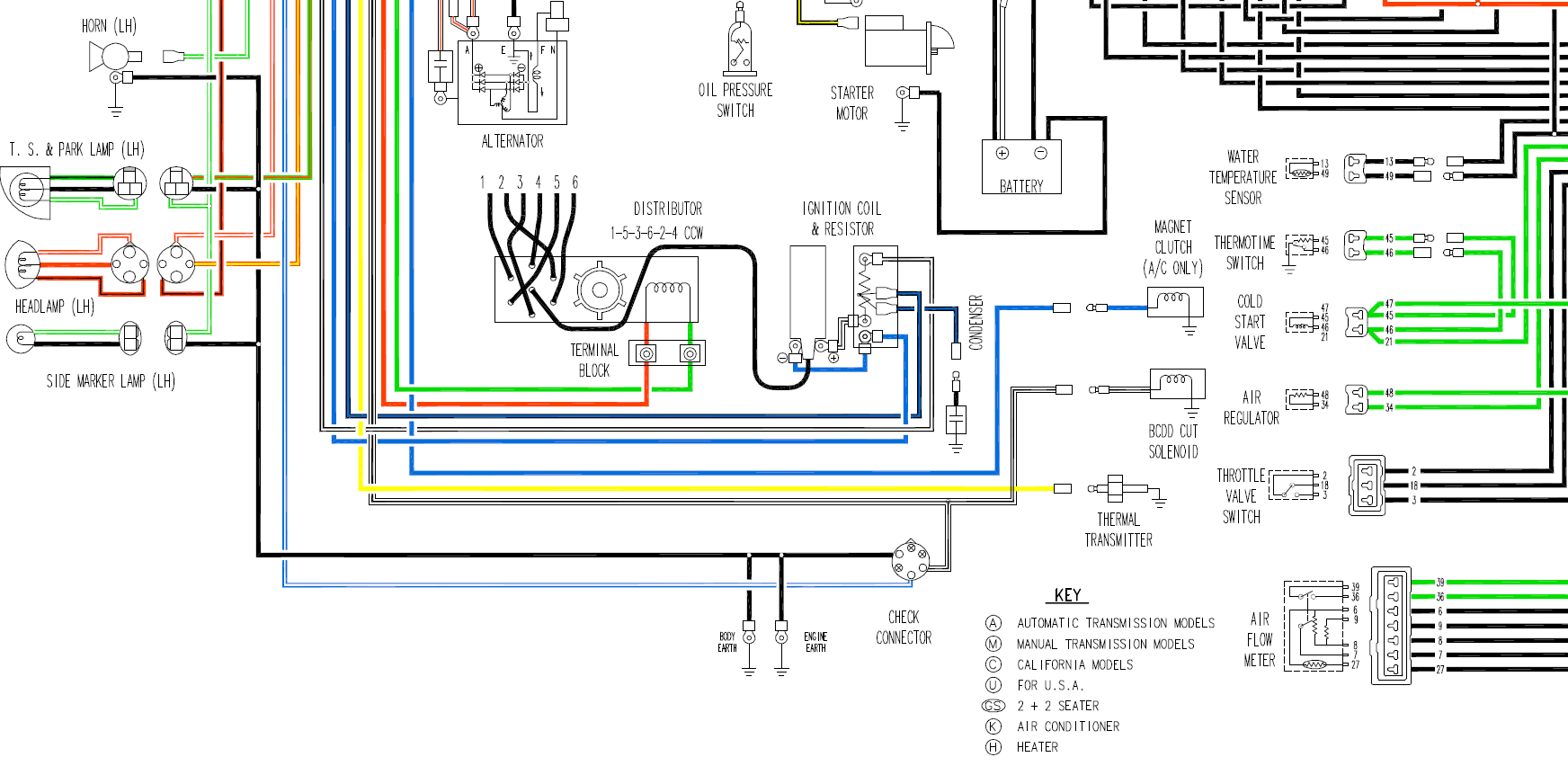
I appreciate your willingness to go back and test. Let's look at the coil and work back. Fortunately, it's not that difficult to trace. For stock wiring there should be a white/black wire from the coil to the ballast resistor. There is a black/blue wire attached to the ballast resistor on a different terminal. The black/blue wire goes to a 3 wire/4 position plug and through the engine harness to connector C-5 where it stays black/blue going through the dash harness. The black/blue travels over to the ignition switch where it is energized when the key is in the start position. So what could cause the voltage to drop? The ignition switch could be wearing out. There could be corrosion at one of the three connectors There could be a bad connector at the ballast resistor or failed ballast resistor. So what can you do to test? Measure resistance at the ballast resistor between the white/black wire and black/blue wire. Alternatively, you may want to test the voltage to ground at the black/blue wire at the ballast resistor with the key in START. If it's 12+, then it's probably the ballast resistor. If it's low, you know it's before the ballast resistor. Visually inspect the connectors. If they need to be cleaned, a little vinegar on a q-tip can clean off corrosion at the connectors. Disconnect the connector on the back of the ignition switch and test the resistance with the key in START between the terminals where the black/blue wire and the white/red wires would go.
-
Check the voltage at the battery while cranking. I'll bet it's pretty low, too. You don't say how old the battery is. Maybe you did earlier, but I'm not going back to see. The plates could be sulfated, they can still have adequate voltage while sitting, but they don't have the surface area for the electron flow needed during cranking.
-
For the Crane, red goes to coil positive and yellow goes to coil negative. The black/white wire that is hot when the key is in Start or On is on the coil positive. Why is the green wire on coil negative? It would either go to the distributor or to the TIU. Neither one is in service, so it could be pulled off the coil negative. Has the TIU been disconnected? It doesn't work with your (@mayolives) setup anymore.
-
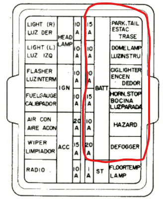
Here are some suggested steps. Some of these I have already provided. Disconnect C-9 and check resistance on the alternator side of the black fusible link to ground. If the resistance went up, go to #5. If you still have low resistance, disconnect all of the white/red (W/R) wires (including the one to the condensor). Measure resistance at the fusible link again. If the resistance at the link went up, check resistance to ground at your alternator where all of the W/R wires were connected. Otherwise, you likely have a problem in your wiring harness. With C-9 still unplugged, measure resistance from the (W/R) to ground. You can do that at the fuse box. Just select the right side of any of the fuses I circled. If the fuses were in the fuse box with high resistance, remove the fuses and measure again. If the resistance is still high, unplug the ignition relay and measure again. Record your results, and also take photos. As for the wiring at the coil, is that an I91, E92, or E93 coil? I recognize the red, yellow, black wire bundle as probably being from a Crane ignition system. It makes me wonder what distributor is in the car, since the Crane optical trigger was designed to replace the points, not a reluctor.
-
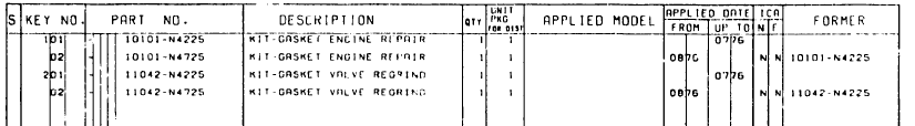
Not those of us who supported the site way back when and bought the CD of the parts catalog. 😉 I also have a paper copy...just in case.
-
I double checked with the parts CD that @Mike used to sell on this site. The text isn't very clear, but it looks like the dates shown on CarPartsManual.com are not correct.
-
I'm not sure what you mean by Carpartsmanual.com not having the actual part numbers. I tried the numbers listed at CourtesyParts.com, and they came back as NLA.
-
-
I dunno. That connector on the yellow wire looks like a deformed female bullet connector to me, but I can't blow up your photo to confirm. The only other yellow wire that travels much in the engine bay is the neutral going from the VR to the alternator. It wouldn't be roaming around the driver's side of the engine bay, though. I would not be surprised if you don't currently have a wire going to the temp sender. Yellow was used for this wire in all of S30 diagrams that I have seen.
-
From the wiring diagram: Yellow - Temperature gauge sending unit - Does it have a female bullet connector? White/Black - BCDD Cut Solenoid - Does it have a female bullet connector? I see the same two grounds that you see. However, you're not showing the ends of the wires, so that limits what I can figure out.

-
The connectors were made in Japan. I would be surprised if you found a source in the EU. The factory service manual (FSM) has most of the connectors drawn in the EE section. Some of the connectors, such as for the 74 and later, are essentially not available (headlight connectors, distributor connectors, voltage regulator connectors, and even many of the harness interconnections). If they are available, no one has made a source widely known in this forum.
-
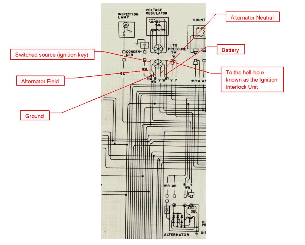
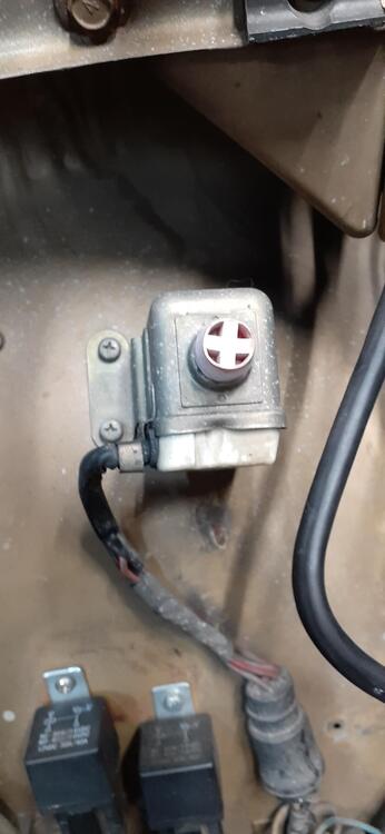
The "relay" is the voltage regulator. The W/B wire is for the field. It should inject current into the alternator when the voltage is low. A failure to produce an output from the alternator could be a problem within the voltage regulator or the alternator. What makes you think I don't like that grotesque abomination called the Interlock Relay Unit? Have you ever buckled up an inanimate object in the passenger seat because the car would not start otherwise? Seatbelt interlocks came from a push by Ford to make itself look good to the NHTSA about getting people to use their seatbelts more. While Ford had already designed and debugged their system, the NHTSA mandated the implementation of a seatbelt interlock for all cars in the 74 model year. With the relatively short notice most automakers implemented the rules poorly. The NHTSA quickly retired the rule. Here is some reading on the subject: https://www.allpar.com/threads/the-return-of-the-seat-belt-interlock-crazy-rule-or-money-saver.236643/. People found ways to defeat these systems because a faulty interlock would make it where you couldn't drive your car. There is an emergency button under the hood on the passenger fender. There's a picture below. In its early life, the button was red. It's an annoyance to have intact, but it won't affect charging.
-
Does your meter autoscale? A reading of 1.84 ohms would translate into 7A of current. That won't blow a fusible link, but that's a strong drain. Did you make sure all of the switches were off? ( @Captain Obvious I beat you to the question. 😉 ) By outside front, I'm going to assume that is the black fusible link in the picture Capt posted. That has 3 connections at the alternator: Condensor Battery terminal Sense terminal Make sure all three are unplugged. It also runs to the ignition relay and fuse box. It feeds a bunch of circuits. You can isolate the alternator from all of those circuits by unplugging connector C-9 and taking the resistance measurement again. C-9 is a 6 wire connector in the passenger footwell with the other engine harness to dash harness connectors. By the way, testing an internally regulated alternator that I have handy, I saw 2.2K ohm from the B to E terminals.
-
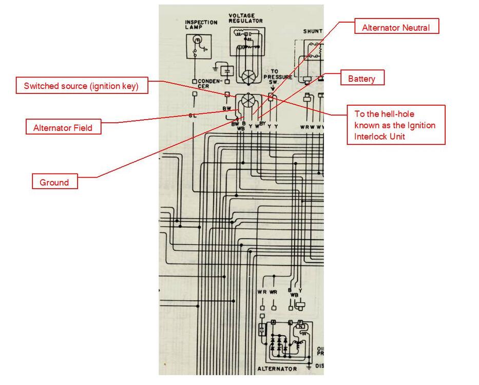
So when the key is on, the B/W wire has 12VDC. The Y wire will have about 7 to 8 volts with the alternator turning (full alternator voltage divided by the square root of 3). The B/Y wire is just to provide a ground to the hell-hole known as the Ignition Interlock Unit (Boo! Hiss!) Chances are that it has already been bypassed in your car. Note that in other parts of your wiring, B/Y is 12VDC when the key is in start and goes to the Interlock Relay (Again, Boo! Hiss!). B is your ground. W is your battery voltage and goes to the alternator through the WB wire when the appropriate contacts are closed.
-
That lines up pretty well with what I was reading on the power supply.
-
I actually did that once before I tore apart a fuel gauge to look at it. I only connected the green and yellow wires to a 12 volt source (2 lantern batteries in series) without a load. The gauge went to full, and I can't remember how long I had the circuit completed. However, later on the gauge would not register at all. This was 10 years ago before I started studying the wiring diagrams to death. It was interesting to see in the video how much the current dropped after the first heating coil came up to temperature and started operating the voltage regulator. Mind you, that was on the second run of the day after I verified I had a working circuit. I just ran a test. It took about 7 seconds for the VR to come up to temperature with an ambient temperature of 64 degrees F. I don't really want to see what the power supply ammeter reads without the VR just in case I'm right that it could burn up the gauge.
-
Thank you for the correction. What I wanted to show most in the video was that the voltage regulator should be connected while testing. I have seen in the archives about people testing the fuel gauge out of the car, and it failed when they only connected the green and yellow wires (no wire from black to ground) for testing. The gauge I used was one I purchased about 10 years ago and never tested. Fortunately it is a good gauge. Again, when testing, don't forget to connect the black wire to the negative of your power source.
-
Or you could put a short bolt in there with a fender washer on each side. That would hit the plunger on the switch.
-
So I set up the gauge with my power supply and a variable resistor. It's interesting to me to watch the power supply ammeter while I'm doing the demonstration.
-
You didn't see something like this on your brake pedal?

-
You'll need to find a longer bolt. The part is 46518-21000. It is NLA. I'm surprised that Steve Nix hasn't made a reproduction. @nix240z Is this something you might be making in the future?
-