.JPG.cfcada9cf1c1b502df3f5f2f2ca3ff36.JPG)

SteveJ
Free Member
-
Joined
-
Last visited
Everything posted by SteveJ
-
 Eastern Beaver Here: https://www.hi-1000ec.com/product/1139 I have used both places.
 -
I was just following @Zed Head's reasoning to a possible logical conclusion.
-
I found this on someone's car about a year ago. Cylinder 2 was reporting zero compression. The valve was mis-adjusted and the lash pad eventually turned on its side.
-
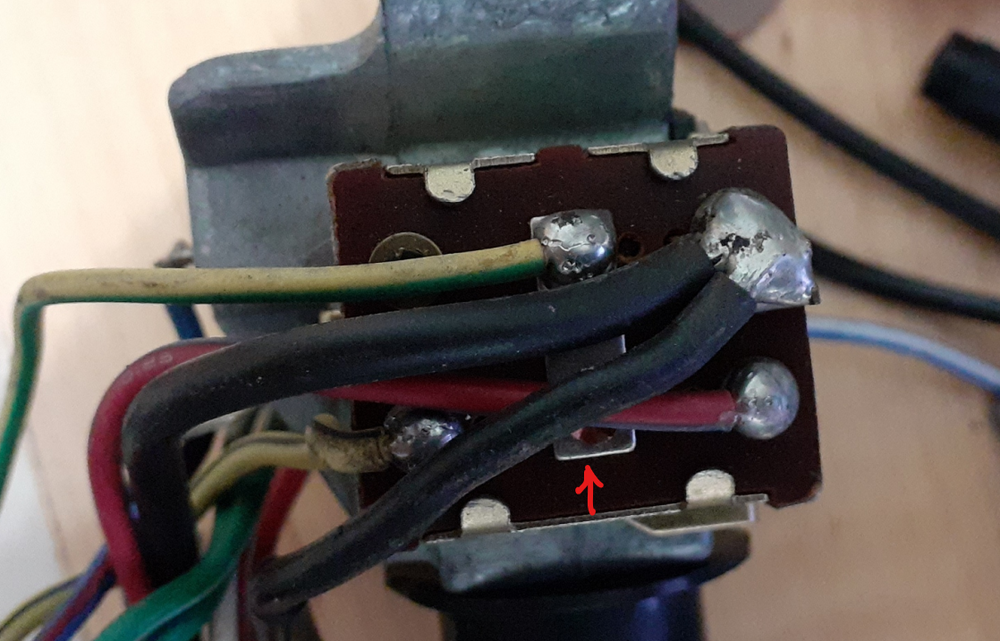
By the way, here is a picture of the switch assembly with the wires. Note the jumper across the middle terminals.
-
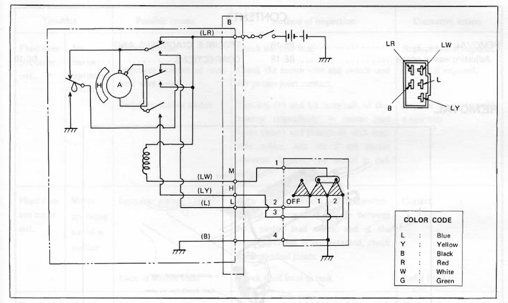
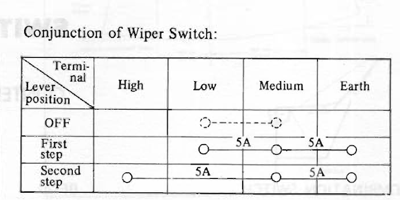
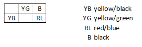
There are two basic sources of confusion with the wiper circuit. How does the circuit work? Where does Nissan explain it? What is the actual wiring? In looking through the BE section and supplements for 71 & 72, it has this rather confusing diagram. In Off, the L & LW wires are connected and ungrounded. When the switch is in 1, the LW and L wires are grounded. The LW wire is the ground for a relay that causes the motor to spin in the proper direction. The L wire is the ground for the low speed. When the switch is in 2, the LW wire is still grounded, and the LY wire is grounded, too. The LY wire is the ground for the high speed in the motor. The 72 BE section also has a truth table that backs up my observations. I am not sure why they show a dotted line connection between the L & LW wires when the switch is in off. From testing, the terminals are connected and ungrounded as I said earlier. Testing the switch operation: Disconnect the negative on the battery. Remove the clamshell from the steering column. Remove the headlight switch. You should see a switch assembly on the bottom of the headlight switch. I looked at several in my collection, and the wire colors were consistent. (see below) Set your meter on resistance. Have the wiper switch in OFF. Test YG to YB. They should have continuity. B should not have continuity with any other wire. (For testing, I put the probes on the solder joints on the switch assembly. Put the wiper in Low. Test B to YG and B to YB. Both measurements should be 0 ohms or close to it. Test B to RL. It should have a large number or OL, depending upon how your meter shows high resistance. Put the wiper in High. Test B to YG and B to RL. Both measurements should be 0 ohms or close to it. Test B to YB. It should have a large number or OL, depending upon how your meter shows high resistance. Report back with your results.
-
I should clarify. I haven't driven more than 1 hour in the dark in any given drive. I have driven in the dark plenty of times with these bulbs without issues.
-
I have used the Auxito bulbs for a couple for about 3 years now. I don't believe I've driven more than an hour in the dark, either. As for flicker, I haven't noticed it in either of my cars, and I haven't heard of any complaints, either.
-
I would suggest putting an open barrel ring lug terminal on that wire. It will last longer. https://www.amazon.com/Terminal-Connerctor-Terminals-Connectors-Assortment/dp/B08GFJY4NY Even cheaper: https://www.amazon.com/Copper-Terminals-Connectors-Barrel-Electrical/dp/B0BN6335H7
-
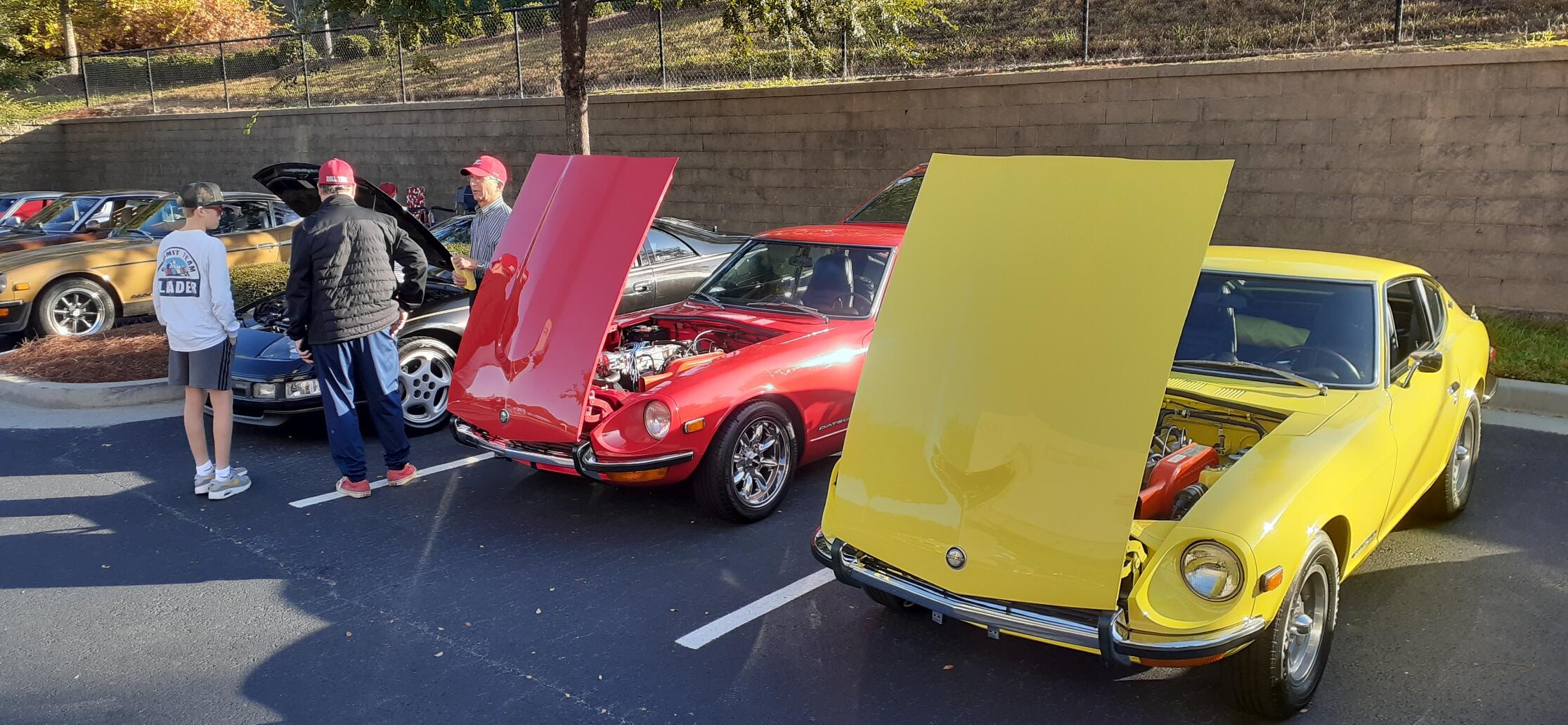
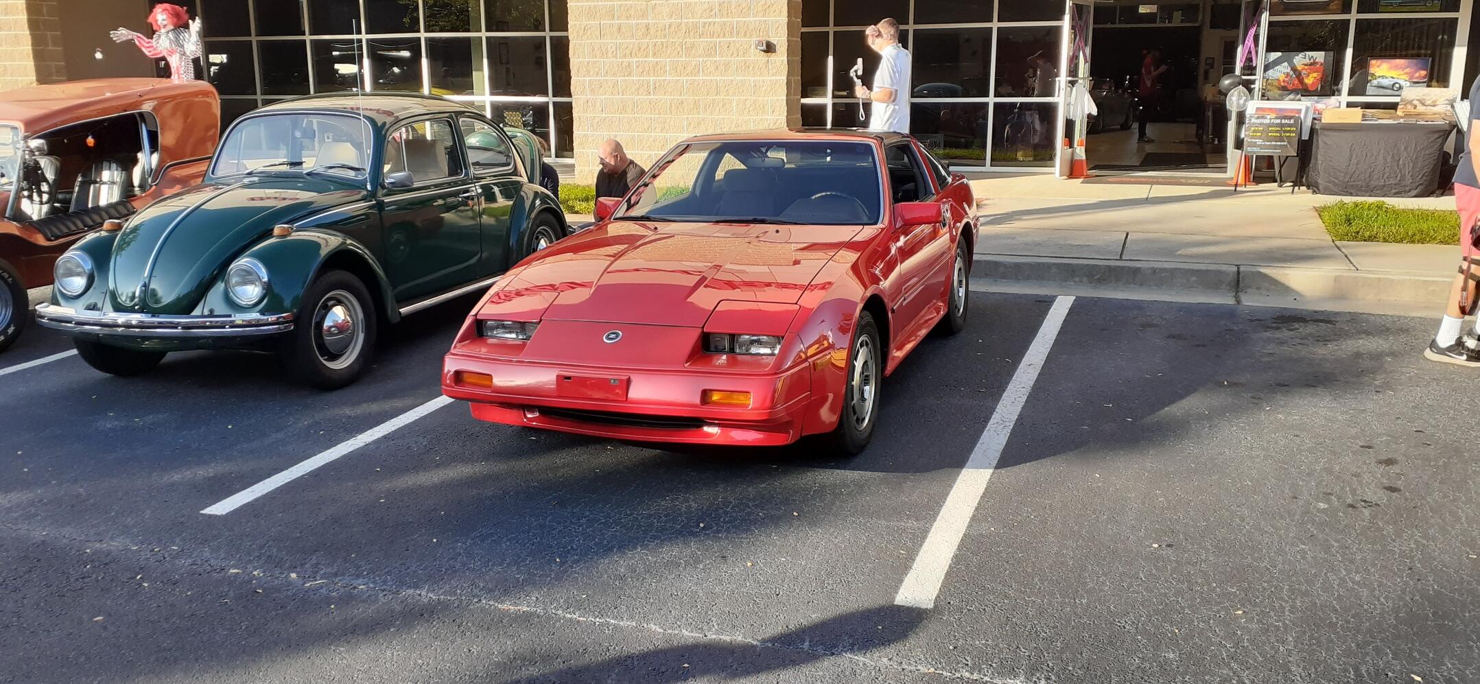
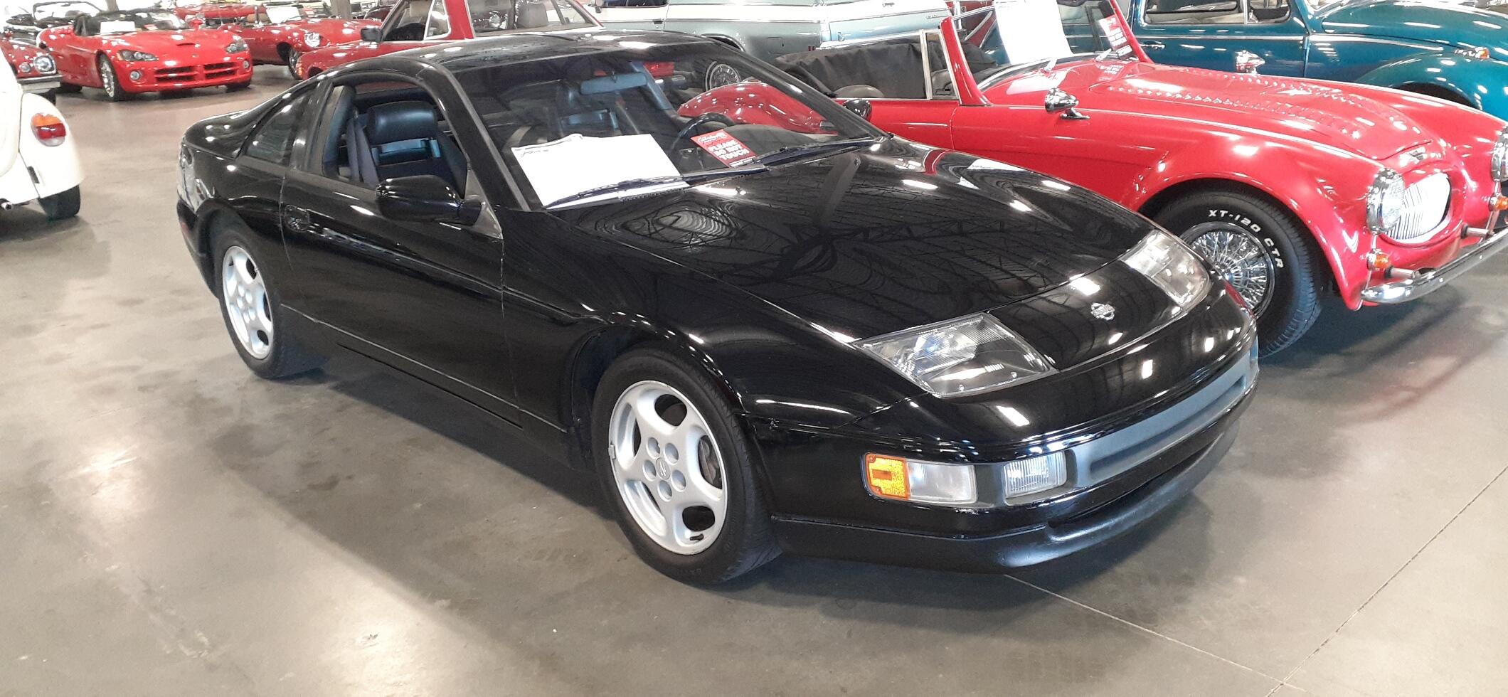
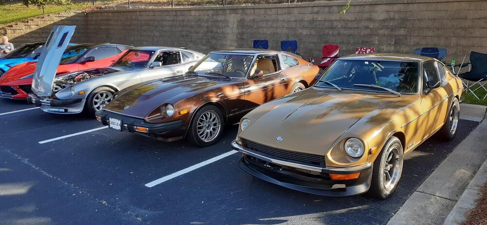
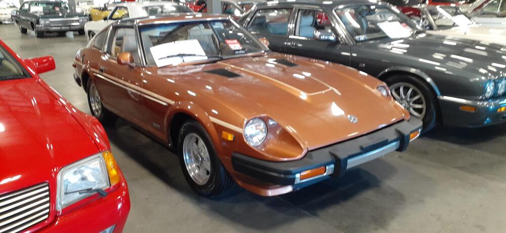
It was a gorgeous day for Trunk or Treat at Caffeine and Chrome. (If you have a Gateway Classic Cars near you, you might want to go to Caffeine and Chrome. There are 21 locations scattered across the US.) The wife passed out candy to kids, and I got to look at cars & chill. The weather is still warm (through Monday) around here, so it was an ideal day to go for a drive and hang out at a car show. I also ended up helping a Z friend. He said he was parking and felt the steering column become loose. He found a bolt on the floor and put it back in, but he said it still felt floppy. I looked at the car and found the other 3 bolts were barely on. Fortunately I had my travel tools with me, so I got the other 3 bolts nice and snug. There was an S130 & a Z32 on consignment there, too.


-
Here's the video:
-
I'd say that's less like a shameless plug and more like a helpful offer.
-
D'oh, I discovered an error in the list. Go back and look at it again. I noted what I changed. @HusseinHolland
-
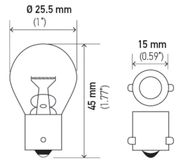
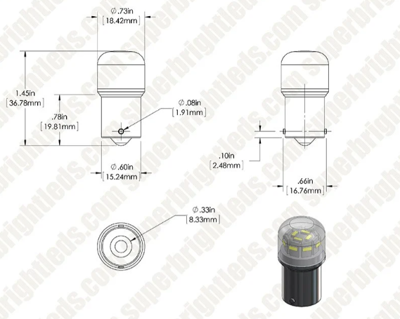
1156 dimensions: 67 bulb dimensions: The ones I put for side markers have a dome that has similar dimensions to the 67 bulb even though they are described as 1156. All of the bulbs listed are in use in my cars except for the gauge bulbs. That part number was provided by another member here. They allow for reverse polarity which is important due to a design quirk in the 260Z/280Z gauge light wiring.
-
Here's a link to my current LED list: The 240Z & 260Z didn't have the inner fender liners. Many 280Z owners discarded them, too. You can replace the headlights without removing the tires, but it's a pain if you have the inner fender liners. If you're not removing the tires, put the front on jackstands so you can turn the wheel easily, and you don't have to sit on the ground.
-
Since you need it as a daily driver, definitely change the markers and gauges to LEDs. That will help protect that parking light circuit that you already found issues with. And it will reduce the chances for future problems with your headlight switch, too.
-
Yep, you had me looking at chrome paint the other day. I watched a YouTube video where a guy was trying different chrome paints. He said he got the best results from a chrome nail powder kit from Amazon.
-
Don't hesitate to reach out to me if you need a hand. With enough notice I can drop in on a weekend to give an extra hand.
-
I hope you enjoy your night driving, @HusseinHolland.
-
When I started buying the 6.2mm & 2.8mm connectors, I stocked up on the terminals, too.
-
With as curious and ingenious as you are, you didn't explore their site? https://www.vintageconnections.com/products/2-8mm-spade-terminals
-
-
Here is the 9-pin connector: https://www.vintageconnections.com/products/2-8mm-connectors?variant=46131774095681 The best thing to do is to change out the lights on the circuit to LEDs and derate the fuse to 10A or less. I really don't think that connector was designed for over 10A.
-
That would be this one: https://www.amazon.com/gp/product/B0811GTVH2 It is not round (not important to me), and you have to add a ground wire (again not important to me). It does have an adjustable rate (something I like).
-
Okay, I was going to look at the earlier wiring diagrams next. Every year Z has some wiring nuances. So you should have the 2 wire door switch, and both wires should ground to the switch with the door open.
-
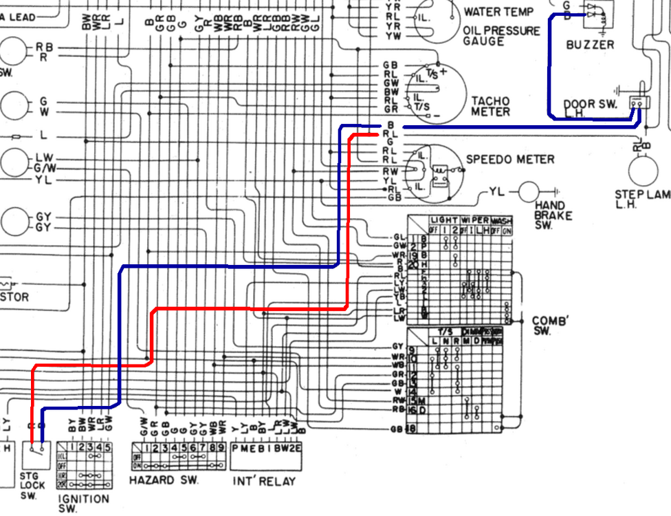
I figured that I would use the 73 wiring diagram as an example since I have a good scan of that one. The positive comes from the same circuit as the positive for the dome light. I highlighted it with the red line. It goes to the ignition switch and goes back into the harness as a black wire. (Ugh - black wire as a positive!) It goes over to the driver door switch. When the door is open, the contacts close, and that black wire connects to another black wire that goes to the buzzer. Note that the buzzer has 2 diodes as it is activated by the seat belt circuit and the key in ignition circuit. The driver side switch should have 3 wires. Two of the wires should have continuity with the door open. The third wire should ground to the switch.