.JPG.cfcada9cf1c1b502df3f5f2f2ca3ff36.JPG)

SteveJ
Free Member
-
Joined
-
Last visited
Everything posted by SteveJ
-
 That makes it pretty easy, then. Order the OEM slave from the first link I posted.
 -
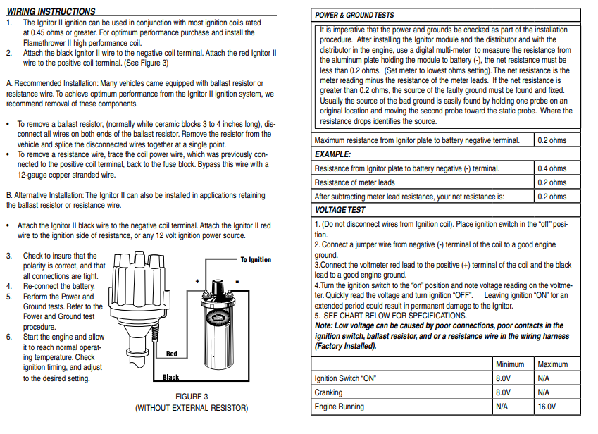
No, there will not be a lot of leftover wiring. I'm not sure what you mean by extra wires. Pertronix has the basic instructions on their website for installing the ignitor. It shows where each of the wires from the ignitor should go. Notice the specifications. A resistor in series, like the ballast resistor, will drop the voltage. The voltage should still be within specs for the ignitor. The intent of the ballast resistor is for protecting the points. The condensor at the coil also contributes to the protection. However, with the ignitor, you no longer have points. So should you get rid of the resistor? That's up to you. However, you don't just leave the wires dangling in the engine bay. The wires at the ballast resistor have to be connected together if you bypass the resistor, otherwise, the car won't run.
-
Do some research and tell us what you think. https://www.google.com/search?q=pertronix+ignitor+2+wiring+diagram&sxsrf=AOaemvLgcSyHv8UYGS5GmC6Xxz33YmNGrQ%3A1633911242656&ei=yoFjYcq7J4KHggeR8bvQDg&oq=pertronix+ignitor+2+wiring+diagram&gs_lcp=Cgdnd3Mtd2l6EAEYADIHCAAQRxCwAzIHCAAQRxCwAzIHCAAQRxCwAzIHCAAQRxCwAzIHCAAQRxCwAzIHCAAQRxCwAzIHCAAQRxCwAzIHCAAQRxCwAzIHCAAQsAMQQ0oECEEYAFAAWABg7dEBaAJwAngAgAEAiAEAkgEAmAEAyAEJwAEB&sclient=gws-wiz
-
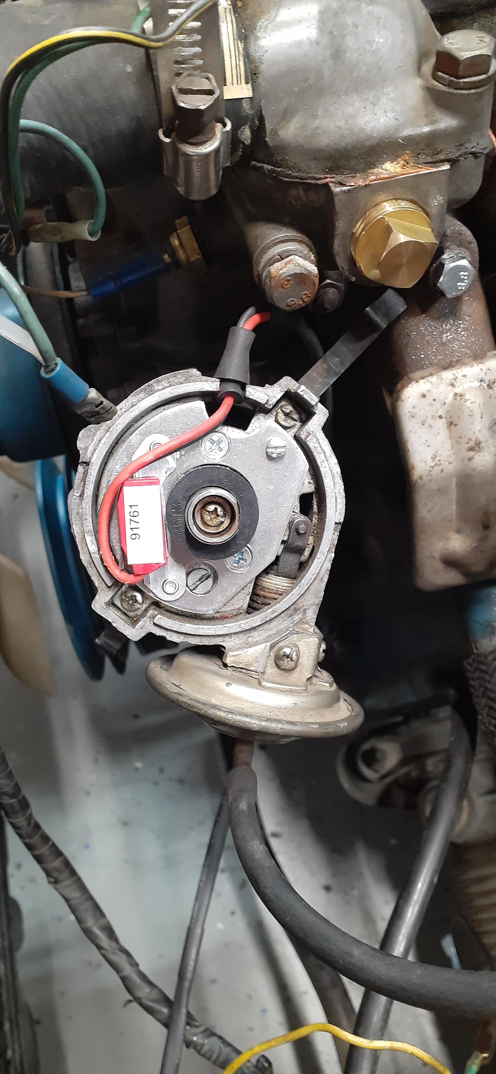
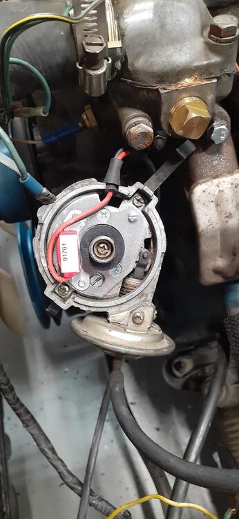
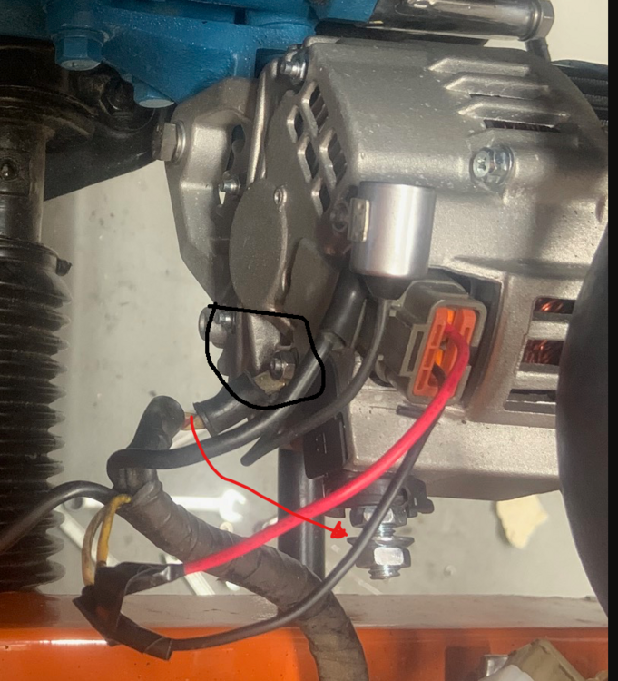
Here's a photo of my 240Z distributor with a Pertronix Ignitor 2. Background: In 1997, I replaced the points with a Crane optical ignition. It failed in 2010. I replaced the distributor with a ZX distributor in 2012. In 2020 I stole the ZX distributor to replace a bad distributor on my 260Z. When I decided to put the 240Z back on the road, I found the 240Z distributor and decided to install the Pertronix. As part of installing the Crane ignition, I removed the insulated with with the fork that you have circled in green. The female spade terminal you see at the 10:30 position of the distributor is part of the ground wire. It is not connected to anything now. Previously, I believe it was connected to the ZX distributor. My car runs fine without either of the two wires you are asking about.
-
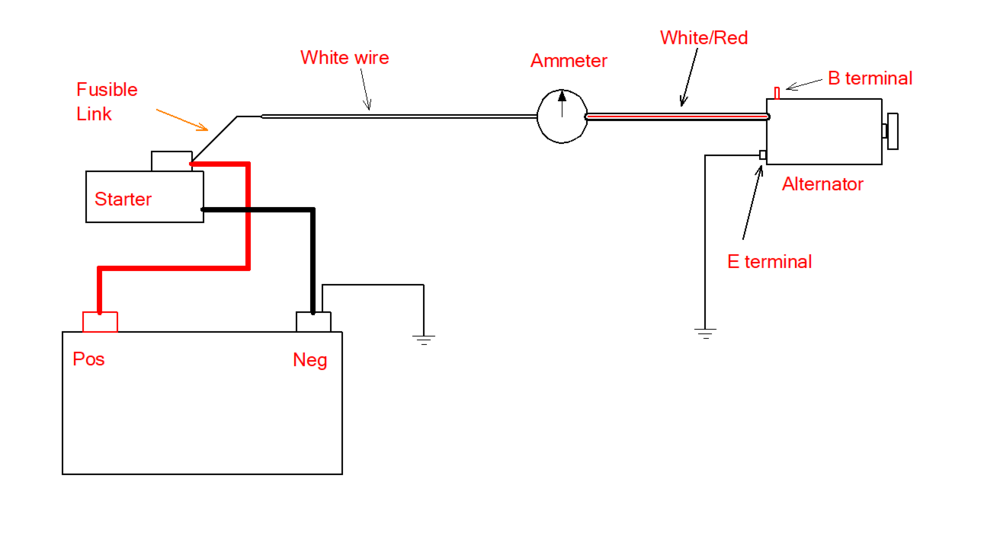
The condensor body does not have a wire. It has a metal bracket that bolts to the case of the alternator. In your photo, the ground wire is bolted to the case at the same point. Yes, the wire coming out of the condensor goes to the B terminal of the alternator along with the white/red wire. The black wire at the alternator is the ground for the alternator case. When you attached the white/red wire to the alternator case, you grounded it. That wire goes to the ammeter gauge, and there is a white wire on the other side of the ammeter gauge is a white wire. That goes down to the fusible link. I did a simplified diagram below. If the white/red wire is attached to the B terminal, it is not grounded to the case of the alternator.
-
I once helped a young man who was trying to fix his 280ZX after he attempted to jump start his car with his father's Sunbeam Alpine. That young man quickly learned the hazards of connecting jumper cables to ground when one of the cars is positive ground.
-
The forked lug on the condensor should be connected at the B terminal with the white/red wire.

-
It would probably work a lot better with white/red wire mounted to the B terminal. With where the wire is currently mounted, you have a dead short when you plug in your fusible link. At least you know what that looks like now. Don't worry. If you haven't made a bonehead mistake sometime in your life, you're not really working on your car.
-
I would posit that you have a short or improper connection in your wiring harness somewhere. My first suspect would be reversed connections at the alternator. Do you know how to use a multimeter for resistance readings?
-
http://xenonzcar.com/s130/FSM/1983/WIRING.php
-
Either the battery or alternator is wired backwards.
-
ZNationals track day is at Road Atlanta today, so I took the day off to enjoy the day.
-
Here is OEM: 70-73: https://www.courtesyparts.com/oem-parts/nissan-cylinder-slave-30620v2800?c=cT0zMDYyMC0yODUwMg%3D%3D 73- :https://www.courtesyparts.com/oem-parts/nissan-cylinder-slave-30620v2800?c=cT0zMDYyMC0yODUwMg%3D%3D
-
Or maybe both of them at the same time?
-
Did you see fluid coming out of the calipers when you bled? Did you bleed the MC?
-
Of course, we forgot to ask. What kinds of problems are you having with bleeding your brakes?
-
If the jar is above the bleed screw, the thought is that the hose between the bleed screw and jar is also above the bleed screw. If that hose is filled with fluid, you are less likely to pull air back in through the bleed screw.
-
As mentioned, press the Add Files button. You should see something like this: Press Files if it's a photo in your gallery. Select the right photo.

-
I just make sure the bleed bottle is higher than the bleed screw. I haven't had any issues with bleeding the rear brakes.
-
Let's take this apart. All three systems are on different circuits. As long as you have a good battery, and your alternator is putting out over 13VDC, voltage would not be an issue. The current for the headlights passes through the combo switch. The current for the parking lights also passes through the combo switch but through a different set of contacts. Years ago @Zs-ondabrain developed nice relay kits for the headlights and parking lights (The dash lights are on the same circuit as the parking lights.). These relay kits are sold through Motorsport Auto. Here are the links: Headlights: https://www.thezstore.com/page/TZS/PROD/12-4651 Parking Lights: https://www.thezstore.com/page/TZS/PROD/12-4652 These relay kits take the load out of the switch. Also, swapping the bulbs in the dash lights for LEDs can make them much brighter. The downside for some people (not me) is that you probably can't dim the lights unless you change the rheostat for a PWM. I am good with the gauges being bright. Now for the horns...When I was waking up my 240Z after it's 9 year slumber, I was going through the different systems and found the horns weren't working well. I ordered some new horns and a horn relay, but I figured that I would also inspect the old horns. When I removed them, I found corrosion on the positive terminal and where they bolted to the car. The latter is the grounding point. I used a narrow wire brush on a Dremel to clean the grounding points, and I wire-wheeled the positive contacts, too. I reinstalled and found I had strong horns again. If cleaning the contacts does not improve things, it could be the horn relay. Apparently, horn relays for 240Zs are becoming scarce. ZCarDepot still has OEM relays. You can get the part number from CarPartsManual.com and try a Nissan dealer up in Canada, but the US dealers show these as NLA.
-
Here are the ones I bought from Amazon. They fit. https://www.amazon.com/gp/product/B000CPCOB6 https://www.amazon.com/gp/product/B000CPCOAM
-
@madkaw is less than 3 hours from you.
-
You may want to start a new thread. It's hard to tell what diagnostics you have done with all of the non-helpful complaints from another person mixed in.
-
In my opinion, you're being a little too defensive. Also, in my opinion this thread probably needs to be locked down before it gets any more heated. @Mike @bpilati Do either of you agree?
-
He didn't say it was his switch. He pulled the photo from the site of someone who documented a restoration of a Z. He used that photo because the site creator documented what wire goes where.