.JPG.cfcada9cf1c1b502df3f5f2f2ca3ff36.JPG)

SteveJ
Free Member
-
Joined
-
Last visited
Everything posted by SteveJ
-
 I'm glad I tagged you, Cliff.
 -
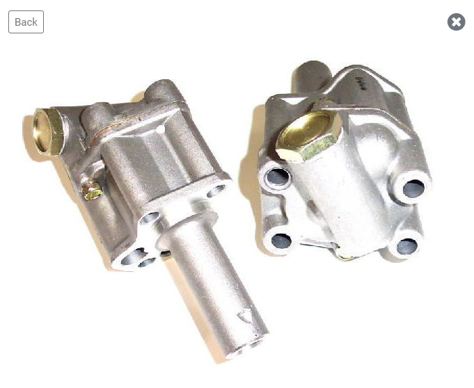
Here's an image that @Zed Headposted in a thread a few years ago: And here's one of how the oil pump shaft should look from the top before you install the distributor (courtesy of @siteunseen)
-
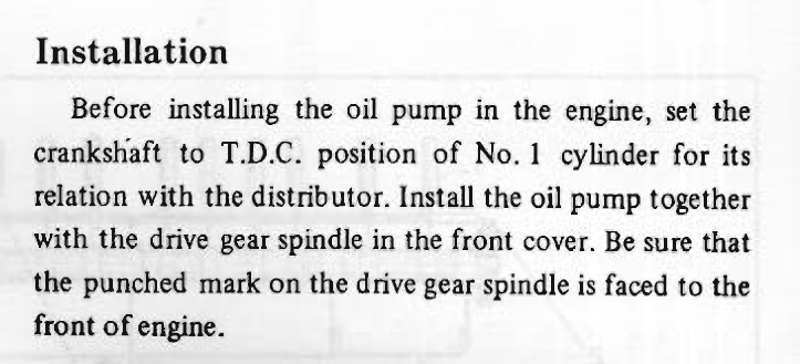
From the EL section of the FSM: Not having done that before, I would say you're looking for a mark like on the shaft in the view on the left. Or this:
-
Well, if you have #1 at TDC on the compression stroke, yes, you put the oil pump and distributor back in wrong.
-
That's probably the right stuff. I just like getting it like this: https://www.amazon.com/3-in-ONE-Motor-Oil-3-OZ/dp/B084VPH4LY It's easier to put in the carburetor with that bottle.
-
Yes, just a little bit of 20w oil. I like using the 3-in-1 20w.
-
Just let me know if/when you need electrical help.
-
@Wally Your coil wiring doesn't look quite right. For the Pertronix, the ignitor looks to be wired correctly to the coil. Just make sure the red wire is on the positive and black is on negative. There should be a black/white wire going to coil positive. The green/white wire should be connected at the same terminal on the ballast resistor as the black/white wire. Again, watch the video I linked on how to differentiate between the black/white wires. The jumper wire from the coil positive to the ballast resistor can go away once you have the other wires in the correct position. Static timing would be to check to make sure the rotor has moved just barely past the terminal for the #1 spark plug wire when cylinder #1 is at TDC on the compression stroke. (That sounds like a future video.) Unless someone has removed the distributor or oil pump and reinstalled incorrectly, about the only way for the static timing to be off by much would be if someone forced the rotor onto the distributor shaft in the wrong orientation. That's a challenge, but I've seen some people try. From your video I can tell you have a very weak battery. Make sure it is fully charged before you try again.
-
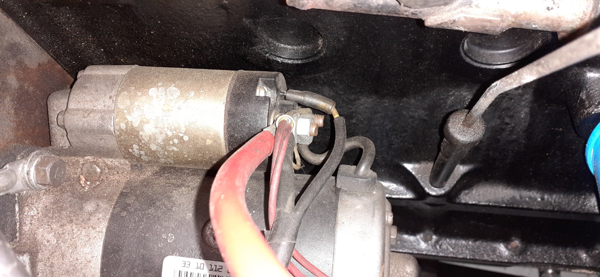
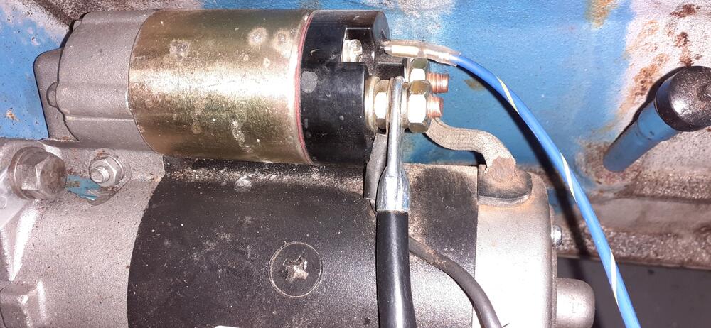
I'm not sure what lights you are referring to. When you place the key in start, the white/red wire going to the ignition switch connects to the green/white wire and the black/yellow wire. The green white wire goes to the tachometer and comes out black/white. The black/white wire goes to the coil positive. The black/yellow wire goes straight to the solenoid to engage the starter. There should be a spade connector on the solenoid to plug in the black/yellow wire. I can see the black/yellow wire going to the solenoid in you last photo, but the solenoid is partially obscured by the heater hose. Here is the solenoid power connection in my cars. In the first photo, the solenoid wire is the blue/yellow wire with the insulated connector. In the second photo, it is the yellow wire with the insulated connector and black insulating sheath. The smaller gauge red wires are for my headlight relays. I suggest setting up your voltmeter to verify you have voltage at the black/yellow wire when the key is in start.

-
I'll try to remember to set up a test rig to demonstrate testing this weekend.
-
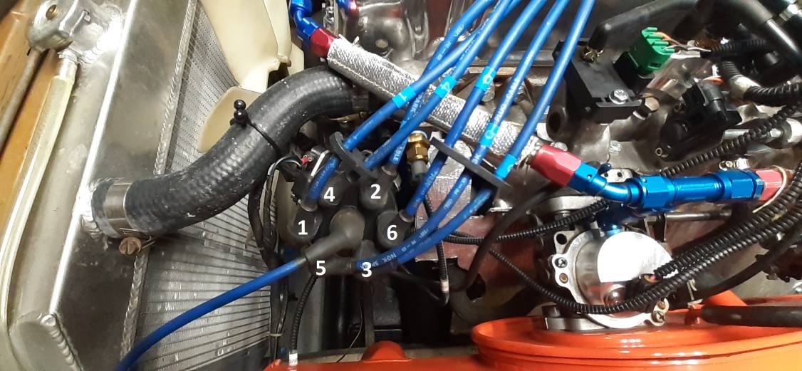
Missing data: What ignition do you have? Is it stock points? Pertronix? Crane? 1-2-3? ZX? Stock wiring: There is a black/white wire that goes to coil positive. There is another black/white wire that goes to the ballast, and a green/white wire that goes to the other side of the ballast. @Captain Obvious has a nice drawing that he labeled. If you need to figure out which wire is which, I did this video. However, you said you're getting spark, so in all likelihood that is wired correctly. You have not said anything about verifying static timing. You have not said anything about verifying firing order (1-5-3-6-2-4 counterclockwise) Have you verified that there is fuel in the float bowls? As @Zed Headsuggested, will it fire with starting fluid?

-
I'm not sure what to think without more information.
-
Post a video on Youtube of what is going on and link it here. Some visual evidence may help.
-
How old is the battery? Is the car running? If not, hook up a battery charger that has a 10A or 15A setting. Repeat and see if you get the same results.
-
The ZCON page for Birmingham is live now: http://zcon.org/conventions/2022/ Registration goes live on 1/1/22. Here's a link to the convention hotel: https://www.hyatt.com/en-US/hotel/alabama/hyatt-regency-birmingham-the-wynfrey-hotel/bhmhr
-
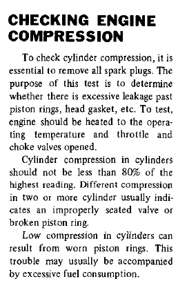
Why not go with what Nissan recommended to do for compression testing? (In this case, you can find it on page ET-5 of the 76 FSM)
-
What are you testing for? Are you looking for short circuits, or are you trying to find out how big of a fuse you can put in the circuit before it blows? Have you tried what I suggest in post #16?
-
An interesting aside, I was looking at various wiring diagrams for the Frontier, and I noticed that the wire from the battery is still white and the wire from the ignition in ON is still black/white (shown in a different diagram). Granted a lot of other wires have changed, but they have kept some of the basics the same for a long time. Note that there is a black rectangle by the S & L on the alternator in the drawing. That shows the orientation of the clip. Rotate that 180 degrees, and it looks like the one in the picture in my previous post.

-
That is correct, provided that ZCarDepot identified the terminals properly. From what I can tell, they did. https://trans-sen.en.made-in-china.com/product/VSGJimnPJKWj/China-Alternator-for-Nissan-Almera-X-Trail-2-2L-Mitsubishi-A3TB0771-.html

-
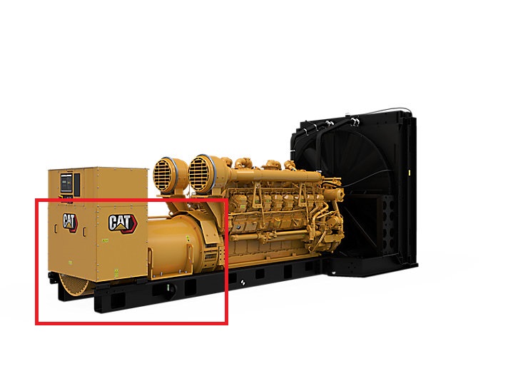
Stop and focus. I'm guessing that you're worried about making another mistake, and that's keeping you from reading carefully. From my previous post, "with the key in OFF, you should have an open line on the L or "lamp" wire on the T plug to the white wire, and it should have continuity when the key is ON. That is because it is a switched source." S - Sensing battery voltage. When the battery voltage drops, the voltage regulator excites the field to raise the output voltage of the alternator. L - Lamp: On a lot of old cars, there is a light to indicate a charging failure. Under normal conditions, the voltage is the same on both sides of the light. When the alternator starts to fail, the voltage drops on the alternator side, and the bulb lights up. When the car is off, the alternator is not producing any power (and therefore no voltage), so if you are not using a switched source, the charging light would be lit all of the time. By the way, these are the alternators I'm used to playing with. The alternator is inside the red rectangle. This one is a 16 cylinder engine with quad turbos. It will put out over 2 megawatts of power. The usual voltage output is 4.16kV to 14.4kV.
-
You know how to use the tool to give you the answer you seek. The S or "sense" terminal is to sense the battery voltage. Therefore, with the MSA jumper plug in place, you should see continuity between the sense wire at the T plug and the white wire where the fusible link plugs in. Just make sure that you Have the black (common) probe at the T plug. Have the ignition key in OFF. Conversely, with the key in OFF, you should have an open line on the L or "lamp" wire on the T plug to the white wire, and it should have continuity when the key is ON. That is because it is a switched source.
-
I looked for the Xenon air dams recently at Jegs. It doesn't look like they carry them anymore, at least for the Z car.
-
Who here plays with photo software? What are your favorite effects?


-
-
Start by giving us more background on the car. Who put in the new switches and why? Why do you think it has a headlight harness upgrade? The one sold by MSA/Dave Irwin has relays, but @Zs-ondabrain(aka Dave Irwin) had to modify the headlight connectors to make it work. Do you have a test light? Do you feel comfortable taking things apart? Are the parking lights working?