.JPG.cfcada9cf1c1b502df3f5f2f2ca3ff36.JPG)

SteveJ
Free Member
-
Joined
-
Last visited
Everything posted by SteveJ
-
 The red Z will be at Caffeine and Octane in Atlanta tomorrow. Even the wife is willing to get up early to see it.
 -
I'm not sure about the screw size/type, but I do suggest getting some JIS screwdrivers to reduce the chances of messing up the heads in future.
-
I'm in the NO RTV club. I worked on a guy's 280ZX turbo about a year ago. I was setting the valve lash for him. After that I was removing bits of RTV from the camshaft. Heaven knows how much got down into oil passages. Before putting on a new valve cover gasket, I thoroughly cleaned the mating surface on the head and valve cover gasket and sprayed out the valve cover to get more little bits of RTV out. Get a Nissan valve cover gasket. Line it up carefully. Don't over-torque the bolts when you put it on. Done.
-
Yep, I was thinking about our conversation about that when I saw jackmau's comment.
-
As long as it isn't from a 2+2
-
I did not find corresponding holes on the E88 head or N47 (Maxima) head on my cars. Sorry, I can't help you.
-
What holes are you referring to? A photo or two would help.
-
Nope. Tried that many years ago. I actually opened it up a little wider to the point where the gland nut would fit, but the crow's foot is much more sturdy. I wasn't confident that I got the surfaces flat enough for the gland nut after working on the fork cap wrench.
-
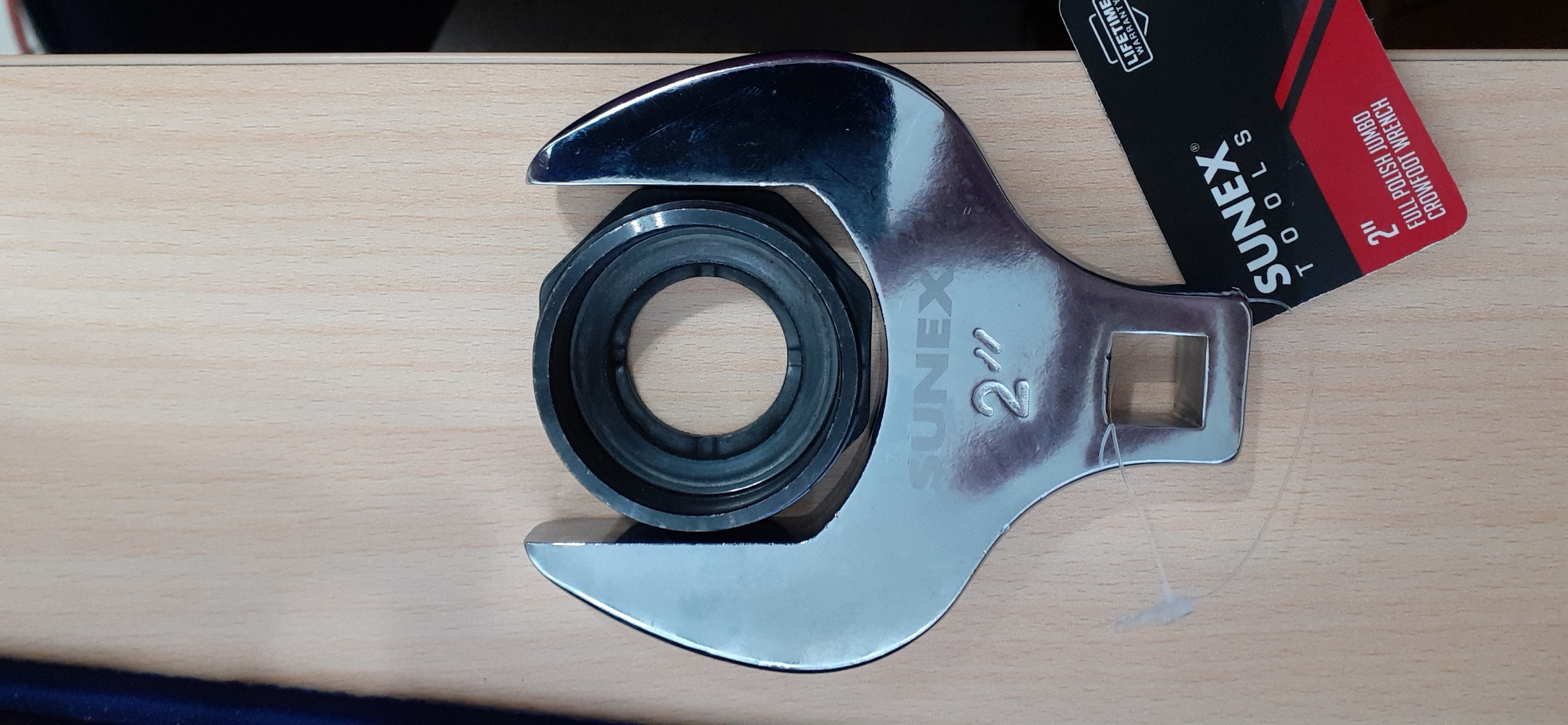
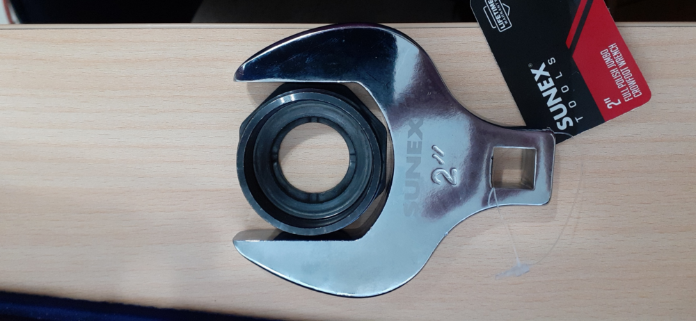
Some time this year, I want to replace the struts and springs on the 240Z. I have the struts, but I need to decide whether to use the Chevette springs I have on hand or go with the ZCarSource springs. Anyway, I have used the tongue & groove pliers (aka Channel Locks) on the 260Z gland nuts in the past, and I noticed that ZCarDepot came out with a gland nut wrench. However, me being me, I wanted to see what else I could find. I tried to find an octagonal socket, but no one seems to have a 2 inch octagonal socket. They are either much too large or much too small. Then I was doing some other tool searching and came across a 2" crow's foot. It was only about $20, so I pulled the trigger. The crow's foot looks like it could work. It certainly goes around the gland nut.
-
Don't ignore Bel-Metric. They actually have JIS sized M8 nuts and bolts.
-
Here's one place to start searching: https://www.transmissionpartsdistributors.com/nissan-infiniti-datsun-4/ You might reach out to ZCarSource, too. Holy crap, I think this may have what you need: https://www.transmissionpartsdistributors.com/fs5w71-fs5w71a-fs5w71c-fs5w71e-fs5w71g-fs5w71h/
-
For the internal shift forks, that's trickier.
-
https://www.thezstore.com/page/TZS/CTGY/classic22b01i
-
Even trickier. "I want to marry you, but she stays in my life, too."
-
To elaborate, the black/white wire should be on the anode side of the diode, and the white/black wire should be on the cathode side.
-
If I were to hazard a guess, I would say you have your diode backwards on the L terminal circuit. The other alternative is that there is a bad connection in the circuit.
-
It's not often a guy can keep his wife and girlfriend around so long. 😉
-
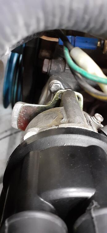
I just installed a Nissan Frontier alternator in the 260Z. I bought a new alternator from Rockauto. I did a video on it here.
-
Could someone have pulled the wrong part for you? They clearly show their other yoke is 24 spline. Just as an aside, I did a search on Summit Racing for 26 spline yokes. There are plenty of hits, but I don't know if any of them would work. The only yoke I have lying about is from when I tore up the u-joints on my driveshaft 6 years ago.
-
You're routing the black and red wires from the 123 over to the coil. You might as well route the blue one there, too, and ground it on the coil mounting bolt.
-
The lowest resistance ground is probably at the distributor mount. See my video linked below. You have the large gauge cable firmly attached to the starter. The starter is firmly attached to the bell housing that is firmly attached to the engine. Unless you have a large gauge cable firmly bolted to the chassis, the engine will have less resistance. I just went down to my garage to verify. From battery negative to the distributor mounting bolt, the meter read 00.0. From battery negative to the shock tower or bolt for the coil, the meter read 00.1. The 00.0 tells me resistance is probably less than 0.05 ohm. (I'm not sure at what point it might round up.) Either grounding place (engine or chassis) should work as long as the surface at all the grounding points is clean and not corroded.
-
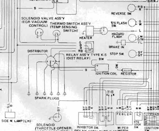
I misunderstood your question. The wiring diagram shows the black wire going to the negative of the coil. At the distributor, it meets up with the RB wire. (It could be RB from coil negative to the relay for all I know.) The coil positive should have the BW wire as I mentioned earlier. The RB wire goes to the relay that controls the advance for the dual point distributor and when the contact is closed, it goes to the black wire that goes to the other set of points. Pages EC-11 and EC-12 describe the system. When the car is cold, the temp sensing switch contacts are closed. The relay coil is energized, and the RB wire is connected to the black wire that goes to the advanced timing points. When the car warms up, the switch opens and the relay is de-energized. The contacts open at the relay, and the RB wire is open, leaving the retarded points in the ignition circuit. The 123 is not dual point to my knowledge, so you don't even have to worry about that wiring that I just explained. Without knowing which 123 model you're installing, I just grabbed one of the drawings. I can revise my explanation with more information. The BW wire goes to the coil as normal. No other stock wires go near the coil. (Jumper the GW and BW at the ballast as I mentioned before.) The black wire from the 123 goes to coil negative. The blue wire gets grounded. If the wire is short, you can ground it to the distributor mount.
-
A bad VR can drain the battery. That was one of my first Z car lessons over 28 years ago. For the inhibitor switch, look at the 73 wiring diagram for Automatic Transmission. Here's how the wiring works: The reverse switch AND the inhibitor switch are fed by a red wire. Each device is wired to a red/black wire that goes back to the reverse lights. I think this is a red herring (no pun intended). Anyway, the inhibitor switch should also have two black/yellow wires going to it. In other words, the inhibitor switch interrupts the solenoid power. No need to tie the 123 to anything but the black/white that goes to coil positive. There should be another wire from the 123 to coil negative to ground the negative when the distributor wants to fire. The stock wiring has a black wire that goes from coil negative to the points for the points to ground when it's time to fire. Then if there's yet another wire for ground, it could be grounded to the block for all you're concerned. Post the 123 wiring diagram to confirm. As for the green/white and other black/white at the ballast resistor, you can probably jumper those together.
-
Another Beverly Hills Car Club special...I'm not sure if someone else has posted it, but I just have the image of these twits searching through wrecking yards for cars to sell. https://www.hemmings.com/classifieds/dealer/datsun/240z/2454374.html

-
And another spammer just joined. https://www.classiczcars.com/profile/39043-ruhi-kapoor/