.JPG.cfcada9cf1c1b502df3f5f2f2ca3ff36.JPG)

SteveJ
Free Member
-
Joined
-
Last visited
Everything posted by SteveJ
-
 I am curious. How long have you owned this car? Have you seen any instances of a previous owner re-wiring or altering the wiring in the car?
 -
The plug I want you to find should be on the passenger side or maybe along the firewall. It will have the following wires: black/white, black, black/yellow and yellow (or yellow/black if the car was an automatic).
-
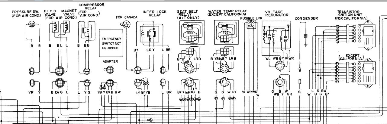
C-6 is under the dash. Of course, your ammeter is showing a discharge. You don't have the alternator hooked up properly, yet. The biggest problem you are having right now is that you aren't focusing on one problem. You are getting suggestions about two issues (alternator & headlights) in this one thread, and it appears as though you may be bouncing back between the two. Let's see if I can clarify the alternator issue for you. 1. You need wires from three locations going to a ZX alternator: Ground, battery, & ignition. 2. Your wiring harness was designed to utilize an external voltage regulator, therefore the harness requires some jumpers to re-route signals. 3. The white and yellow wires at that 6 pin harness should be jumpered together. That will give the new alternator the battery signal. 4. The white/black wire needs the ignition signal. Normally that would come from the wire at the #1 pin. According to the wiring diagram, that should be a green/red wire. 5. Since you don't have a green/red wire there, you need to get an ignition signal from somewhere else. The best alternative is probably the black/white wire coming off of the ignition switch. Trace that wire on the wiring diagram. One of the places it shows up in the engine bay is at the "Emergency Start Switch" that appears to have been deleted. If the harness was built to the wiring diagram, there should be a 4 pin connector in the engine bay on the passenger side with that wire. The thing that concerns me is that if you didn't have the green/red wire at the voltage regulator (or another wire in the #1 pin), I'm not sure how the charging system was working to begin with.
-
The three wire connector is for the AC. Have you tried to see if the green/red wire is on the C-6 connector? One of the issues is that the wiring diagrams show a seatbelt interlock relay system. I don't know when Nissan ditched it. You can find many threads about defeating them in the 74. The manual I downloaded from Xenons30 has too many artifacts to be truly useful. On the 240Z, the black/white wire from the ignition was joined with the white/black wire. Wiring that way may get the alternator working. Then you could focus attention on the lack of headlights.
-
Okay, so let's get this straight. The wiring diagram of the 75 identifies the wire from the engine bay harness going to the 1 pin on the voltage regulator connector as green/red. You say that wire was not present. I see a blue wire in the picture. Does it get 12 VDC when you put the key into the Run/On position? Does it lose 12 VDC when the key is off? Was the blue wire next to the green wire on the 6-wire connector? If so, that's the same as green/red. That would go to the white/black wire.
-
Okay, now I have more to go off of when I look at it later. That is if BeermanPete doesn't beat me to it.
-
What wires did you end up connecting to each other? Are any wires loose? Without that information, you will only receive guesses.
-
I noticed that, too.
-
I think my wife would have my hide if I paid more for a model of a Z than I paid for my actual Z cars.
-
I this this speedo cable might work for you: Datsun Bluebird 510 620 1200 1400 1600 240Z 260z 280z Speedometer Cable New | eBay.
-
I haven't been to Matt's shop, but I have seen his trailer and some of his cars. I guess I'll have to get myself invited over sometime.
-
Also, you can always find a fresh discount code here: http://www.retailmenot.com/view/rockauto.com
-
With that much rust, don't expect too much. $1500 running.
-
The colors of the wires on the choke switch do not matter. It's the colors of the wires from the body harness that matter. Keep in mind that the connector for the map light should also be red/blue and black. By the way, you can get some, if not all, of the connectors at OEM-Type Bullet & Spade Electrical Connectors for 1960's through 1970's Japanese Vehicles... Bridgestone, Datsun, Hodaka, Honda, Kawasaki, Landcruiser, Suzuki, Tohatsu, VW, & Yamaha. Which side is coming from the dash harness? I'm guessing it's the right side since it has red/black and black wires. I don't know at this time what the blue wire is, though it is some accessory function. If the wires both come from the dash harness, they won't connect together. Clean up the wires better and describe the colors. Edit: Look at BE-4 in the 1973 FSM. A couple of the connectors in the 72 manual on the corresponding page were lacking color descriptions. Those colors are listed in the 73 FSM, at least in my copy.
-
If I can remember to track it down, I'll look for my spare switch and take pictures for you, so you can see what you're missing.
-
Thanks for joining, Ed. I'm interested in hearing more, too.
-
That's easy to understand. It took me a while to realize that there were several different switches for the headlights.
-
Actually, according to the FSM, the standard 72 combo switch does switch the positive side on the headlight. The White/Red and Red wires going to the headlight side of the switch are positive. Also, the parts manual shows a change in part number starting in September 71. Now from what I understand, it wouldn't be unusual for Nissan to have put 1971 wiring harnesses and switches into 1972 models to use up stock. Do you have an early 72?
-
I can't tell if they are series or parallel. I looked more carefully at SuperBrightLEDs' website. They say whether or not their bulbs are polarized. Also consider that for applications like our cars, there won't be too much stress on the bulbs. After all, how often do you drive at night? By the way, with Amazon Prime, you can get them for $2 per bulb when you buy at least $25 worth of Amazon Prime merchandise. Edit: My bad. It's the white LEDs available for $2 per bulb.
-
I just bought some 5 LED bulbs through Amazon (Cutequeen LED Car Lights Bulb Green BA9 BA9s 5050 5-SMD BA9S, 53, 57, 182, 257, 1895, 6253, 64111, 64113 (pack of 2) : Amazon.com : Automotive). I had to remove the green filters in the gauges, but the light output is great. I'm going to buy some more to put in the speedometers and tachometers of my cars. There is one caveat, though. The polarity is reversed on these bulbs, so I had to reverse the positive and negative. IIRC some of the sockets ground on the gauge, so these bulbs would not be appropriate for those gauges.
-
One point of clarification: That description applies to 72 through 78 Z cars. The 70 and 71 are a little different. The headlight switch in those is not on the positive side of the circuit. It completes the ground between the high/low beam switch and chassis. There is no switch on the positive side of the circuit in those cars.
-
You aren't following it back to the high/low beam switch. That switch will connect either the RB or RW wire to ground. I have three comments on that diagram. 1. I would reverse the 30 and 87 pins. Bring the 12 VDC from the battery to the 87 pin. Most relays you find today are SPDT. That means there is a normally closed contact designated as 87a. When the coil is de-energized, 30 and 87a are connected. If the 87a comes into contact with ground, you'll blow the fuse. If you bring in 12 VDC to the 87 pin, it is just an open circuit when the coil is de-energized. 2. If you use this design, I would suggest a 12AWG wire for the wires going to the 87 and 30 pins. Match up the 12 AWG wire with a 20A fuse. 3. This is the way to wire it if you are considering LED headlights. Otherwise, it may be easier to go with Dave Irwin's design that you can purchase from MSA.
-
See, he beat me to it.
-
You have to get the switch knob off, and then you can loosen the ring that holds it on. Be careful. There are parts you can lose. Disconnecting isn't too bad. The challenging part IIRC is getting the optical fiber back in place for the light.
-
Excellent information. We can work with this. I'll take a look at the wiring diagrams and see if I can give you some more to look for. That is unless BeerManPete doesn't beat me to it.