


z3beemer
Free Member
-
Joined
-
Last visited
Everything posted by z3beemer
-
Is there anyone who has a speedometer from a 240Z and can send me a picture of the back of the speedo. My latest issue on my 73 restoration is that the brake light warning light stays on all the time when the lights are on (only when the lights are on). I'm thinking that on reassembly I may have mixed up the instrument bulb with the warning light bulb. The warning light stays lit when the lights are on even if I disconnect both the emergency brake switch and the brake master cylinder warning switch. Since I can't see the back of the speedo, any switching I would have to do I'd have to do it by feel A picture would help greatly.. Thanks!
-
-
Have not checked the coil but it's cheap enough to just replace it to eliminate the possibility.
-
Mark it seem to be ok when driving it initially and at low rpm but started breaking up as I increased speed and rpms. It's ok at high rpms when idling with no load. This was the first shakedown ride so I need to do some more investigating. I think the next thing I'll try is leaning out the front carb a little. If that doesn't help maybe recheck float adjustments again.
-
I guess a mechanical issue with the 72 distributor is a possibility but points, cap rotor and condenser are all new (not that that's a guarantee they are good). Points were set using a dwell meter , not a feeler gauge. Other things that have me leaning toward fuel issue is that it only happens under load. At idle I can run the rpm's up to several thousand rpms with no issue. Also, if it was ignition related it would be odd that it only affected cylinders 1-3 and not 4-6. Another fact that may be contributing to the problem (but not sure it would), currently, I do not have the entire exhaust system installed, only the headers are installed. Planned on taking it down to the exhaust shop to get it finished out once I got it running decent. I still have the 73 distributor if I want to swap it out, I was unaware until this post that you could run a dual point distributor and use it as a single point set up. Thanks for the input. I appreciate it.
-
Captain Obvious, your summary of my wiring is correct. I was pretty sure my logic on how I connected it was correct, just wanted a second opinion. Thanks. I don't really think my current issue is ignition related. I think it is more fuel related. Maybe more carb tweaking. I checked the plugs and 1-3 appear to be running rich, 3-6 appear to be more in the normal range. Next I'll try leaning out the front carb and then rebalance. Other possibility may be float adjustment but I think I was pretty accurate when I adjusted them. I'll try the easy stuff first.
-
I've searched the forum on this topic but could not find exactly what I'm looking for. Here's the issue: 73 restoration. Originally an auto trans with dual points. I've converted to manual trans but I'm utilizing the original wiring harness. All the pollution equipment has been removed. The intake, carburetors, distributor, trans/clutch parts from a 72 have been installed. Since the 72 dist. has only one points wire connection and the 73 had two, I've connected the two wires from the 73 wire harness together and connected them to the single connector on the 72 points. Would this cause a problem? The car starts ok and runs ok but is currently breaks up after a few minutes driving and higher rpms. Before I start more extensive troubleshooting to correct the issue, I want to eliminate the easy stuff first. So, the questions are: connecting the two point wires from the dual system together and connecting them as one to the single contact point on the 72 distributor OK to do? If not, which wire from the dual point harness should be connected to the distributor and which one should be disconnected? Your input is greatly appreciated.
-
Not sure what refrigerant you have in your car R12 or 134A but if you're swapping out the compressor it is most likely is set up for 134A. If the old system was R12 you need to flush the entire system and replace the oil using a polyoester synthetic oil. R12 systems used a mineral based oil and since in a refrigeration system the oil travels in the refrigerant you need to flush it before converting to 134A. Otherwise the mineral based oil will turn to sludge. If you decide to stay with an R12 system expect to pay big bucks for R12 (if you can find it). I'm talking $60+ per pound. I used Auto AC Solutions out of Texas for my 73 restoration which formerly had an ARA system. Nice guy, really helpful. If you decide to go that route and would like more info on my install, contact me and we can talk about it (good & bad). I have a post on here with some of the details of my install. I believe it is under the Heating / AC category.
-
Success! I made all the changes we talked about, bled the system (again) and now have good pedal feel and brakes. I'm pretty sure, as you all suggested, the caliper issue was the key problem. Thanks for all your help....You Guys Rock!
-
Thanks guys for all the clues. A few follow up questions/findings: Yarb: I like your adjustment method. To clarify: I would put the lithium grease inside the hollowed-out section of the MC piston as far forward as possible. Adjust pushrod until it just touches the grease. Would I then turn the adjustment 1/4 turn. Do I turn it in or out? Terrapin Z: I did not follow the exact method for adjusting the rear brakes. Did it the old way adjusted them up until they locked up, then backed them off until there was a slight drag on them. Your suggestion makes a lot of sense. Regarding lack of pressure. I will readjust. Zed Head: Just went out to the shop to check the location of the bleeder plugs on the front calipers. They are at the bottom. Your info and rechecking the FSM, they should be on top. I'll correct that. Your description on pedal action is quite similar to the problem I am having. FYI: In addition to having the symptoms Zed Head described regarding pedal action, when the pedal it pushed as far as it will go, there is some braking action but neither the front or the rear brakes will lock up. I'll make the changes and let you know how it goes. Thanks again.
-
Yea, that's the same pic I have, but like I said even with the end screwed all the way in it still sticks out mor than 4 mm. Do you think my logic makes sense that more extension on the pushrod would help my problem?. I just get the feeling the master cylinder piston is not being pushed far enough forward to lock up the wheels.
-
So, I'm nearing completion on my 73 restoration and I'm having problems with the brakes. They just don't feel right and when applied will not lock up the wheels. I'm not running the engine but they hydraulic action should work with or without the booster having vacuum on it, otherwise you wouldn't be able to stop the car if the master vac failed. I've been working on brakes for more than 50 years and have never seen a system where the brakes would fail if the power booster failed. There's not that many components in this brake circuit so I can't believe I'm having this many problems. Searched the forum and though I may have found the issue being the reaction disc. So here's what I've done so far: all new brake lines, new master cylinder, rebuilt proportion valve, rebuilt brake light switch, adjusted pedal height, bled entire system numerous times. No leaks anywhere and flow out the bleeder plugs on each wheel. The proportion valve is on the fire wall not at the rear brakes. Retested master cylinder to be sure it was not defective. It is not. Disassembled the master vac to check the reaction disc. It was in the proper position. Cleaned it up and glued it on just to avoid future problems. While I had it apart, I freed up the threaded end of the push rod using the thermal wrench (that was a real nail biter}. I'm kind of leaning towards insufficient travel of the master cylinder piston. Looking at the pic posted by Zed Head I need to know what dimension "B" is. I'm not sure which FSM the pic came from, but I checked 71-72 & 73 FSMs and cannot find that pic or the dimension. My 73 fsm says 3.5-4.0 mm from flange surface (which I assume is the front surface of the spaces that goes between the master vac and master cylinder) to the end of the pushrod. Well even with the pushrod end screwed all the way in, it sticks out more than 4mm, more like 8-10mm. So if anyone knows what the "B" dimension should be, let me know. I'm thinking with the problem I'm having, more stick out of the pushrod would be better. I'm considering backing the pushrod all the way out until it touches the master cylinder piston, then turning it in an 1/8" or so. Any thoughts suggestions or other things I should be checking?????
-
View Advert Fan Shroud 260Z Fan shroud from 260Z w/ stock radiator. Two-piece plastic, good conditions (no cracks). May work on other models or radiators but check before purchasing. Buyer pays shipping. Not heavy but will require a large box (probably around $20). Advertiser z3beemer Date 07/25/2023 Price $40 Category Parts for Sale
-
The closer I get to completion on my 73 total restorations the more nuisance problem I encounter. This time it's brakes. Spent the last few hours reviewing related post and picked up a few tips but not my exact problem. I Replaced all hard lines and hoses, reused the master cylinder, proportioning valve, master vac, and brake warning switch. Assembled everything and blead the brakes. I had flow at each wheel bleeder. However, after bleeding I pumped the brakes a few times and they became hydraulicly locked (solid pedal). I figured the return port on the MC may have become plugged. Rather than fool around with it, I just ordered a new one. Problem solved. Rebled the system, flow at all wheels. But pedal doesn't feel right and the brake warning light is illuminated. So back to the drawing board. Before I tear into the proportion valve and warning switch, I want to do the easy things first. Adjust pedal rods, and rebleed the whole system. Currently pedal height is about 7-3/4 , I know its supposed to be 8.11" . May need to go a little more since there is no carpet is in the car yet. I also want to check the length of the of the push rod that goes between the master vac and the master cylinder. According to the FSM this rod should be adjusted so the end protrudes 3.5-4mm (.130-.150")from the front flange on the master vac to the end of the push rod. This seems very small to me. Does this seem correct? After I make these few changes if it still feels incorrect, I guess I'll have to tear into the warning switch and proportion valve (which will be a real PIA). Any help greatly appreciated...Thanks
-
I'm trying to find the proper orientation of the marker lights on 73 Z. As you know they are thicker on one end and thinner on the other. I've look at numerous phots of z's and it seems to vary. Anyone know the correct orientation? Does the wider part go towards the front of the car of the back or the back? Are the front ones orientated differently than the rear? Thanks for your help. Didn't find an answer in the other postings,
-
By the way those filter screens are readily available. I think I got mine online for like $1 a piece.
-
After you remove the screw from the slide that holds the needle you can grab the needle up high right near the bottom of the slide with a pair of vise grips and twist it while applying downward pressure. Don't worry if you get some marking on the needle from the vise grip. That part of the needle never gets into the nozzle (jet). I would still soak it some sort of penetrating oil before attempting the removal. Acetone and automatic transmission fluid is cheap and works well. Use a 50/50 mix.
-
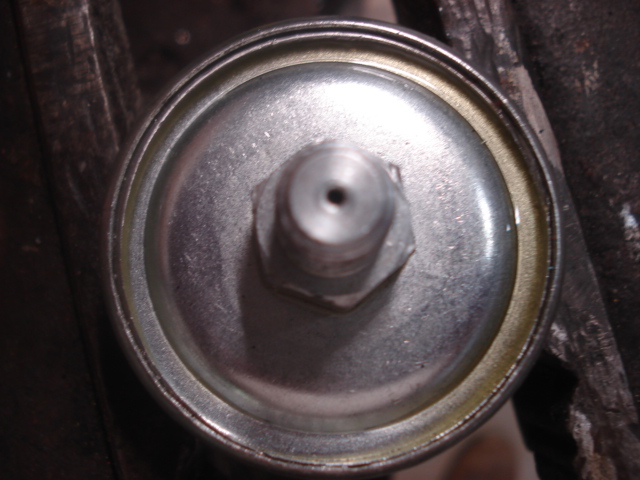
On one the first starts on my 73 restoration project, I notice I didn't have any oil pressure showing on the gauge. I was pretty sure I had oil pressure because the engine wasn't making a lot of noise but shut it down just to be on the safe side. Using the forum, I was able to find out how to check to determine whether it was the gauge or the sending unit. Turns out it was the sending unit. I ordered a new one from Zcar Depot. I installed it and that took care of the issue. I started noticing a small oil leak under the car. I had a hard time locating the source but finally discovered it was coming from the oil pressure sending unit. It appeared dry around threads, but i removed it and sealed around the threads with permatex and reinstalled, still leaked, still dry around the threads, tried again using teflon tape, seemed to get worse but still dry around the threads. So i removed it again and figured it may be leaking around the back seam where the front and back portions of the unit come together. I did notice some oil there. On the bench, I injected some air into the unit and quite a bit of oil came out around the seam. I notified the guys at Zcar Depot and they were very accommodating (as usual) and sent me out a replacement. The first one they sent me was silver and screwed into the block very easily. I was able to get 3 or 4 turns on it before having to use a wrench. The second one was a Beck/Arnley brand and gold in color. I had a hard time getting it started in to the block and when I did I could only get about 1/2 turn on it and it was very tight. Here's what I did. The threads appeared to be 1/8"-27 NPT thread. I ran a tap in the hole in the block. It threaded in smoothly without the use of any tools. Then I ran a die of the same size on the threaded side of the sending unit. It took a little more effort but nothing excessive. I then buffed the threads on a wire wheel to remove any of the gold plated coating. I was now able to start it into the block hole about one turn or so. Using a wrench I would turn it one turn at a time then back it out, it was still pretty snug but seemed to be going in smooth and straight. I did this 4 or 5 times, turning it in a little deeper each time until it felt like it bottomed out (or was in as far as it would go). That took care of the problem andi the leak. I thought this info may be helpful in case others run into the same issues. The attached pic shows where the oil was leaking out once I applied air pressure to it.
-
So, I search the forum for an answer, got some info, but not exactly what I need, so here it goes: I'm doing a 73z completer restoration that was originally an automatic and I've converted it to manual using 72z doner parts. I initially left the car with points while starting it and checking it out. It runs with points. Now I want to make the Pertronix conversion (with the flame thrower coil). Since the car was originally an auto it had dual point distributor with one wire to each set of points. I replaced the 73 distributor with a single point distributor from a 72 Z. Since I'm using the original wire harness from the 73, it had two wires the connected to the points. Since I wasn't exactly sure which wire to use, I ran the two wires together then connected a single wire to the points. All ran well. The kickdown switch has also been removed. (I understand that is what sends power to the second set of points). So here are my intentions and questions. I plan to disconnect the ballast resistor and connect the 2 wires together. I plan to use the existing 73 wire harness. First question: There are two condensers in the circuit; one on the side of the distributor that connects to the points, the other is mounted near the coil and connects to the + terminal on the coil. Can both of these be removed when using the Pertronix system? Second question; the two wires on the Pertronix module are red and black. Should I connect the red wire to the wires that previously connected directly to the points (these would be the two wires on the harness that I tied together to make a signal connection) and the black wire from the module to the -(neg)on the coil or is there some other way I should connect them? Thanks in advance for your help. Paul (z3beemer)
-
Yea your probably right. Not sure I'll find a metal one anyway. If not, I'll get the fiberglass one from Motorsport. Talked with them today and they are currently out of stock but are expecting them back in first week of June. Maybe something will show up between now and then.
-
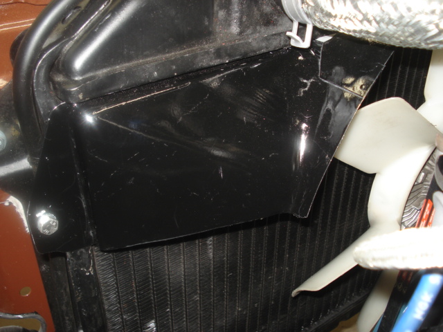
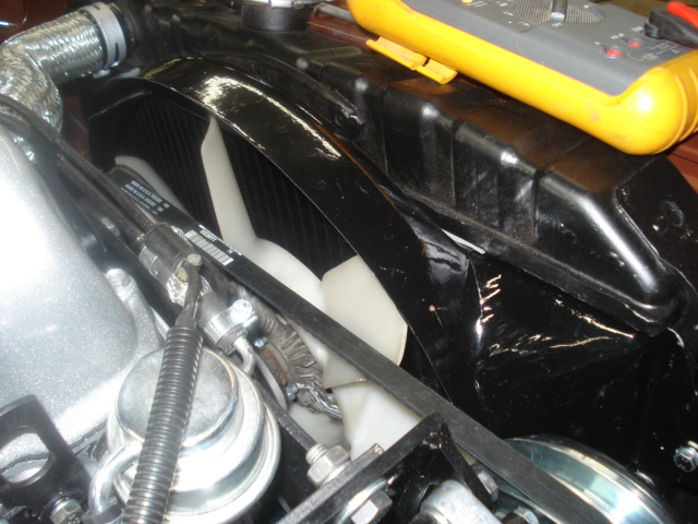
Well, based on the input of the knowledgeable members of this form, it seems the original shroud on the 73 Z was a one piece metal shroud. The one on my car appears that it was one piece at sometime and someone cut it to ease installation and removal. Unfortunately, when I got the car only the top portion was attached. So I guess I'm looking for a complete metal fan shroud for a 73 Z and I'll cut it accordingly. Otherwise, I guess I can get the fiberglass one from Motorsport and cut it in half to ease installation. So, if anyone has a metal one for a 73 let me know.
-
Here are a few pics
-
Trying to post a few pics but for some reason I keep getting an unknown server error. Don't know why. I'll try again later.
-
When I got the car it had only the top half of the metal shroud and it fits the radiator fine. 73 240Z. I recently purchased a two piece plastic one from a 260 but it doesn't even come close to fitting.
-
Looking for the lower half of the stock metal fan shroud used on 73 240z. I really only need the lower portion but if someone has the whole shroud to sell I'd be willing to buy the complete shroud (depending on price)

