mdbrandy
Free Member
-
Joined
-
Last visited
Everything posted by mdbrandy
-
 Another thing I am not particularly familiar with. The only graphics package I have right now is JASC Paintshop Pro, and I was just trying to see if it had a raster to vector converter and I don't think so. Never had to do it before. I can save from Paintshop to .psd, .gif, .jpeg or whatever. Don't know what R10 is - is it a package or a format? Do you have a favorite shareware converter?
 -
Yup, especially if I use unstructured grids, they aren't too hard to change. The hardest part is getting the base description right.
-
IGES is a text-file generic CAD description specification that most CAD packages can save files in. HOWEVER, it is buggy, and iges files saved by one package may or may not work well in another. I've found that PRO/E can read iges files from most other packages, and then if I resave them from PRO/E, then Gridgen can read them. We also have Patran which can make, read, and save iges files, but not as well as PRO/Engineer. Anyway, don't put yourself out too much. If you like doing stuff like this, go for it! I'd love to have the CAD description... Thanks.
-
May73GNZ is right - if you click on them they get quite large and detailed. If you want to do it, that's great - I was just wondering if anyone already had. I know I've seen people making illustrations of various Z's, but that's probably in paint-type packages and not CAD. Since I need surface descriptions, pixel images aren't useful. Have you ever saved anything in iges format before? We use Pro/E here, although I don't know much about it. Our CAD modeler then saves in iges so I can read the model into a program called Gridgen. It doesn't understand native CAD formats unless you pay more money :tapemouth .
-
Hmm. Still can't be displayed. Acts like it is loading, but then dies. Maybe your post has a lot of people looking at it now . Although there were only 24 views on this thread when I looked before, so you wouldn't think that would tax any server... If anyone is interested in the kind of things I'm talking about, our website is www.csar.uiuc.edu. Kind of out of date right now, but still has some interesting stuff.
-
I've got many/most of those drawings, but that still makes me do the CAD myself, which I am not skilled at. Once I have a CAD representation, I can mesh it in a variety of ways. I tried the Aero URL but it can't be displayed for some reason. Sounds interesting, though . What I'd like to play with doing would be essentially calculating the entire flow field around the car. Might be interesting to see what kind of turbulence is predicted behind it with our codes. We're always looking to find new simulations to do. We normally do solid propellant rockets, but we've done airplane wings, shock tubes, and even flow in an artery. I'd essentially set it up like a virtual wind tunnel and flow 70 mph air over it to see what happens. Expensive computer toys .
-
Looking for essentially a surface shell drawing of an S30 chassis. All the talk of drag coefficients and such in one of the other current threads has made me want to see what would happen if I tried modeling one of our cars in one of the CFD (computational fluid dynamics) codes that I run every day. Might be fun in my "spare time" . Would need to be either a format that Pro/Engineer can read, or a generic IGES file exported from your CAD system that I can read into our finite element mesh generation code. Even a 2D elevation outline might be interesting. Our codes are 3D, but I can mock up a 2D slice around the car. I'm just not very good with CAD. Got other people to do that for me! Anyway, just a thought :classic: .
-
Just to see if anyone else has seen the same thing... The rear axle - the part that goes through the hub through the rear bearings and has the wheel studs through it's outer plate. Has anyone looked closely at the BACK of the plate that the wheel studs goes through? On mine there is a thin plate that the wheel studs goes through first (looks like galvanized steel), but I'm looking at the back of the actual heavy steel plate that the wheel studs go through. I'd swear that it's plated! It almost looks like chrome. The front of that plate, where the wheel studs come through was nice and rusty as expected. The back, where you insert the wheel studs, was nice and clean (except for a few little corrosion blooms), and very shiny! Strange. I wire brushed the few corrosion spots and those areas are now, of course, nice and dull. Might have been a mistake. So, anyone else noticed this? These axles are from a '78 280Z. Just wondering...
-
Within a week or two, I'll be doing this same job (putting back together after painting this weekend). So I've been thinking about it. The inner wheel bearing is easy to tell if it is seated or not, since you install it before you put the axle in. You can look at it from the wheel side, and see if it is up against the inner flange. No worries. But I have been wondering about the outer bearing. Even if it is seated perfectly on the shaft, you then have to force the outer edge of the race into the interference fit inside the hub. And there isn't any way to see if it is completely seated. I really don't think that the torque on the shaft nut will pull it into place - like the other bearing races, I'd bet it has to be "pounded" into place with an appropriate drift or bearing installer. Or in this case, I guess you'd have to pound on the outside of the axle plate to seat that outer bearing. If the outer bearing isn't seated completely into the hub, as you tighten the nut, the inner bearing race (of the outer bearing) would be pulled inward toward the distance piece (it won't be against the distance piece, since we're assuming it isn't completely seated in the hub), and would then bind the outer bearings. That's what I expect is happening to you (just an educated guess). So, how did you install the outer bearing/axle into the hub? Were you depending on the shaft nut to pull the outer bearing into place? I don't know that that won't work, but I doubt it. Any more experienced opinions?
-
How big a compressor do you have? My little Harbor Freight cabinet taxes my Craftsman compressor. It is only rated at about 6.8 cfm at 90 psi. When I start blasting it runs continuously, so I can only blast for "a while" and then let it rest. I'd love to have more professional equipment, but it isn't in the budget right now.
-
I shall look this evening...
-
I think I still have the headers that I cut off my '70 240Z. If you haven't found anything else, I'll look tonight. I'm taking the car back to stock, and the headers were rusty junk anyway, so if you want the flange, I can cut it off. I wouldn't need any $$ for it, but I'd need you to pay for shipping. Let me know if you're interested and I'll look.
-
The taller strut mount insulators on your 2+2 struts look like the ones I have on my bench off my '78 280Z. Much taller than the 240Z one you have in front.
-
I did almost exactly what you've done on your suspension. Front end is done and back in the car, and the rear is in a million pieces, and about half of it is repainted. I was just out in the garage cleaning the old grease out of one of the rear stub axles. I hope to have everything painted by the end of this weekend, and then next weekend put it back together! I also used Eastwood's rust encapsulator and chasis black. Did you get their "new" chassis black, or the original? The new stuff says it is tougher and easier to recoat, but I had two cans of the original so I used it. I don't know how many hours I spent in front of wire wheels and with my little harbor freight sandblaster. I found that sandblasting is really slow, but the only way to get to some of the areas. I probably got rid of 98% of the old paint and rust, but I used the rust encapsulator because of that other 2%. 8" wire wheel in the bench grinder and a twisted wire cup brush on the hand grinder took care of a lot of the paint and rust. Looks awesome! Wish my frame and engine bay looked as good as yours!
-
What makes it so hard to get back together (he says...anticipating having to do it soon...)? It looks like you should just be able to slide the shaft in a little bit, add a layer of balls, in a little more, add a layer of spacers, in a little more....etc. until you get them all in. Is it a matter of keeping the shaft straight in the yoke bore or something? I just took some pics of the pre-cleaned up parts. As I clean everything up and then get ready to put it back together I'll take more and post some. Edit: Oh, and I am rebuilding the rear on my 1978 280Z, so I am working on a 280. The 240Z rebuild is coming along a lot slower since I'm trying to get the weld work done before tearing into too much of the mechanicals.
-
I "think" I'm OK. I just wiped down all the small parts and did a quick inspection, and all the balls look OK. A couple of the plastic spacers are a bit rough,but it looks like they probably came that way. The concave ends where the spacers cup each ball look fine. If I come across anything as I look closer, I'll let you know. Thanks for the offer!
-
Will do. I photo document just about everything I'm doing. That way I can remember how to put it all back together! Also, when I do essentially the same thing to the parts from the '70 240Z, I will at least have a fighting chance of it all going smoothly! I'll let you know if I have any trouble with the boots . The new boots I put on the steering rack were a major pain to get on, but they stretched quite a bit...it at least looks like sliding them onto the shaft here shouldn't be as hard as the steering rack...
-
The grease in mine looks like it started out as the kind of translucent yellow grease that Nissan seems to have preferred. Up in the grooves, it was pretty black, though. The stuff at the bottom of the yoke behind the shaft was still fairly clear and yellowish. There was still a lot of grease in there, and it probably didn't actually need to be redone, but now I'll have new, synthetic grease in the sliding portion, new U-joints, new boots, and a nice paint-job on the outside. Hopefully I won't have to touch the half-shafts for a LONG time!
-
There IS a sleeve yoke plug, but not a snap ring to go with it on the 280Z half shaft. Interestingly, I just went out and looked at the half-shafts from my 240Z, and they DO have a snap ring at the plug end, and the plug is apparently flat-faced toward the diff. On the 280 shafts, the plugs are dome-shaped with a lip that apparently compresses as they are driven in, obviating the need for the circlip. Anyway, as noted in my last post, as jmortensen and bambi had told me, after removing the main circlip, you just pull the shafts out. However hard you might have to work to do that!
-
Ok, got 'em. I initially gave up on the first one and moved on to the 2nd to make sure it would give me the same trouble. Well, it didn't. Just as directed, I slid the boot back took off the big circlip and washer, and pulled the shaft out. It wasn't easy, but neither was it a big problem. Came out balls, spacers, and all. So, back to the first one. Still wouldn't budge by hand (yoke in vice, pulling up on shaft by hand, wiggling, rocking, etc. So I remembered what jmortensen had said "kind of a slide hammer effect". I then put my jack handle through the U-joint yoke holes on the shaft end, locked the yoke end in the vice, and used a 9 lb slide hammer to yank the sucker out. Now, it STILL took me probably 15 pulls on the hammer, with the shaft inching out little by little all the way until the last ball was exposed (I removed balls and spacers as they showed up). Then finally, the last pull got it out. Now all I have to do is examine it all for damage and try to figure out why it was so locked up to begin with. Thanks for the advice all. Mark
-
OK. Just making sure I didn't have the wrong things off. I've already taken out the first row of spacers. I'll try to finagle things out one row at a time instead of brute-forcing it and see what happens. Thanks for indulging me here! :laugh:
-
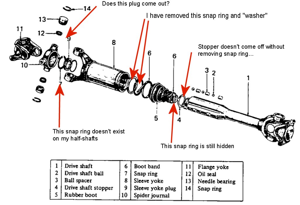
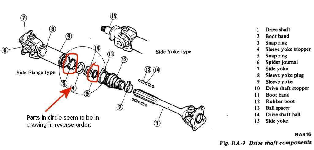
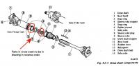
Well, I guess I'm weak or something. No joy. The weird thing is that there is a very audible clunk when I pull the shaft out, like there is still something attached that shouldn't be. So, I have attached two drawings for your "amusement". The first is from my '70 240Z factory manual, since I think it's a better drawing. Note the circlip and stopper on the end of the shaft that I have not removed, versus the circlip and washer that I have removed. Have I removed the correct thing? The 280Z drawing (note that I am working on 280Z shafts) shows similar parts, although the circlip outside the yoke plug is not there in the drawing or on my shafts. The haynes manual and the 240Z factory manual say to remove the plug snap ring and the plug, and then remove the circlip and stopper from the shaft. The 280Z factory manual doesn't mention removing the plug, and it is not obvious how to do so (I guess I said that before...). Which circlip did you guys remove?

-
Ok, so the consensus is PULL HARDER! I shall retire to the basement and do so.
-
OK, so I'm deep into the rear end rebuild right now, and I'm trying to take the half-shafts apart to give them their "30,000 mile repack" that no one ever actually does. I already have all the U-joints out and I'm replacing those, and I've bought new half-shaft boots (They're actually still available from Nissan, and not very expensive). To use the boots, I have to take the shafts apart anyway, so a good cleanout and regrease would be good too. But. I can't get them apart. I have the boot slid back, I have the circlip and "yoke stopper" removed (essentially a big washer). I can now slide the shaft out far enough that I can get the first layer of plastic cylinders out (I can see the first layer of metal balls after that), but then the shaft stops and won't move further. The factory manual just says to remove the circlip and stopper, and then to draw the shaft out. But it appears as though there is a 2nd circlip on the end of the shaft, but I have no idea how to get to it. There is a plug in the end of the yoke, but no obvious way to remove it to get to the circlip. Has anyone actually ever disassembled and regreased their halfshafts? What am I missing here? I thought about hammering the shaft back toward the plug to try to knock the plug out, but the manuals don't say anything about this, and I don't want to hammer on things I don't understand... Thanks.
-
If I'm understanding what you have, the "rubber washer" is a spacer for the rear struts only. On the front struts, there is a bearing that fits in this place you seem to have indicated. And these parts are not where the rubber boot would attach. On the strut, you have the spring, the upper spring seat, the bearing (or rubber spacer), and then the big rubber top mount with the three studs. The boot fits around an inner lip on the upper spring seat. Hope that's clear...