


240260280
Free Member
-
Joined
-
Last visited
Everything posted by 240260280
-
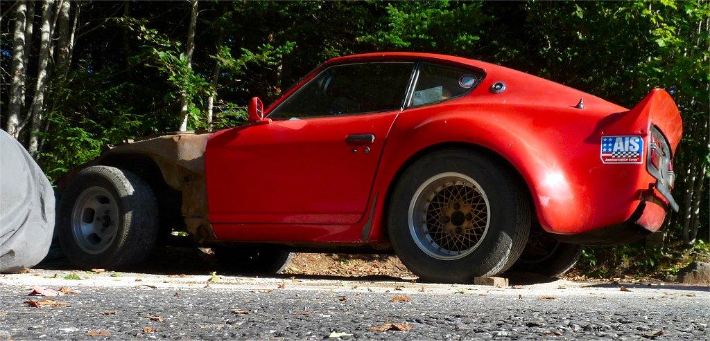
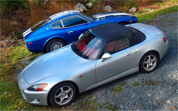
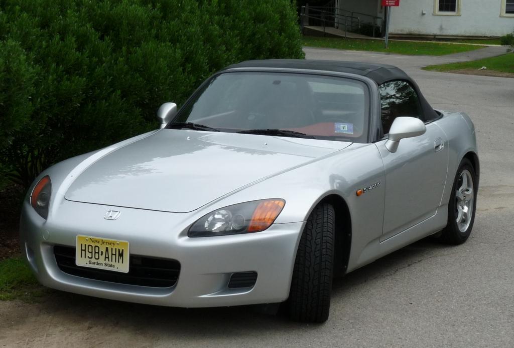
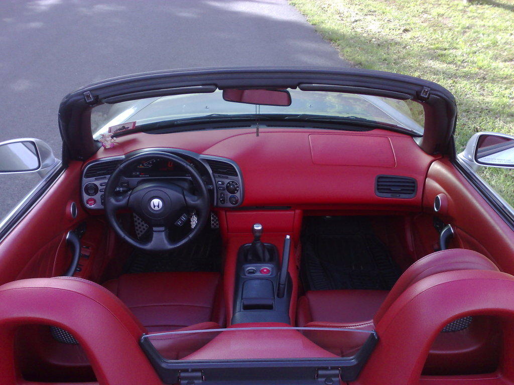
 Car is in Nova Scotia. I have two and need to get rid of one. The car was originally from NJ so import back to USA should not be tough. 107,000mi $12,000 USD

-
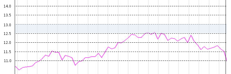
Great. That is appreciated, If you use the same flat area and punch the throttle at the same cruise speed for all runs that would help reduce any variables. If you still peak at 12.5 on your new runs then a run on the 160 main jet would be nice to have too.
-
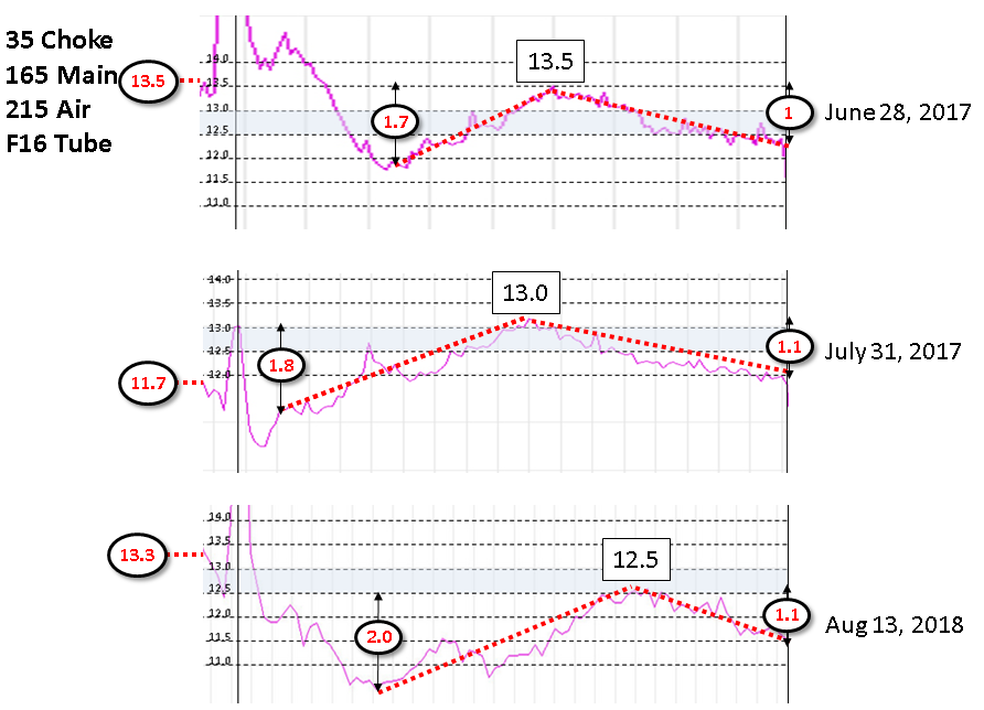
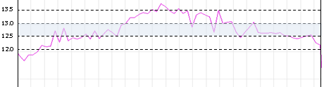
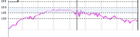
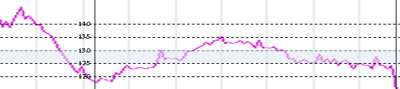
Thanks again for the data. Here are the same F16 165/215configurations captured to date. There is some variance in all so I will have to step back and reconsider what to look for in these plots and all of the others. I overlaid some lines and data points that may be significant. Please double check my assumptions: 1. The left most a/f (13.5, 11.7, 13.3) is at cruise before punching WOT. It seems to vary. It could be related to atmospherics or velocity. 2. The WOT peaks (13.5, 13.0, 12.5) occur at different points on the x axis because the x axis is time rather than rpm. 3. The delta between lower WOT dip and middle-ish WOT peak (1.7, 1.8, 2.0) is fairly repeatable though the slopes change due to the x axis being time. 4. The delta between lower middle-ish WOT peak and the highest WOT point (1.0, 1.1, 1.1) is fairly repeatable though the slopes change due to the x axis being time. 5. The peak A/F in the middle WOT hump (13.5, 13.0, 12.5) varies. This is a bit troublesome. It could be related to atmospherics however the range is large.
-
Here is F11 155/185 Here is blink comparison of F11 155/185 to F16 155/185 No big change in shape between the tubes 8.2mm F16 is ~ 0.5 point leaner across the band I checked with one F19 supplier. Price is high. I'll try to find another or make custom 8.2mm tubes on my lathe.
 Thanks a million for that F11 data! We do not have much on that. I'll plot the data now. For the DCOE throat to manifold runner, that is fine. I just wanted to ensure there was no step from large diameter to smaller.
Crusty!
I just took the EFI harness off my 77 and there is also a ground in the engine compartment the drivers side strut bulge. I missed this one in the drawing above.
Does it require hydraulic tensioners or can the mechanical adjusters be used on that head?
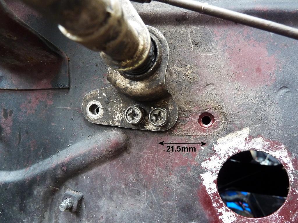
I had to move that part above when putting SU's on my 280z. Only the two outside 3 holes are used on the 280z. The unused middle hole aligns perfectly with the left most captive nut the when moving the part to align with the SU intake.
Thanks a million for that F11 data! We do not have much on that. I'll plot the data now. For the DCOE throat to manifold runner, that is fine. I just wanted to ensure there was no step from large diameter to smaller.
Crusty!
I just took the EFI harness off my 77 and there is also a ground in the engine compartment the drivers side strut bulge. I missed this one in the drawing above.
Does it require hydraulic tensioners or can the mechanical adjusters be used on that head?
I had to move that part above when putting SU's on my 280z. Only the two outside 3 holes are used on the 280z. The unused middle hole aligns perfectly with the left most captive nut the when moving the part to align with the SU intake. Been there with a friend's tank that had a loosened vent port. We used a lot of flux and plumbing solder to repair.
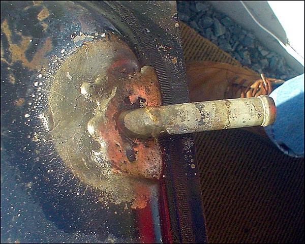 I agree with CM. Often there are car club members who are qualified and licensed inspectors. Call the executives of local car clubs (vintage Chevy, British, Porsche, etc.) to see if you can find one.
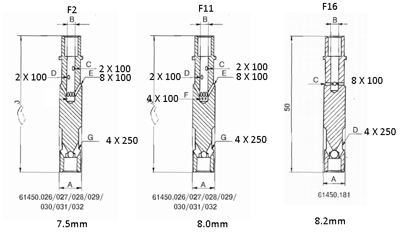
Here is interesting F16-like E-tube at 8.2mm but with deeper internal cavity and more drillings. It also continues its fat 8.2mm thickness nearly to the top so no puddle of fuel outside the tube at cruise or start of acceleration. Maybe this puddle is what causes the very rich burst at the start of the runs right after the gasp? It is the same puddle for all 3 tubes we have tested so far. i.e. this puddle is gulped at start of WOT run and is not emulsified very well causing the rich dip in nearly every 45DCOE A/F plot. Maybe the F19 it can change the curve shape and flatten the hump as it is significantly different from F2/F11 AND because it does not have a thin region near the top where a fuel puddle can occur between the well wall and the side of the jet? I'll try to source 6 of this strange e-tube.
I agree with CM. Often there are car club members who are qualified and licensed inspectors. Call the executives of local car clubs (vintage Chevy, British, Porsche, etc.) to see if you can find one.
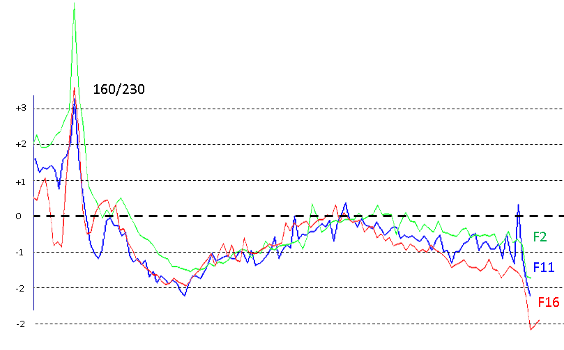
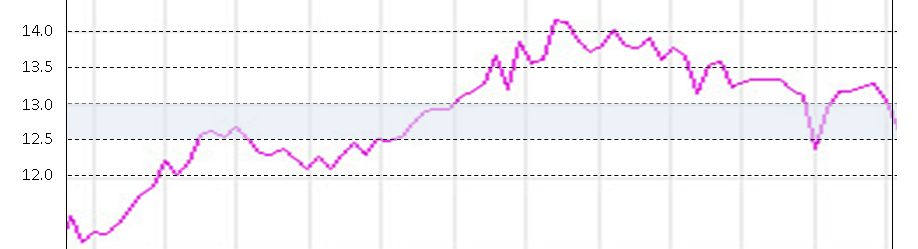
Here is interesting F16-like E-tube at 8.2mm but with deeper internal cavity and more drillings. It also continues its fat 8.2mm thickness nearly to the top so no puddle of fuel outside the tube at cruise or start of acceleration. Maybe this puddle is what causes the very rich burst at the start of the runs right after the gasp? It is the same puddle for all 3 tubes we have tested so far. i.e. this puddle is gulped at start of WOT run and is not emulsified very well causing the rich dip in nearly every 45DCOE A/F plot. Maybe the F19 it can change the curve shape and flatten the hump as it is significantly different from F2/F11 AND because it does not have a thin region near the top where a fuel puddle can occur between the well wall and the side of the jet? I'll try to source 6 of this strange e-tube.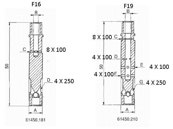 In comparing the 3 E tubes with the same main and air (figure 1) the shapes are not very different however the a/f offset seems to match the tube's diameter. The F16 is a fat tube at 8.2mm and blocks off most of the well. This seems to cause a leaning across the full band The F11 is a medium diameter tube at 8.0mm The F2 is a thin tube at 7.5mm and does very little blocking/braking The F2 and F11 E tubes 2 have nearly the same drillings in the side and have may more up-higher than in the F16 however the curves do not seem to be much different. - The f16 does dip more into richness as it approaches 7000rpm - The F2 is richer at cruise before the lean gasp spike - The lean gasp spike is similar in magnitude for all 3 tubes [Figure 1] In figure 2 below, the plot for each tube is normalized to the middle lean peak. Using this technique we can see the subtle relative differences: [Figure 2] There is minimal difference between the 3 tubes. The F16 (with fewer high drillings) drops off more in the higher rpm range The F2 is the flattest after the gasp up to 700orpm. It also dips the least after the gasp. The F2's lean gasp is largest and cruise a/f is leanest relative to its WOT a/f The F16's cruise a/f is richest relative to its WOT a/f From this data it seems: Fewer holes up top in F16 causes the very high RPM range to get richer The difference between cruise a/f and WOT a/f seems to be proportional to tube diameter rather than drillings. A fatter tube brings the two closer Drilling some holes in the top of F16 e-tubes may reduce the highest rpm dip. Comparison of E-tubes:
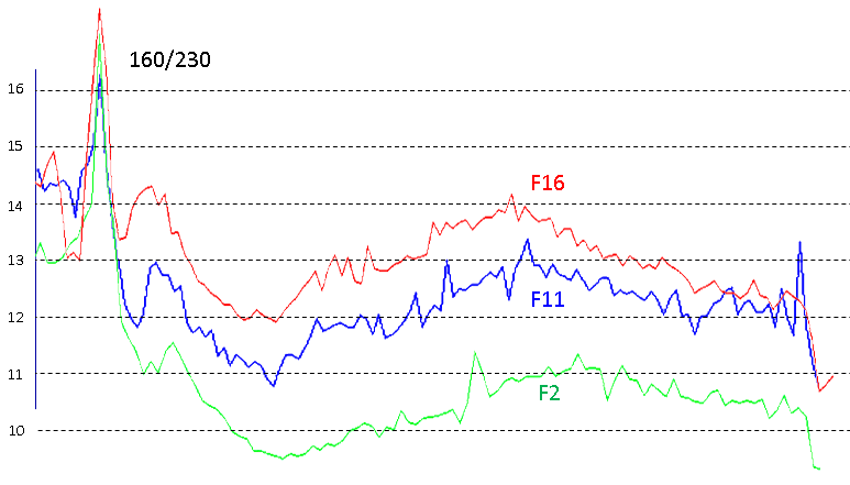
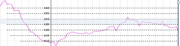
 Here is your F16 155/185 flat run from last night. Here is the next previous F16 155/185 Here is your very first run with F16 155/185 and 34mm choke from last October My thoughts: There is some variation due to the time being the x axis rather than rpm however the same max/min signature is seen. It seems this combination of 155/185 gives nice results with F16 Etube. A main jet in the 165 to 150 range seems to be where to hover. We were unable to change the high rpm tilt/drop off by opening the air corrector. When we tried, it leaned too much elsewhere. We were unable to change the low dip when the accelerator circuit kicks in. Due to the two items above, all of the runs had a lean hump in the middle for which the edges could not be modified to meet nor could we beat down this lean hump. The very low dip into the 10's and 11's when the main circuit kicks in is always present. It is independent of emulsion tubes, acceleration jets, bleed back valve, or fuel level. This gorilla in the room seems to be due to the 45mm carb as it appears in many other 45 applications that are not L28's. I think the only way to deal with it will be modifying E tube tops. Of all the runs, the F16 165/215 seemed to have the least dip at the start of the run. This may be the best compromise. Here it is: And here is your F16 155/185 run from last night where it dips below 11: Going forward: A run with the 155/185 with the F11 tubes would be a "nice to have". The low dip at the start may be due to the emulsion tube unloading liquid fuel at its onset (We proved it is not acceleration circuit or Etube or Main Jet or Air corrector, or fuel level). If you are up for it, some modifying of the top holes of the F11 tubes would help confirm if there is a way to tune this region. If the low dip at start can not be tuned with modified E-tubes then it is simply due to the 45 DCOE design being incompatible with the cylinder size. A 40DCOE may be a more appropriate carb for tighter controlling a/f ratio. Question: 1. Is the 45DCOE output diameter port-matched to the intake runner's opening or is there a step from a large 45mm dia carb to a smaller diameter intake port?
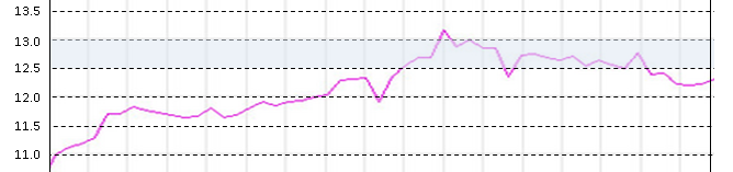
 Here in NS you can get the car registered as an Antique Car. No requirement for safety. The only negative aspect is that insurance for Antique plates only covers you on to/from car shows/ car club events, or to service sites. Our club used to have club rides every summer weekend to allow us to drive more and maintain the coverage.
@Maritimer Where are you in NS? I'm in Hammonds Plains.
Here in NS you can get the car registered as an Antique Car. No requirement for safety. The only negative aspect is that insurance for Antique plates only covers you on to/from car shows/ car club events, or to service sites. Our club used to have club rides every summer weekend to allow us to drive more and maintain the coverage.
@Maritimer Where are you in NS? I'm in Hammonds Plains. Congratulations on marriage!
Remember to chase all of the bolt holes and clean them thoroughly. You can do it in these steps: 1. Pour solvent in each bolt hole then use a wire gun barrel brush or similar. 2. Run bottoming tap to chase threads 3. Brake cleaner sprayed into the bottom of the bolt hole with a shop rag muffling the top of the hole. After that, wire brush the head bolt threads, oil them, then test in each hole. Be sure to oil the washers too.
Hi Chris and Charles, My good buddy @Dr. 240Z gave me two U-Joints. They say: MFG: Kawasaki Part: 578234 Ref: ATV700 I hope this helps!
Congratulations on marriage!
Remember to chase all of the bolt holes and clean them thoroughly. You can do it in these steps: 1. Pour solvent in each bolt hole then use a wire gun barrel brush or similar. 2. Run bottoming tap to chase threads 3. Brake cleaner sprayed into the bottom of the bolt hole with a shop rag muffling the top of the hole. After that, wire brush the head bolt threads, oil them, then test in each hole. Be sure to oil the washers too.
Hi Chris and Charles, My good buddy @Dr. 240Z gave me two U-Joints. They say: MFG: Kawasaki Part: 578234 Ref: ATV700 I hope this helps! Here is your second last run: 35 Choke 140 Main 240 Air F2 Tube Here is your last run: 35 Choke 140 Main 185 Air F2 Tube Decreasing the air from 240 to 185 significantly lowered the a/f in the first 3/4 only (It scooped the middle a bit too). It seems the top end is controlled more by the fuel jet. Please try the 225 air and 150 main. For the lean spike, I am not sure if it is controlled by the 00 spill jet. You can try a bigger accelerator jet to get more fuel to squirt earlier.
 These work great for 22awg water proof connections. The good ones have silicon gel in them: I used to make circuit boards using surface mount technology and solder paste was used. It was deposited with a syringe. A high temperature vapour was used to melt and flow the solder.
I spray both sides of the gasket with copper coating from permatex
Time to celebrate! An appropriate song: Head On! https://www.youtube.com/watch?v=cXn1gZOk1kk
Double check these areas with your fingernail, it looks like some ring-to-wall interaction took place at one time. It could be simply lighting in the photo .
These work great for 22awg water proof connections. The good ones have silicon gel in them: I used to make circuit boards using surface mount technology and solder paste was used. It was deposited with a syringe. A high temperature vapour was used to melt and flow the solder.
I spray both sides of the gasket with copper coating from permatex
Time to celebrate! An appropriate song: Head On! https://www.youtube.com/watch?v=cXn1gZOk1kk
Double check these areas with your fingernail, it looks like some ring-to-wall interaction took place at one time. It could be simply lighting in the photo .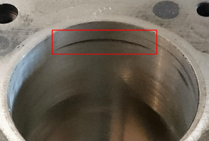

Important Information
By using this site, you agree to our Privacy Policy and Guidelines. We have placed cookies on your device to help make this website better. You can adjust your cookie settings, otherwise we'll assume you're okay to continue.