Dave WM
Free Member
-
Joined
-
Last visited
Everything posted by Dave WM
-
 nice fix! interesting about the diodes, when I looked at the schematic. At 1st I thought they were for flyback voltage spike protection from the coils, but the way they are wired it seems more like just a reverse polarity protection (looks like coil current is blocked if reversed voltage applied). If that diode works I wonder how come peeps keep frying ECU's when connecting up backward? Maybe I am not looking at it right... Ok so Pin 4 on the ECU is NOT diode protected (gets 12v when in "start") and Pin 47 also gets a shot from "Start" CSV which goes back to the ECU as well on pin 21. this is a 1975 fyi. on my DIY 300zxt harness I did NOT use them (diodes) as polarity protection but did wire in P with the coil for flyback protection. Just have to not get stupid when connecting the battery.
 -
just to clarify the ease part, IIRC after removing all the drive shaft stuff so you can clearly see the tunnel, use a trans jack to support and then remove the rear mount. lower the trans (best to have removed the rad or at least have someone keep an eye on it so as the engine tilts back you do not have a fan blade dig into the rad core), until you can clearly see the shifter pin. You will have enough room to get in there with a pick and remove the circlip, pull the pin, pull up from the inside of the car the shifter, and get it secured so it does not impede the rest of the work. installing a trans with the engine in is a hit or miss prob as far as the hassle of getting the input spline to align with the clutch plate. I like to use some long bolts with the heads cut off as guide pins (I cut slots in the top to allow for a screw driver to be use to remove the bolt once trans is fitted), one on the top and one on the bottom opposite side. This lets you get the trans clocked right and in the general position. from there it's a lot of wiggle, push, swear words, then pop it just goes in. Sometimes you get lucky and it just goes in and you wonder what everybody it talking about it being a PITA. A tip is to put the trans in gear before removing the shifter, this will allow you to twist the output shaft by hand while doing the wiggle/push motion. The idea being IF your spline is just off a hair it may help it align. In reality the guide pins should be sloppy enough to let you twist the entire trans, but if the input shaft is binding up on the clutch and not in the perfect position it may resist moving to align. Being in gear gives you a bit more control over the ablity to align the input shaft. another tip, when tightening the pressure plate make darn sure the clutch alignment tool is going in straight. I can droop a bit from the weight of the friction plate. You should try to aim for a neutral position between the up and down amount of play even with the tool installed. Make sure as you go the tool can be inserted and removed easy. I have done this a few times, like I said sometimes it just pops in so easy you wonder what is the big deal, other times not so much. last tip, make sure the alignment dowels are in place, these keep the trans input shaft perfectly centered, there are 2 diag mounted I cant recall if they go in the block or the trans housing. The fit OVER the bolts in enlarged holes, so the bolts go thru them.
-
yes, its rather easy actually. just once you get the pin out make sure you pull the shifter up and out of the way, it will flop around some but no big deal. You want to avoid having it drop down and get in the way when pulling the trans back off the block. Do note the way the pin goes in, IIRC its inserted from the left side, and has a flat that needs to mate up on the trans housing when reinstalling. Oh and watch that circlip, it will jump out and get lost if you are not ready for it.
-
I would just check for radial play with the drive shaft installed. a little heavy oil on it. if play is not excessive you should be ok.
-
IF you had wanted to get a new bush, omega machine has the correct one, but since you already have cleaned and reinstalled the old one I am just posting for future reference. I don't know why they get so scored up, mine was the same. It looks like you have the oil hole correctly lined up with the oil gutter. On mine the gutter pickup was broken and stuck to the magnetic drain plug. I figured loss of oil was the culprit, but that is just a guess.
-
I have the L28et block, and the knock sensor that goes with it, just not sure its compatible with the 300zxt ecu, very confusing stuff. Prob the smart thing would be to just use the one that it came with (the 800 ohm sensor that keeps creating the error code) and see if it knocks in use. From what I have found so far is the knock freq is about 6.5k and if I go with a flat response sensor (not tuned just outputs AC at what ever freq it sees when vibrating the piezo crystal) in order to get any usable info from it I would need a narrow bandwidth, prob an active filter. Since for now I am sticking with the OE ecu from the 1986 300zxt my options are pretty limited as far as tuning. The best course of action really seems like just install the thing and see how it runs....
-
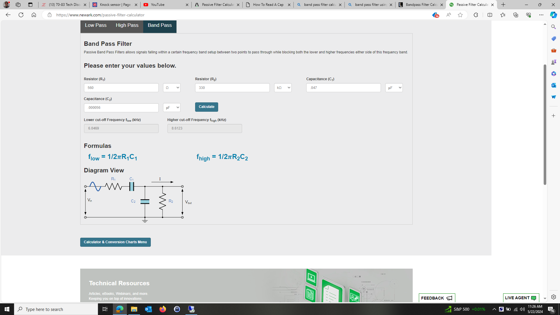
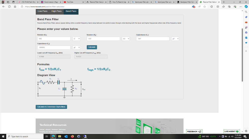
having a bit of an issue getting a knock sensor that will work with a 300zx turbo 1986 ecu and an L28et block. found a sensor from nissan but when I looked at the scope with it installed on the running engine I was getting all kinds of voltages that I would assume be problematic. My guess is the flat response vs resonate is the issue. Pretty sure the doughnut type I am using is a flat response type. the rc value was selected since the ecu seems to want a specific value to not set a code, there is a bias voltage that is dropped by this resistance. The r1 was selected as I assumed the lower value would pass more signal. The stock sensor in a L28et has a resistance of about 750 ohms, which sets the error code. Left disconnected (infinite) also sets the code. I used the nissan senor that was about 500k and no code. will try the 330k and see, if not will adj up to the 500k and reset the C2 that C2 56pf seems like a very small number for any kind of audio frequency, but that is what the calculator called for with the R2 value. so here is my next try...
-
it may have something to do with the quality of the gasket material re the use of sealants. That and how well you prep the surfaces, that is get all the remnants off and NOT gouge anything in the process. I have used the aviation sealant, just a very fine amount, with no leaks. I do not like RTV for anything except a tiny bit on the seams where the FSM specifies. One thing that really sticks out in my memory is the front cover around the water passages. The connection from the front cover where the pump resides and the block carries water, a leak there is internal into the oil pan. IIRC the FSM calls for a sealant there but maybe wrong on that one. Def an area you want to be sure on. There looks to be a weep hole and water channel around this same area machined into the inside of the front cover. I presume the design is to allow for any seepage from the junction of the cover to the block to have a way out before getting into the oil pan. This channel around the water passage has a small exit hole just visible on the front cover under the water inlet. A small rectangle hole. I know from experience that incorrect application of RTV (too much) will clog that passage, defeating the purpose. An O ring is more fool proof but that is not how its designed.
-
alignment dowels
-
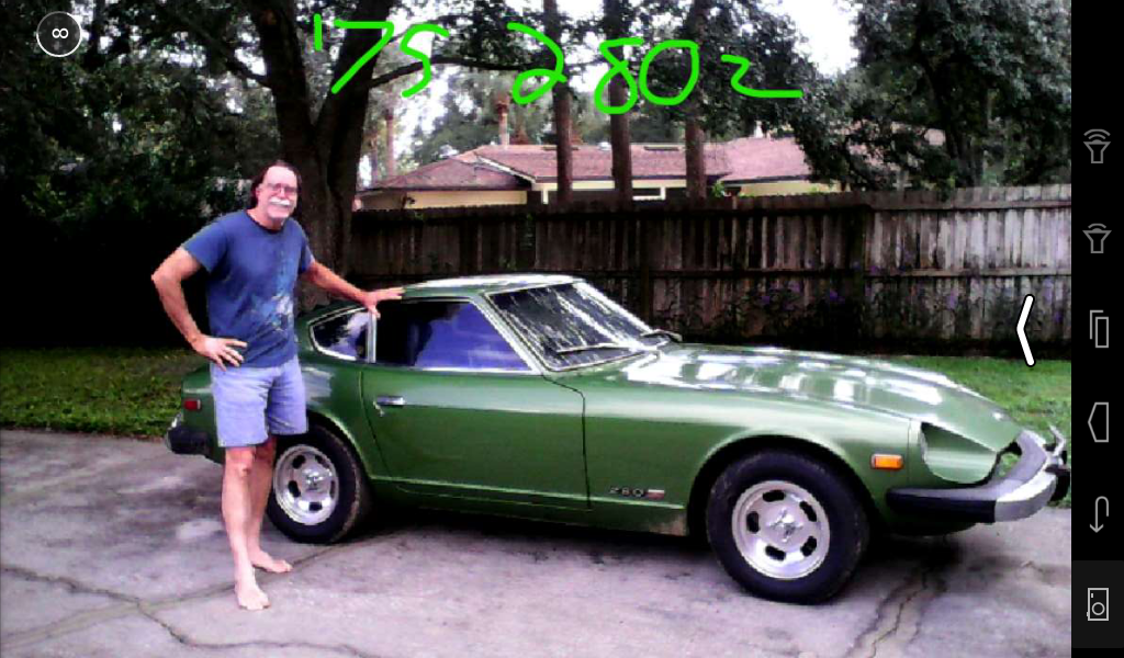
will be doing some more test (I love the test stand for this reason). the plan is to find a correct sensor for a 300zxt and check for fitment to a L28et block, then scope it while running in the engine, compare to the doughnut style I am currently using that does not set the code. See how they compare. I would like to actually see the ign timing get retarded by a simulated knock, I tried using a timing light and lightly tapping the block next to the sensor, could not see any change in timing, but that was at idle, and I have no idea of the strategy the ecu uses. I considered a band pass filter, as seen on another site, think it was hybrid Z, to narrow the freq response to about 6-7khz (the presumed freq created by pinging). Not sure exactly how that would work out, I presume I would just need to make sure I use a terminating resistor to avoid setting a short/open code. Before going down that route it may make sense to just abandon the idea of using the ECU for knock sensing and go with a stand alone knock sense control. anyway just more reason to delay the engine install 🙂 I took a trip recently (800 mile round) it burned about 1/2 quart of oil and I got 27 mpg (mostly AC off) going about 65 most of the time on non ethanol. Not bad for a 50 year old car... Needless to say the car ran perfectly and I did get a few chances to test the speed limits out on the turnpike (going the speed limit is insane there, you will get run over). The car loves to run over 80 mph.
-
videos
-
So does anyone know the correct knock sensor for the 86 300zxt ecu that will fit the L28et head?
-
quick update, I went out to check it again, the loaded voltage with the 280zx sensor was more like .06 vdc not .1vdc. I disconnected the battery to clear the memory and tried the later model KS that was 500k resistance (2.0vdc loaded reading at the sensor when plugged in) and now the code is no longer flashing. I can only assume it still is not going as is a 22060-30P00 or a flat response sensor. I will see about getting the correct resonant type for it.
-
I keep getting code 34, its installed on a 1986 280zx turbo using the 280zx turbo det sensor. I am guessing that is the issue. But would also like to confirm a few things. What is the unloaded voltage supposed to be, I am getting 3.8vdc from the wire harness pin 21 to ground. With a 700 ohm (that is what the 280zx knock sensor ohms out too) the voltage drops to about 100mv or about .1 volt. For fun I used a later model knock sensor (2 wire modern type that ohmed out at 500k) and the voltage drop was to about 2v For those of you that have a 1986 300zxt, I would like to know what the unloaded vs loaded voltage reading you are getting at the sensor. here is a link to the project
-
I am pretty sure I just got new lock nuts for the ones that had you pin them over. prob could reuse at least once IMHO, but I had them so used them. Hardest part for me was getting the counter shaft/main gear cluster in all at the same time, I cant recall the exact sequence other than it was a bit fiddly. that and all the fiddly setup on the press to set things up. I think I used the grey rtv or maybe the anaerobic type. think either would be fine. while you are in there you should look into seals for the shift mech, there are both seals and o-rings involved. help keep the gear oil where it belongs and not on the ball of the shifter.
-
yea the extra bolts I mentioned were for the pressure plate, not the flywheel to crank. the larger ZX uses 9 vs 6 to fix the pressure plate to the flywheel. You should also prob get a new tail shaft bushing, omega machines IIRC has the correct one. the one you get with kits is shorter than stock. Also make sure you get a oil gutter that fixes to the front of the main adapter plate, it catches oil slung from 1st gear and sends it down a long gutter to the tail shaft bushing. VERY important to make sure its in place to get oil back there. Its pretty fragile, and easy to break when separating or attaching the transmission main shell to the adapter plate. You can get them from nissan, have to bend up the end to form the gutter, then just press into place. The tail bush maybe ok, just give it a good visual and check for radial play with the drive shaft yoke slipped in. You will want a press, will help a lot. You can do it with out (seen it on youtube) but I dont like banging on things, esp ball bearings. You need to use normal care about how to press in bearings so as not to load the balls in the races. I like all nissan seals, can still be gotten. Make sure all the open sides of seals face lubricant, IIRC one on the front cover can get confusing. be very careful with sychro assy's then tend to pop apart and send small bits flying, especially the small springs that fit under the engagment dogs. think there is a left hand tread on the main shaft rear. tip, easy way to lock shaft in place is to engage two gears at once. I used a HF puller set to get the rear bearing off, pretty sure my videos have some of this documented. I had to put several pieces together to make it long enough to press of the end of the output shaft. Its not really hard just keep up with the part orintation, especially the front sychro hub , that can go on backwards, the FSM will guide you.
-
Oh and I forgot, does the transmission come with the shifter? if not you may need to look into what it takes to make sure the 4 speed will properly engage esp 5th gear IIRC. there is something about it not allowing the 5th detent to fully engage. easy fix with some minor grinding on the bottom of the shifter. Its well covered in this forum.
-
You are going to need a couple extra bolts for the pressure plate. The throw out bearing collar is a rabbit hole of ideas on what is the correct length.
-
are you sure the metal line back to the tank is not plugged up? mine was rusted solid. You would need to disconnect and blow air thru to confrim. make sure you are only checking the metal line, after the check valve (17). You will see the metal line wrap up along the back of the car to a rubber hose, that is where you want to disconnect it to confrim its clear. The steel lines can rust inside and look fine on the outside, but be completely blocked. On mine I just cut out the metal line that runs along the frame rail, saving the ends (they have a lot of bends that would be hard to duplicate, and the rust was confined to just the low part of the line that runs along side the brake lines), too which I plumbed in some hard plastic line to reconnect the metal ends. works fine. Smells can also come from exhaust esp if the rubber seals around the tail lights and hatch are hard and not sealing. On more thing IIRC there is a restriction device inside the rubber hose on the line that goes to the canister from the metal tank line. I did not see it listed on the diagram, but it most certainly was there on mine. Just a metal plug with a small bore hole drilled in it pushed down the rubber line a ways at the canister line from the metal tank vent line.
-
IIRC it was an early 90's pathfinder. direct replacement only difference is the bottom is sealed but for a large port that is just left open. I presume you could run a large dia hose there if you wanted to relocate but that would be totally not needed since the orig was wide open. If you go to a JY to get one just bring along a mighty vac (hand held vacuum pump for bleeding brakes) and make sure the control line will hold a vacuum. As to whether or not this will solve the gas smell I have no idea. It may solve a non funtioning canister if the canister on you car is not working. May is the operative word, as to how it works
-
I guess the only issue is if the pin 108 is a duty cycled ground vs just a resistive load to drop the current to the pump ground, with the duty cycle based on various engine operating conditions. If that were the case my relay may get "buzzy"... for that I could install a capacitor to smooth out the buzz.
-
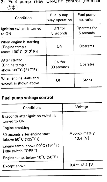
and here is the logic for pin 20 as well as the resulting voltages table. I am not interested in the low voltage operation so I figure the 108 is always working as a ground to operate the pump, my way is just use it as a relay signal (voltage drop across the relay coil should not be a factor) to trigger a switched B+ to feed the pump.
-
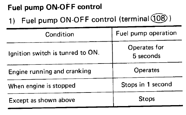
this is the logic table for pin 108
-
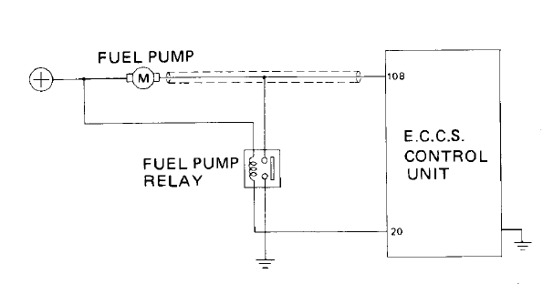
I plan to use a 1985 turbo ECU on my 280z. I am custom building a wire harness. Thing is the OE Z31 uses a switched ground for the pump. The S30 uses a switched positive. I want to make this a plug and play as possible, which mean using the under dash 4 pin plug that feeds the switched positive to the pump. Below you can see how the ECU has constant power to the pump with a selectable ground. One ground is thru a relay (full pump power) switched by pin 20, the other ground is thru the ECU (pin 108) which has a voltage drop across it. My plan is to just use the pin 108 to control the relay coil ground and configure the relay as a normal switched battery positive. The logic table indicates pin 108 is active all the time so this should work. Just wondering if anyone as tried to mod the 85 ECU in this way.
-
The problem I have is lack of documentation on the ECCS ecu's I have. Not sure about the manufacturing date based on the numbers. When I had them apart they all seemed to have the same driver type transistors (total of 6) and seemed to have high wattage power resistors on the boards. I did not try to trace them to see if the collectors were connected to the resistors, or if the resistors were going to the grounding pins on the injector plug of the ECU. the odd ball ones I got off ebay are: A18-000 203 23710 F5910, which seems to be a L20et, not sure how to tell the years. A18-602-045K the last 280zx turbo ecu A18-602 listed on Jim Wolf site was a A18-602-044. so is a 045k ok in lieu of a 044? The one I got with the engine was A18-605-047 which is listed on the JW site as a 83 turbo ecu. it uses the same type of output transistors and I see the same power resistors on the PCB. Based on a cursory examination of the PCB's the layout and parts look similar to the unlisted ECU's. That being said they all work and seem to throttle well, but i have not tested them with the engine under load, just blipping the throttle. I have no idea what mapping is used or if it would be ok. Regardless the seller was ok with just sending me another unit which should have a PN that crossed directly to the 280zx L28et later model, so will just stand by for that. Will update when it gets here.