Matthew Abate
Free Member
-
Joined
-
Last visited
Everything posted by Matthew Abate
-
 Am I misreading that? I’m not finding anything when I search 22472-n3301.
 -
Yeah, that’s what I was afraid of.
-
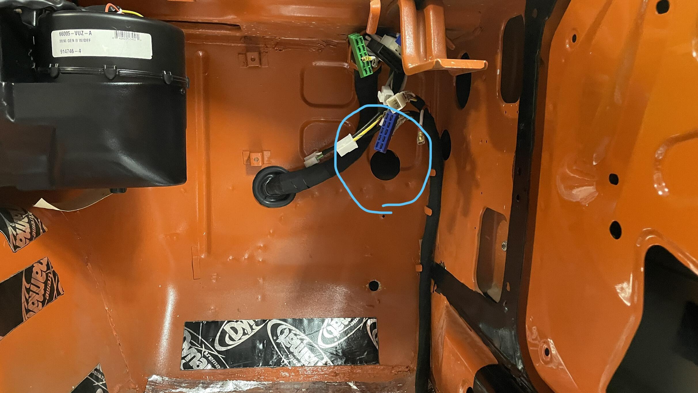
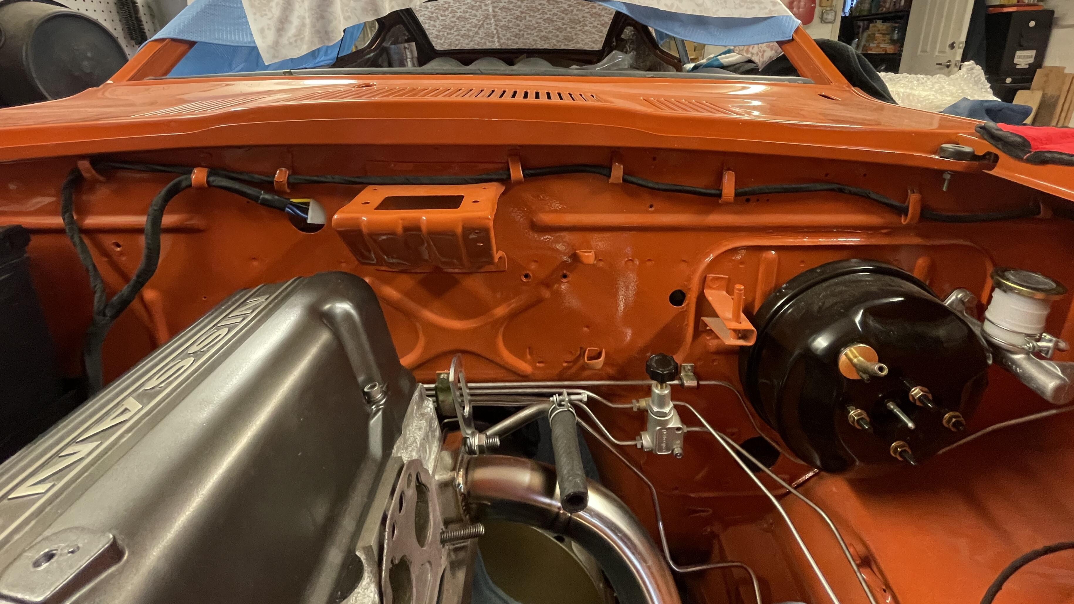
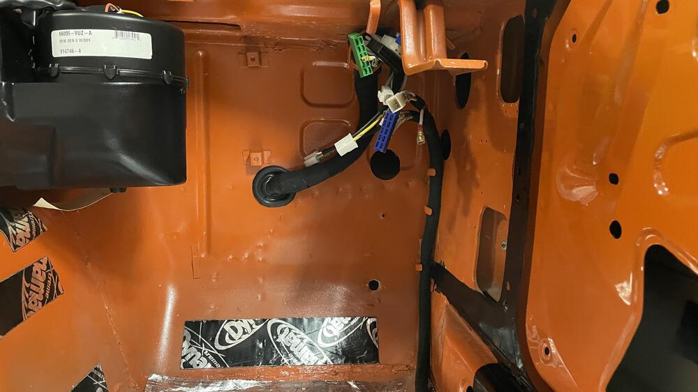
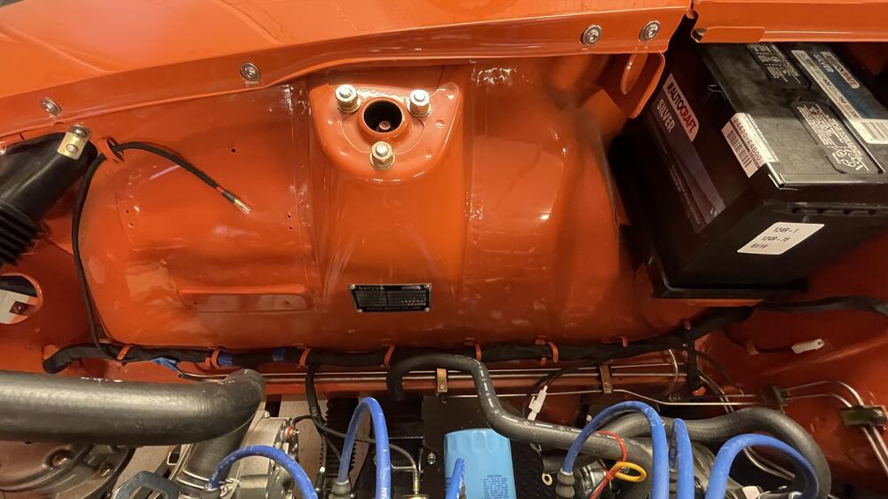
Question: what is this 52mm hole in the firewall under the battery tray for?

-
If it is they have a surplus. It was three days from ordering to parts in hand.
-
Yeah, that’s why I DMed you about it. Using the Toyota description to decipher what you get with that part number is confusing. I got that number when trying to get just the housing, and I think the price is supposed to be for just that, but then I got the whole kit, so ¯\_(ツ)_/¯. What else is interesting is how much other places want. JDM Car Parts has single housings for $189, plus they’re probably RHD and would blind oncoming traffic if they’re actually JDM.
-
81110-60P70 Route 22 Toyota in NJ.
-
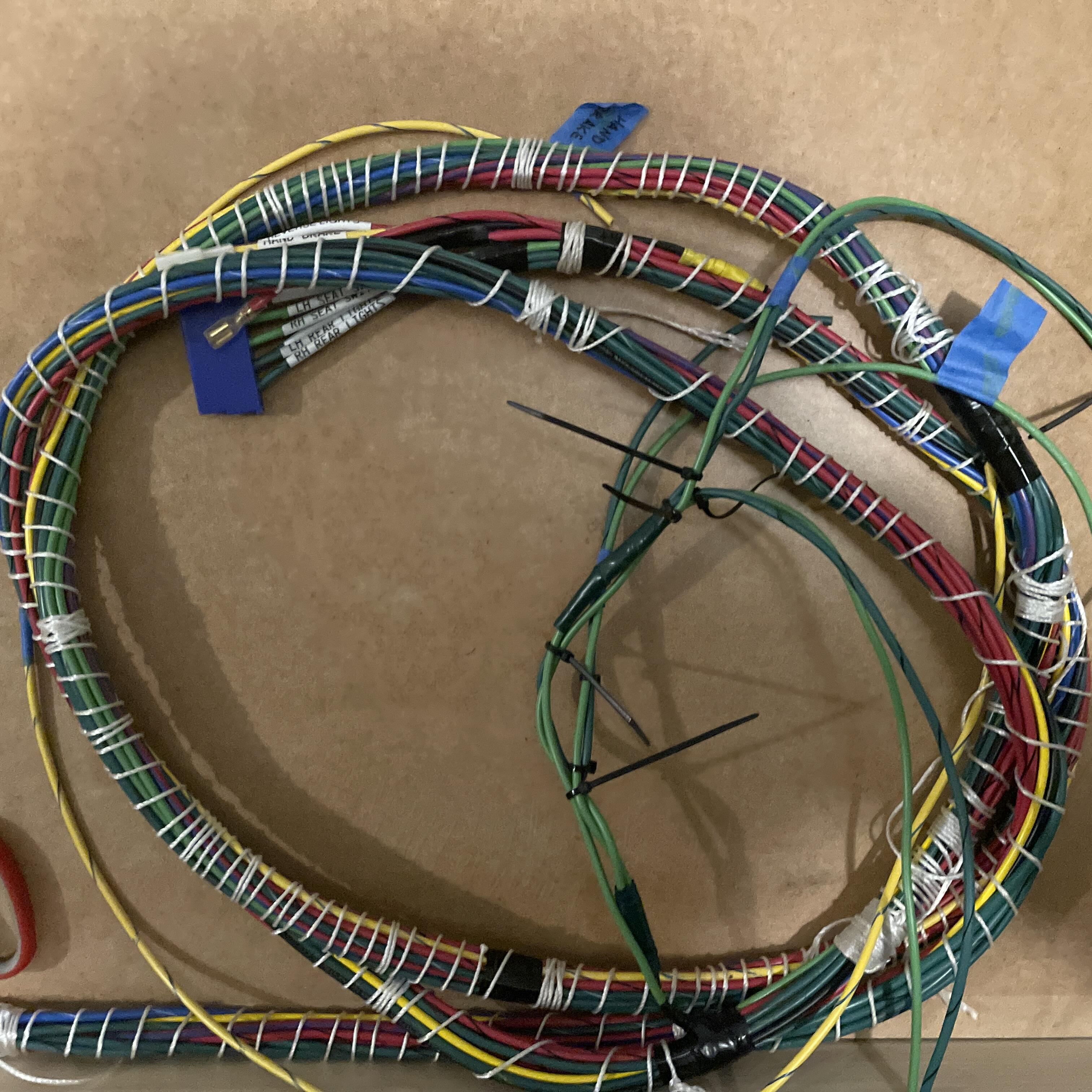
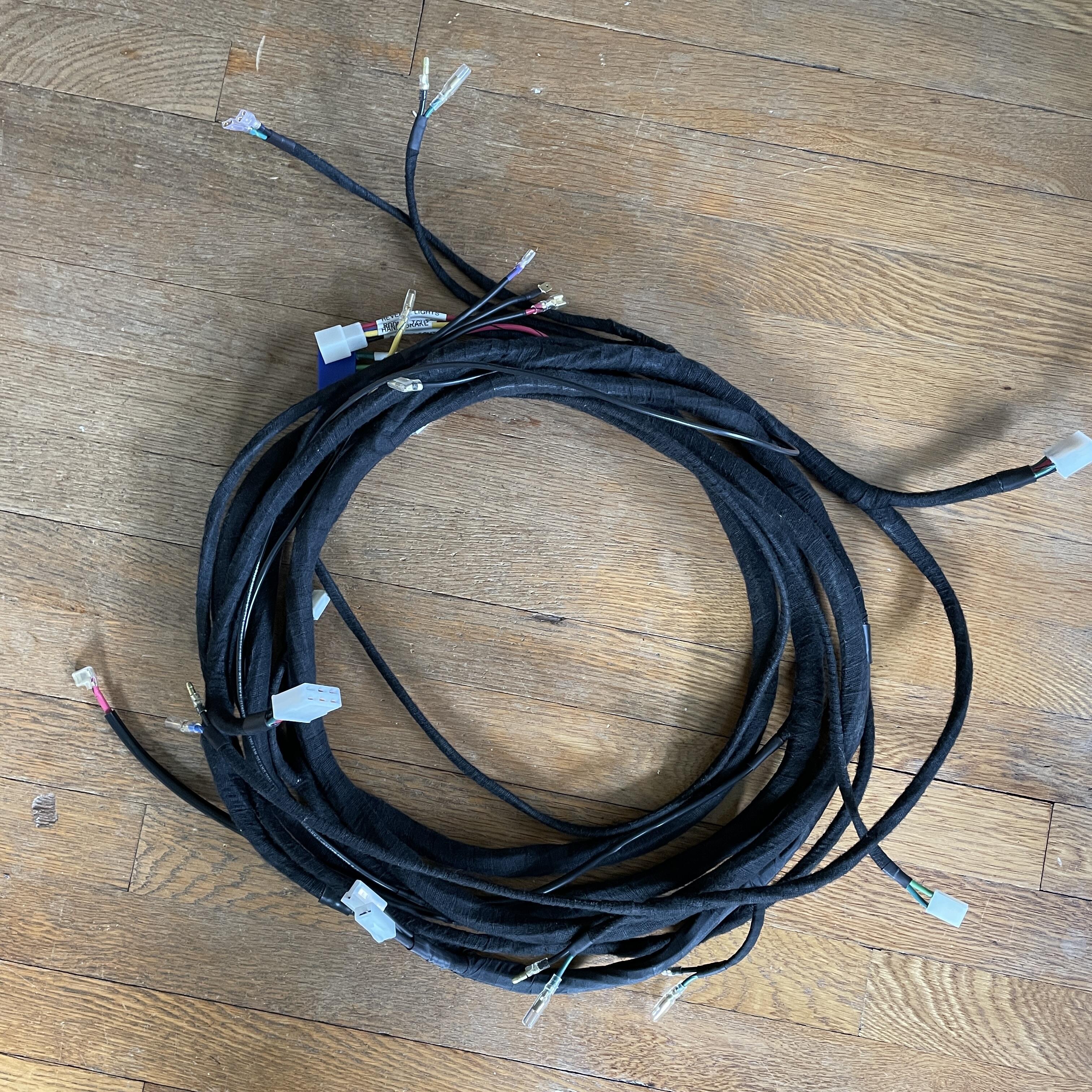
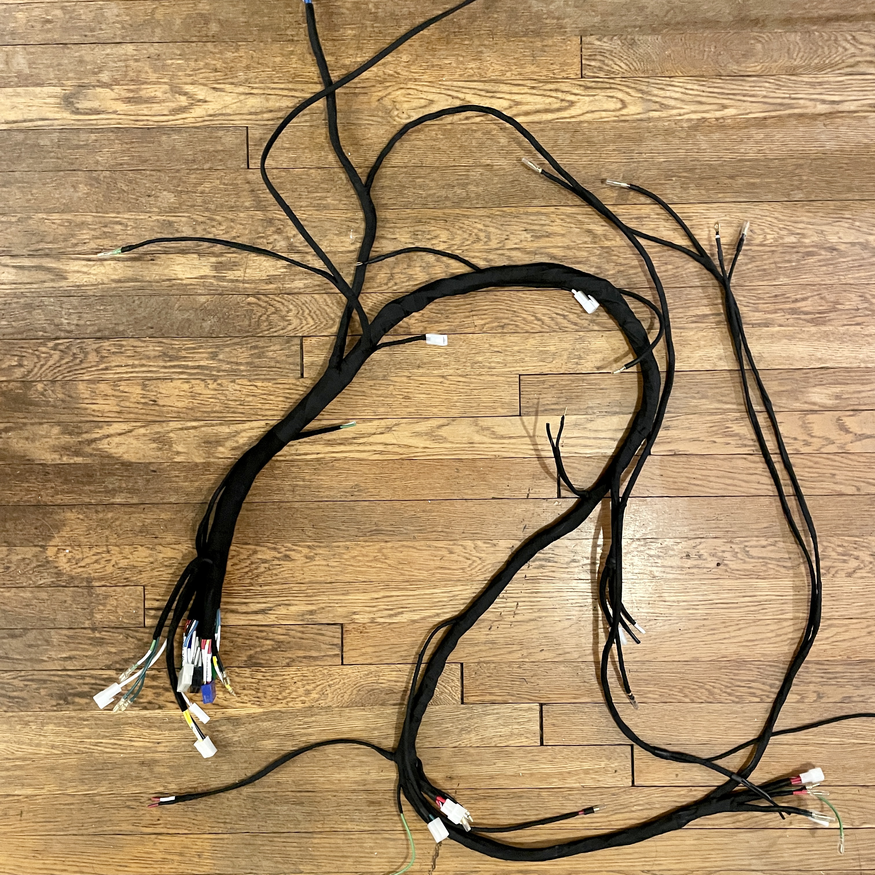
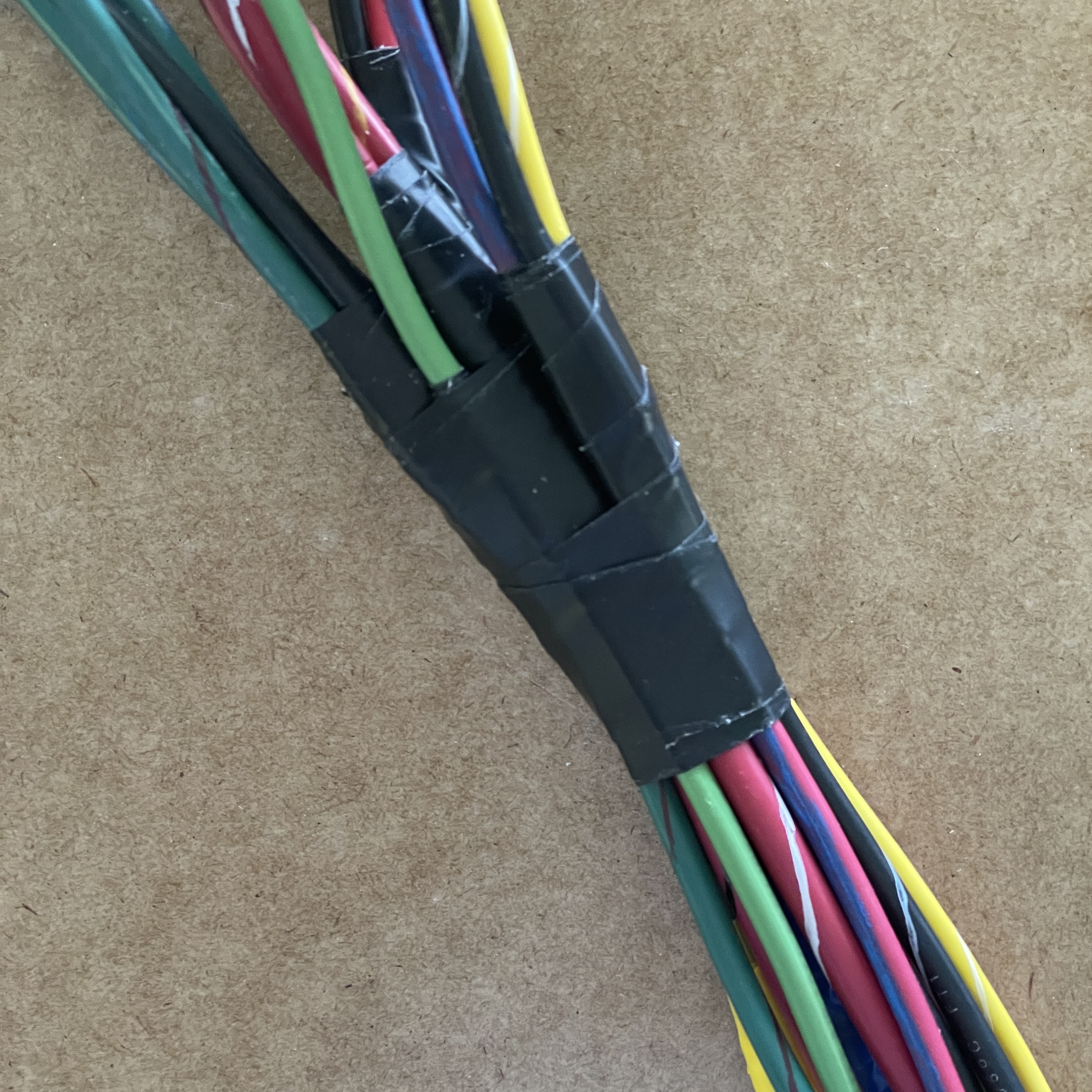
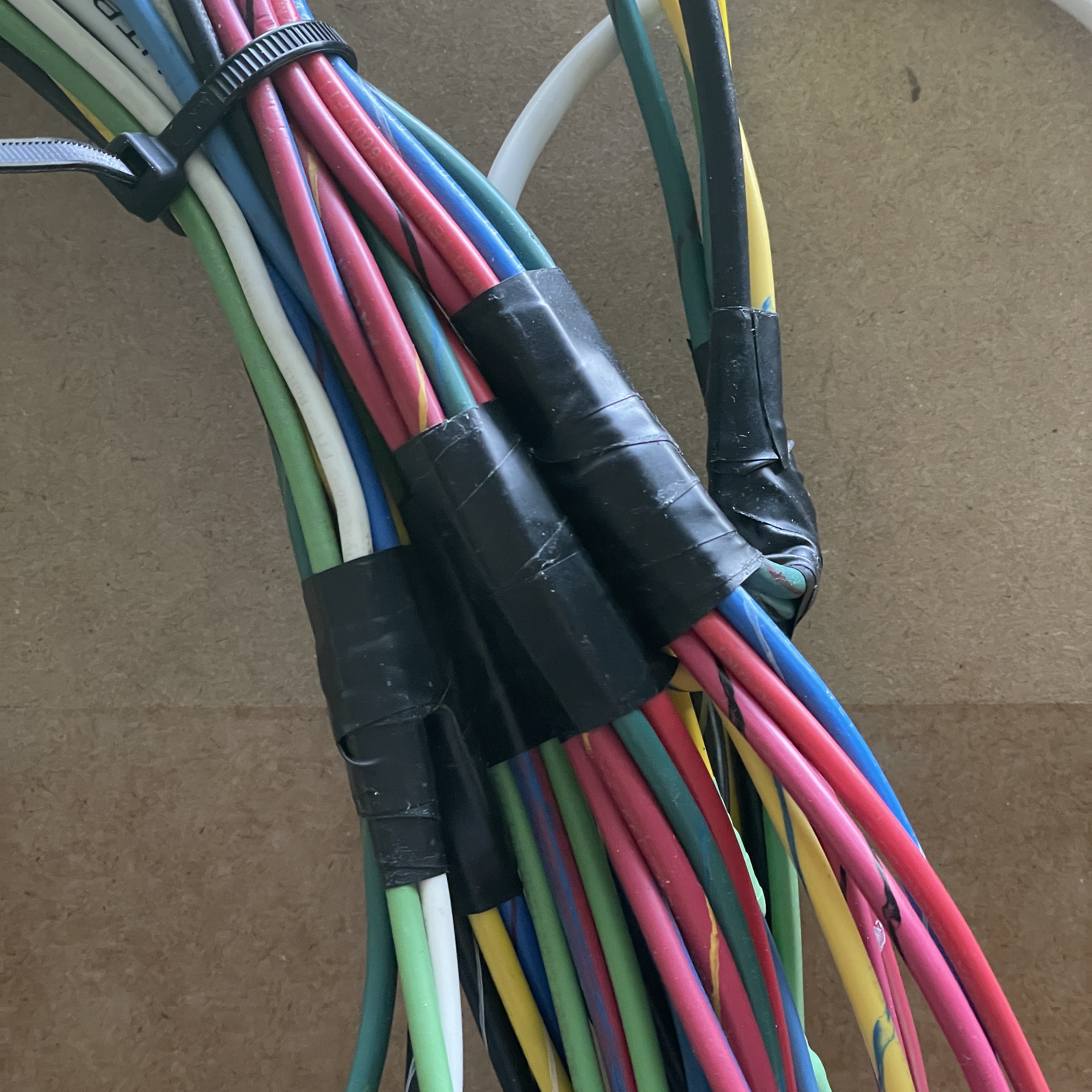
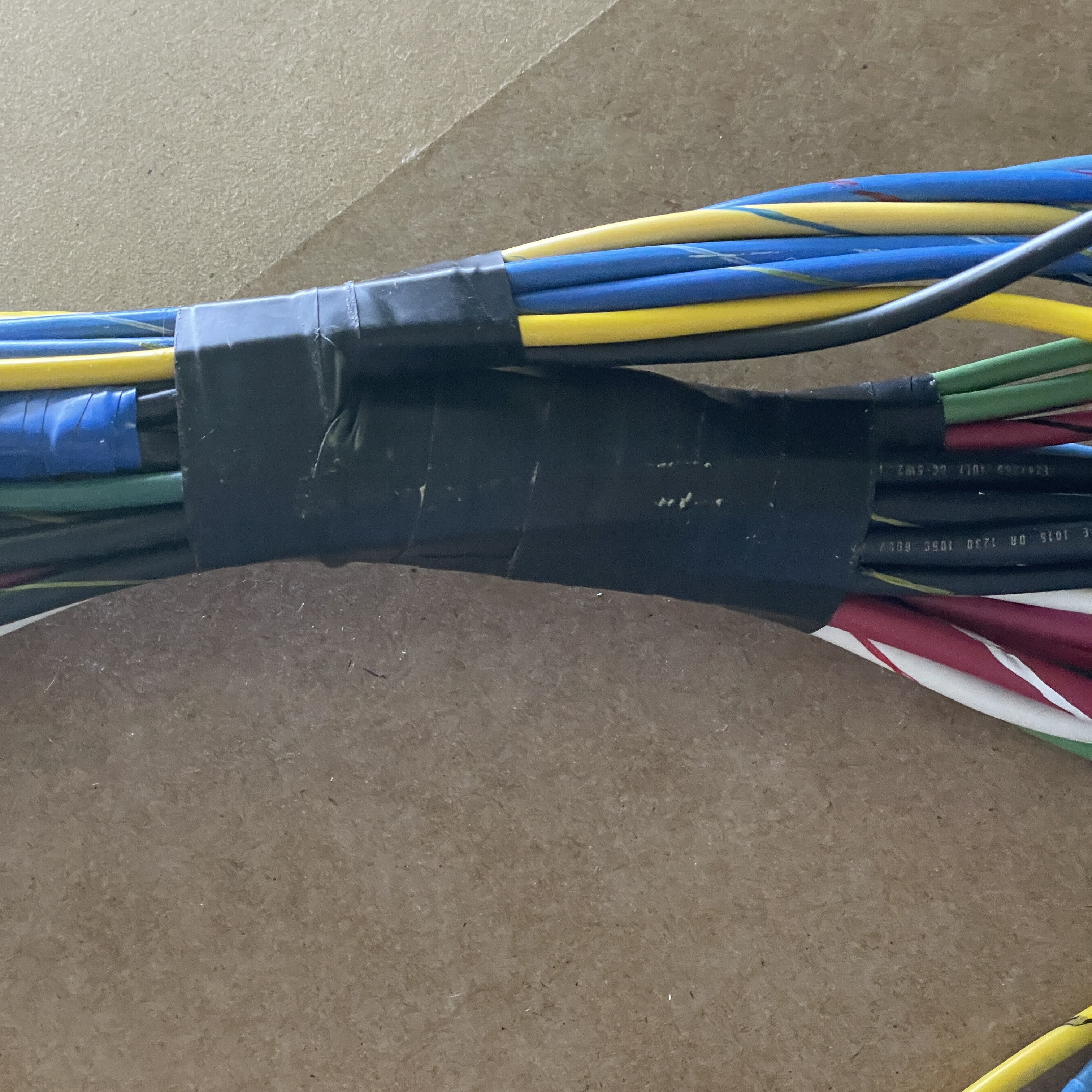
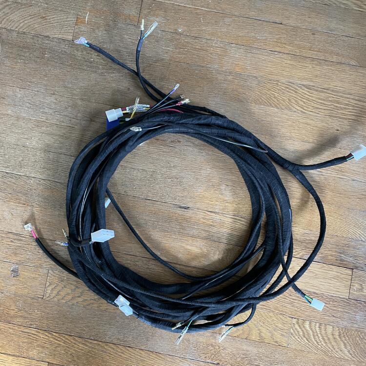
Been a minute, so here’s a progress report: I didn’t take any in progress shots of the body harness as I wrapped it, but here’s the final product, coiled up. One thing I found was that if I wrap the whole thing tightly with string it’s a lot easier to get everything taped off and wrapped in the Tesa tape. I just did the string in the opposite direction so I could unwrap it a bit at a time as I went around it with the tape. I used a harbor freight fish tape to get it in, so it wasn’t a very tough job. $15. I messed up my measurements for the light and defroster wires somehow, but thankfully they’re about 18” too long, rather than too short, so I can cut them down and redo the terminals. Just need to get another set of 90° 6.3mm terminals for the defroster. Oh! And a 52mm blanking grommet for that hole under the battery.


-
Price update: I just picked up a set from my local Toyota dealer for $17.34. $35.44 after shipping and tax.
-
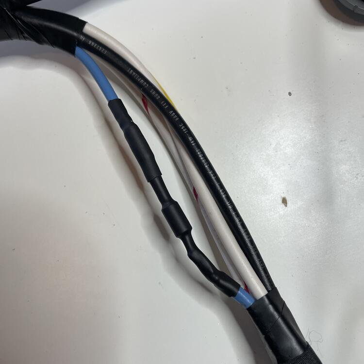
Finally done with the body harness. In addition to deleting the wires for the speaker and antenna, added a provision for some kind of third/auxiliary brake light next to the license plate light wires, switched to a euro/JDM wiring configuration for the rear combination lights, and added wires for a 12V power supply. Also, I used fuzzy Tesa tape for most of it to reduce potential rattling and their chemical-proof tape near the fuel system, just in case.

-
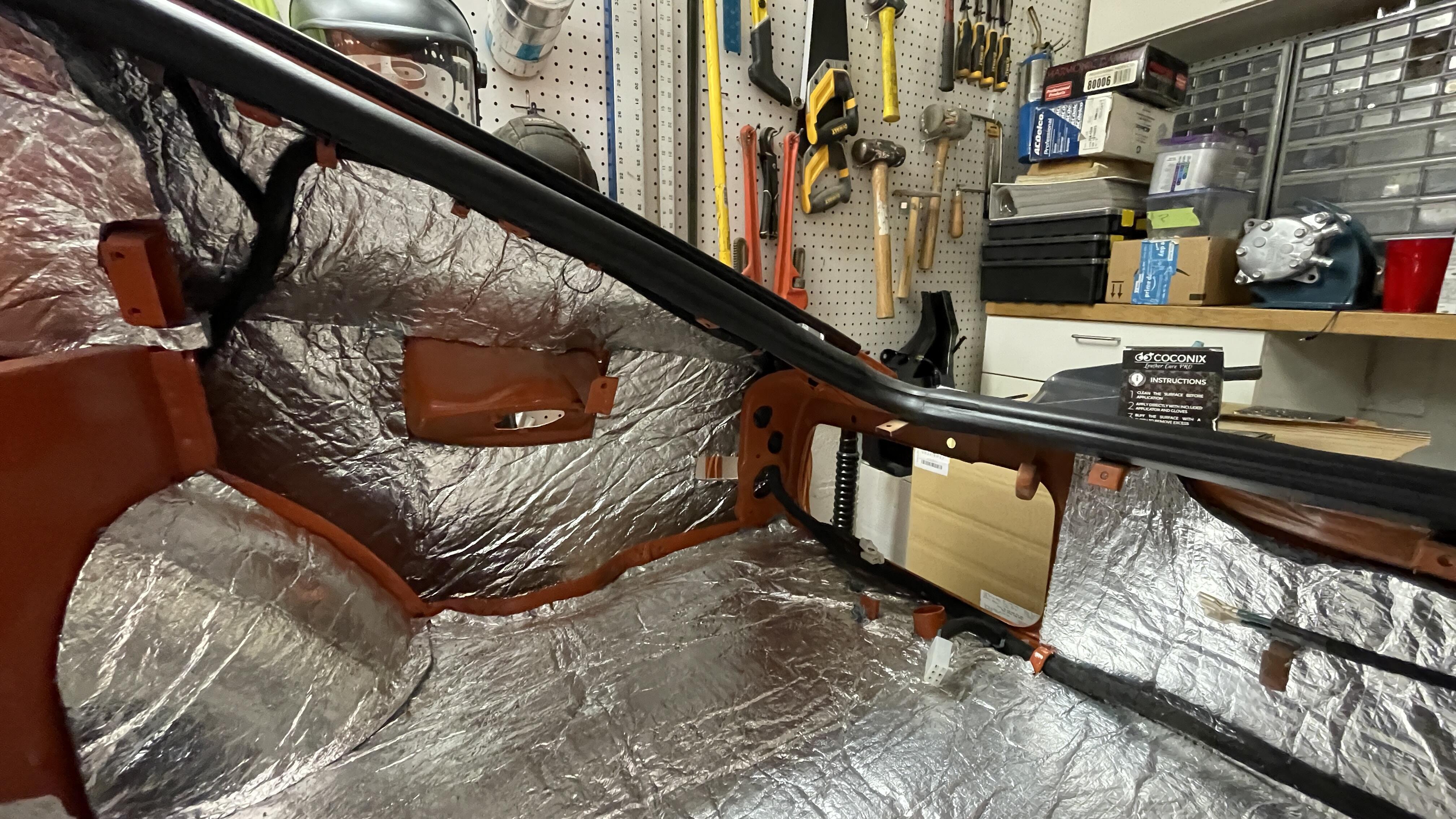
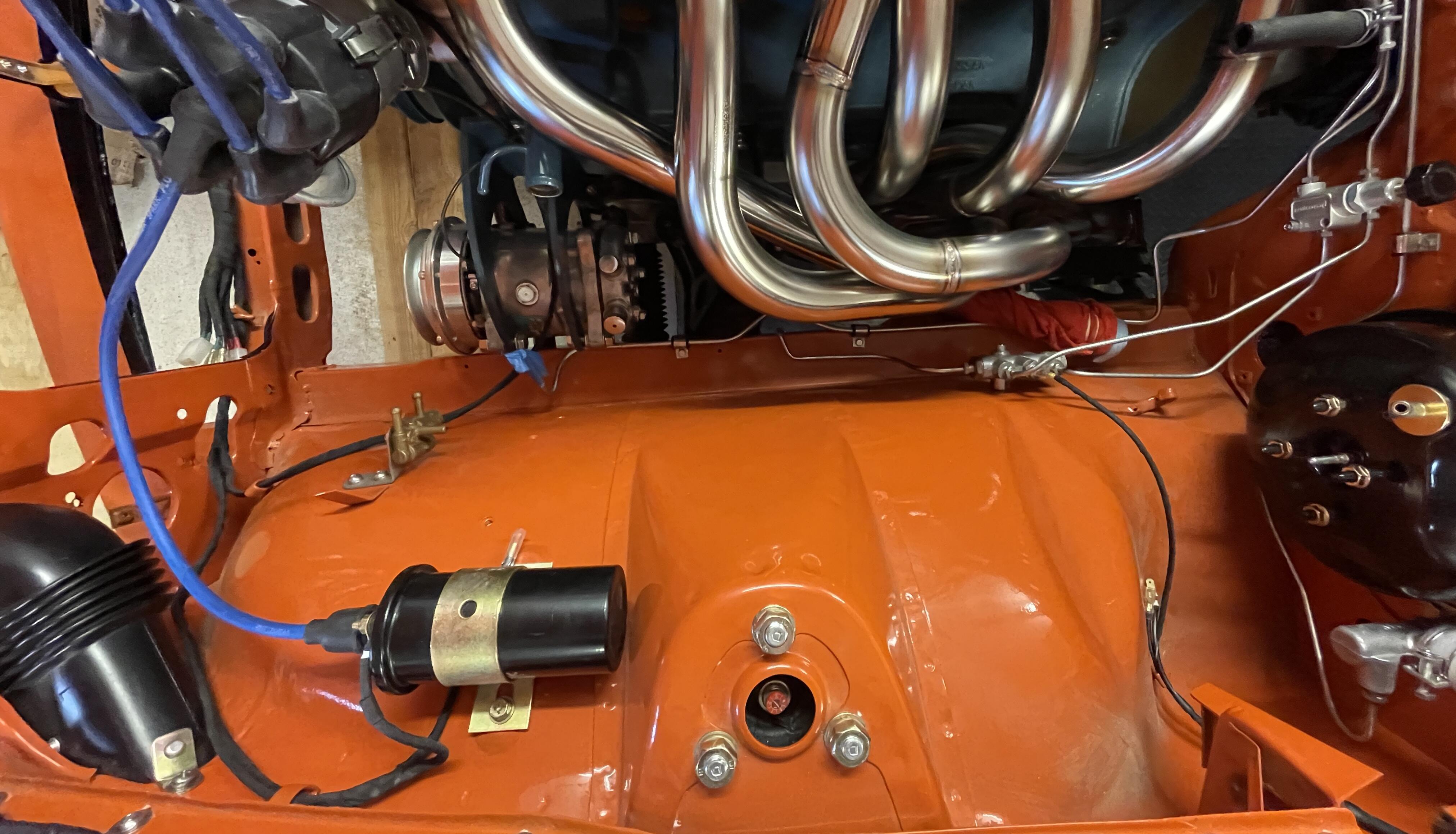
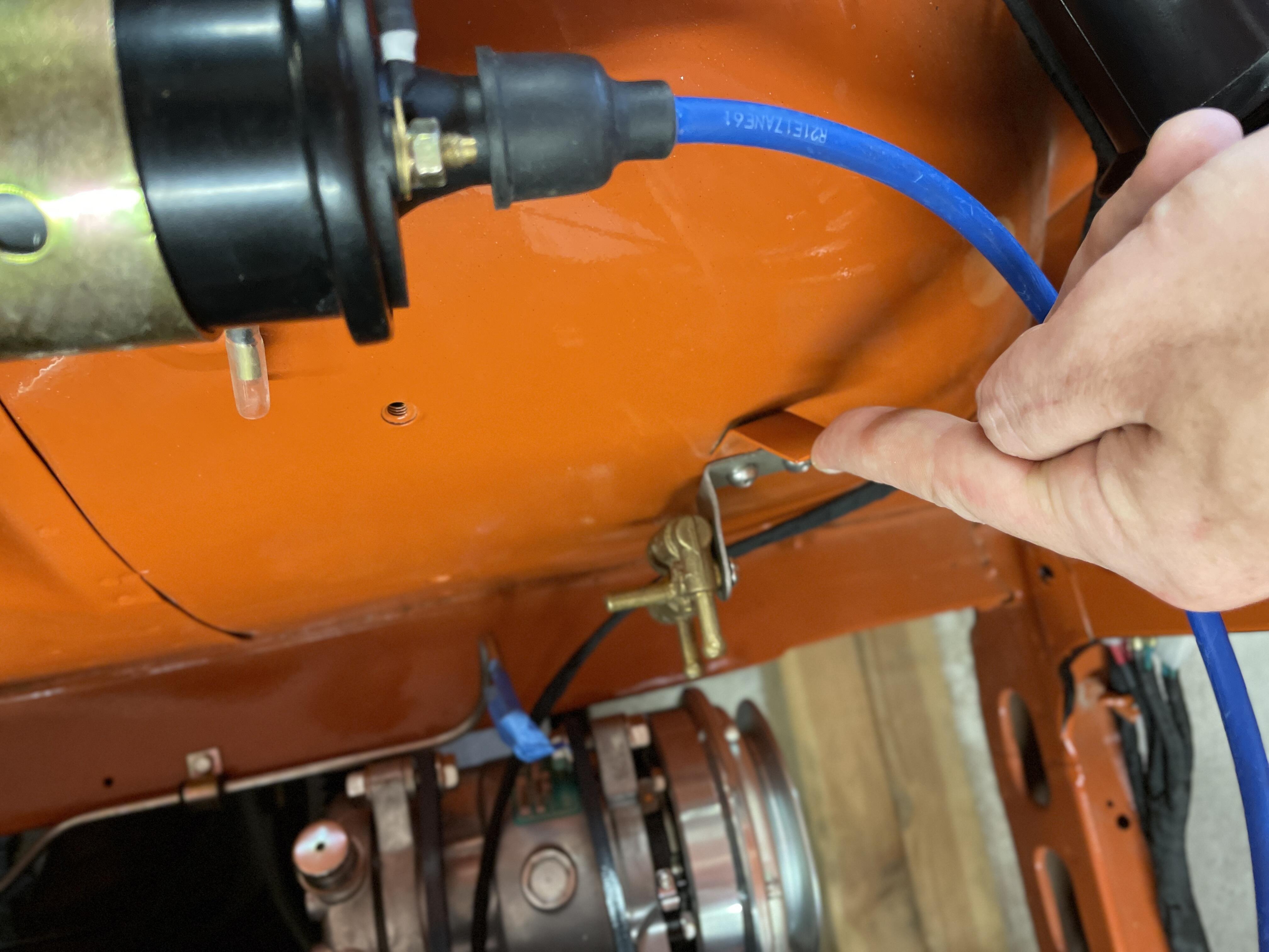
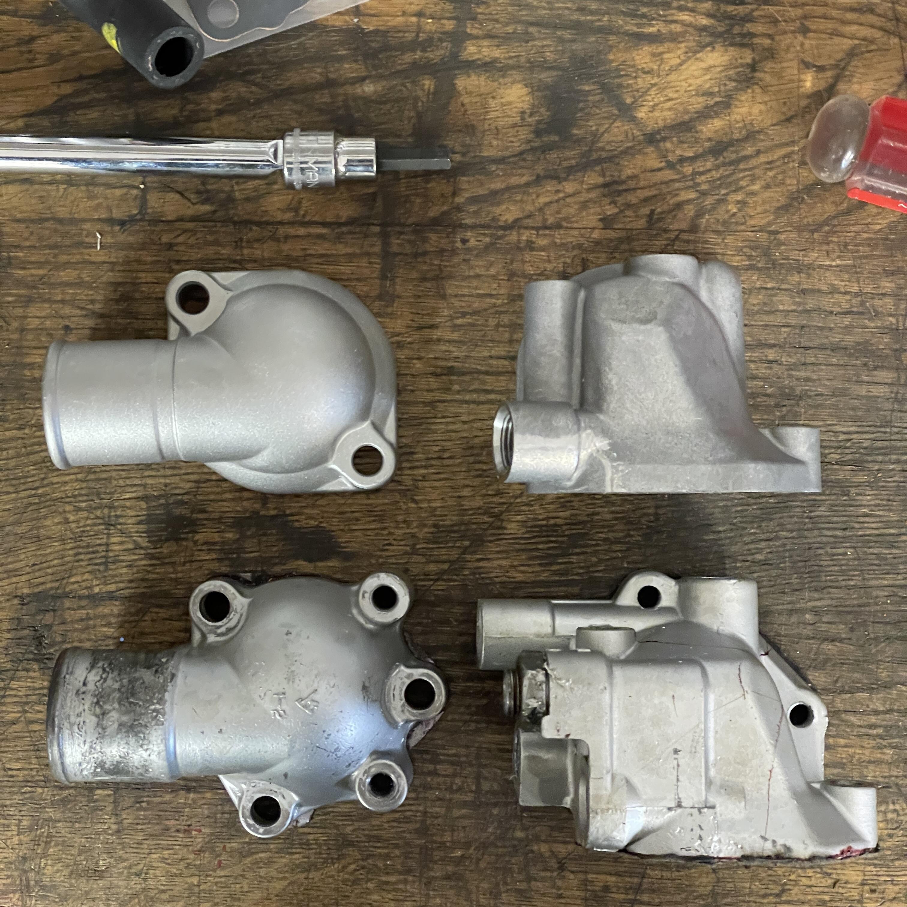
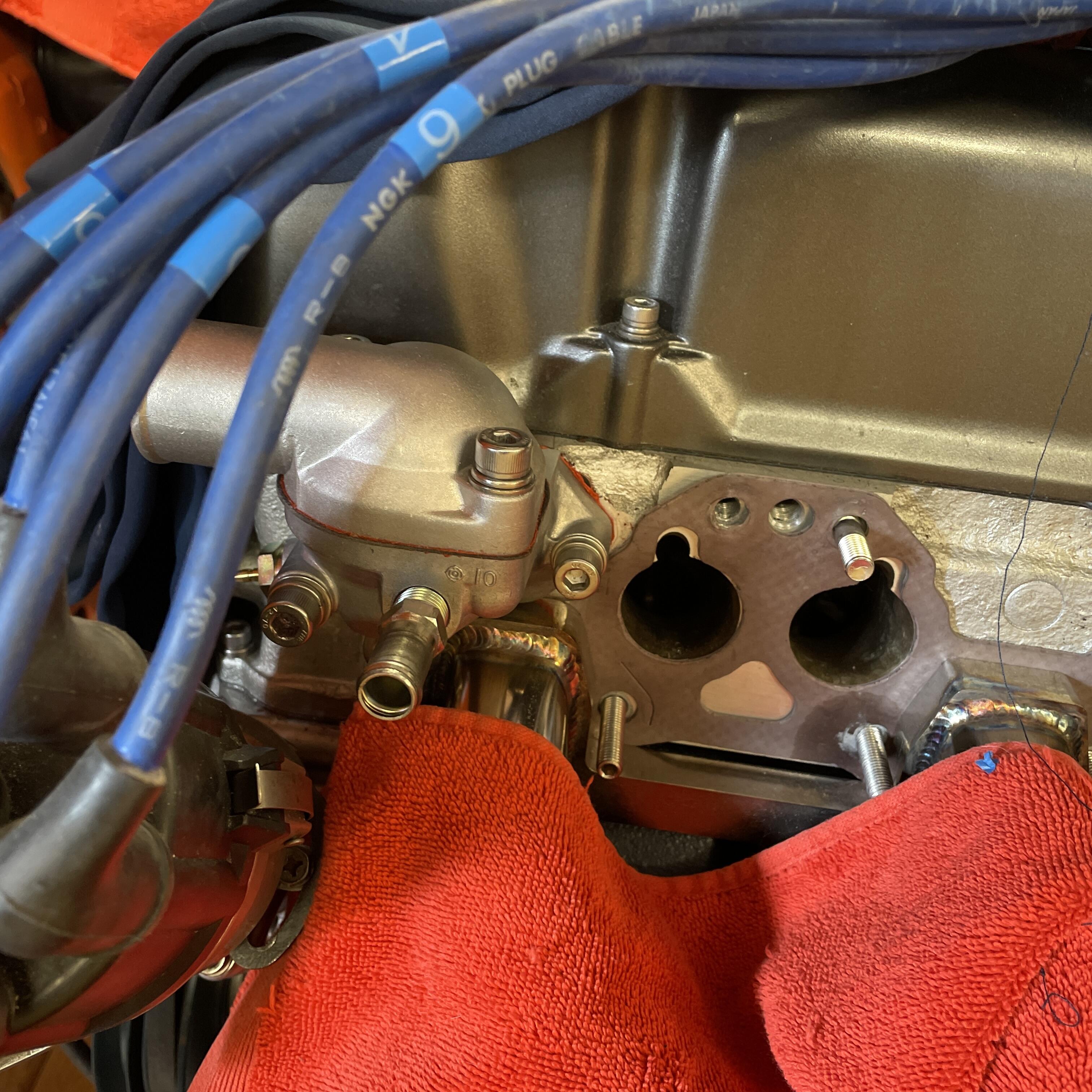
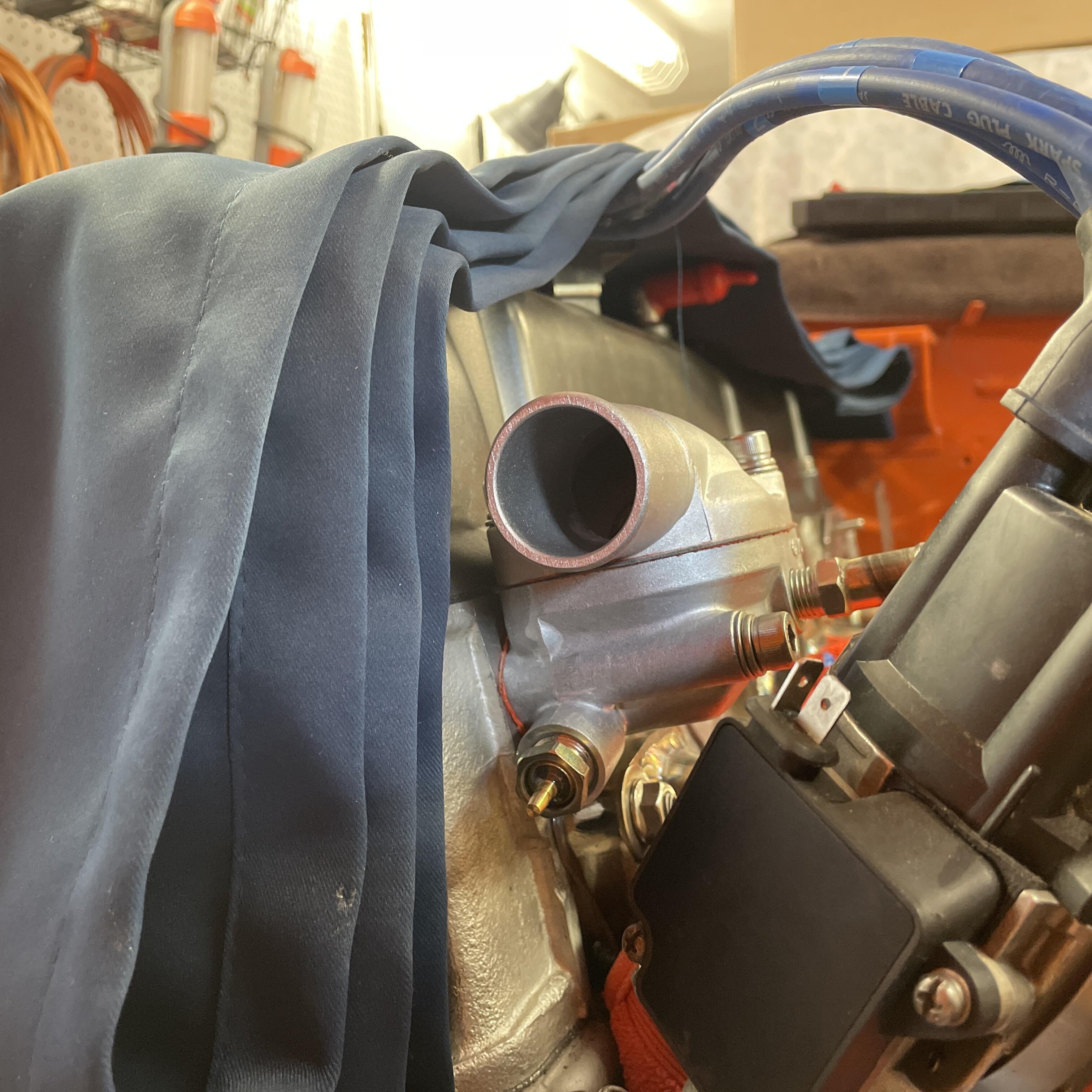
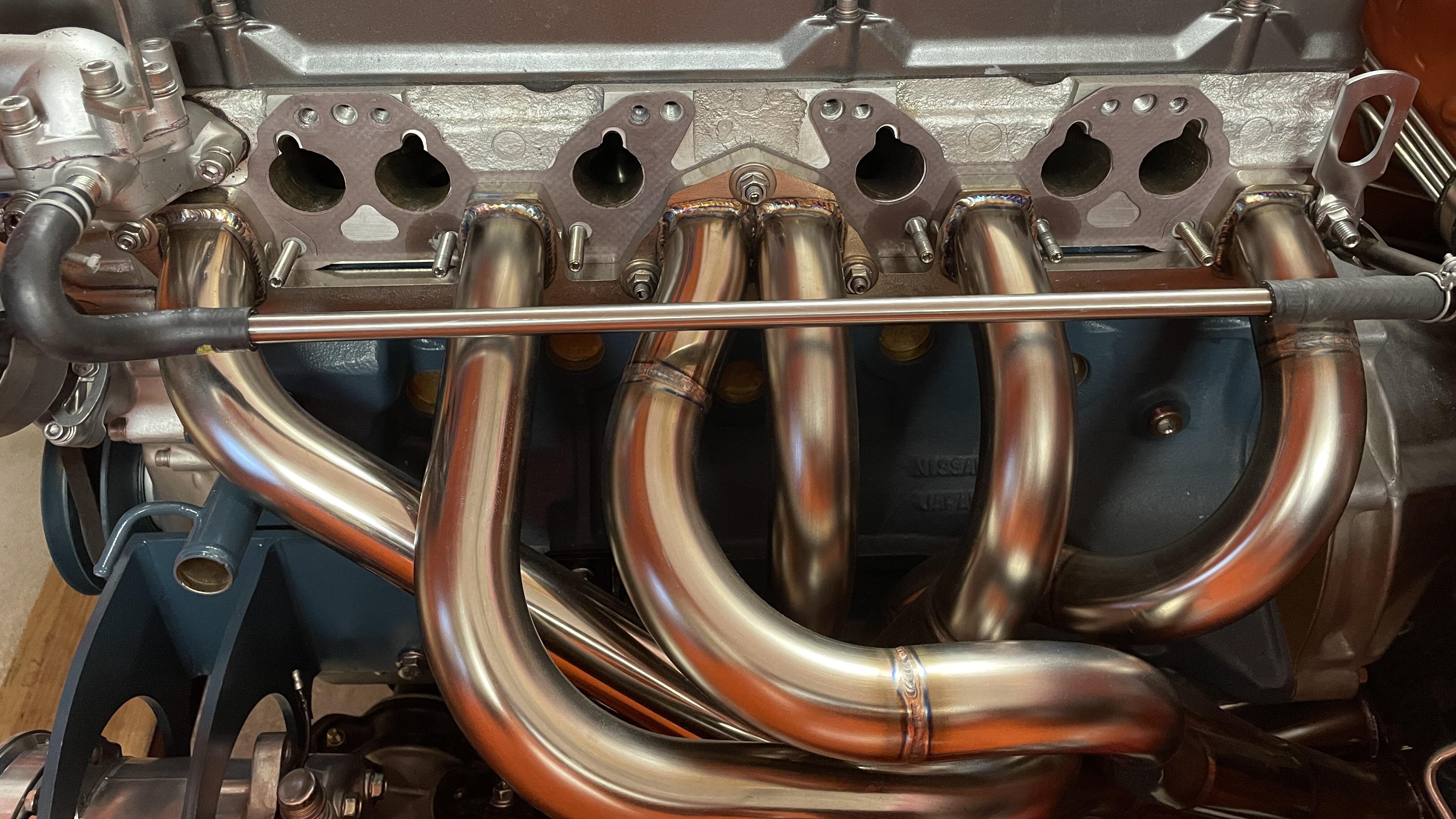
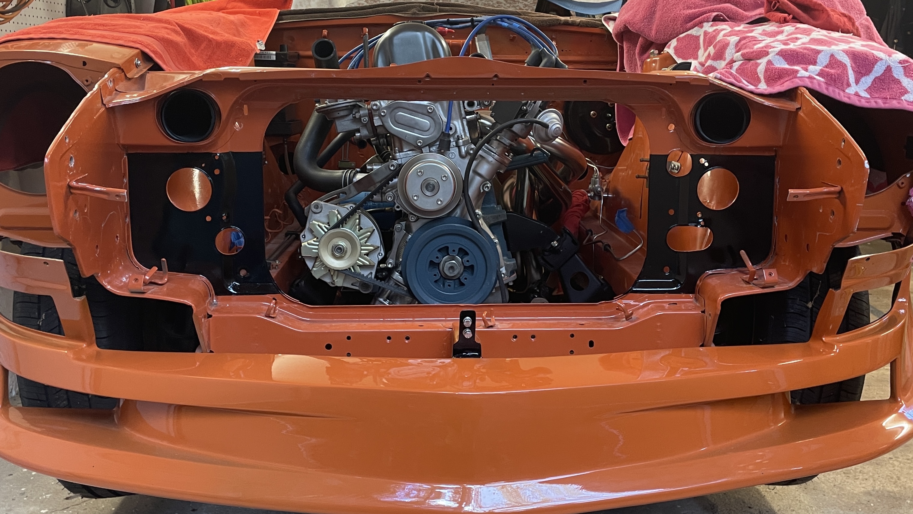
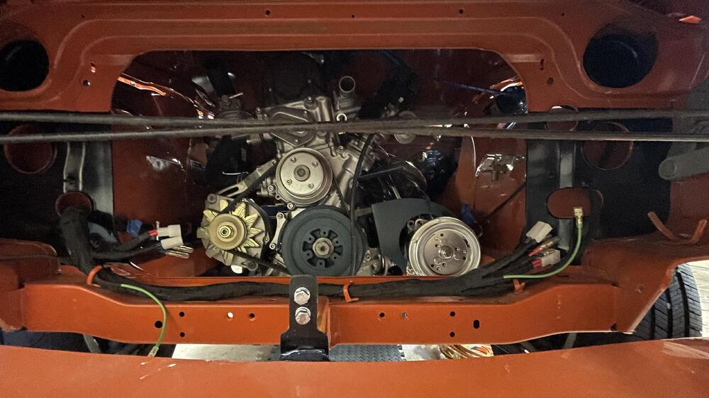
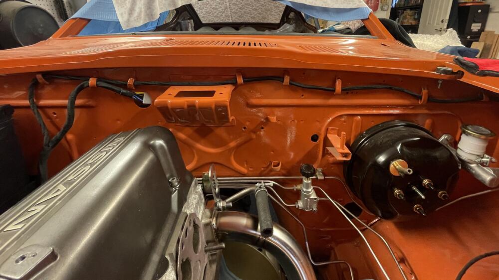
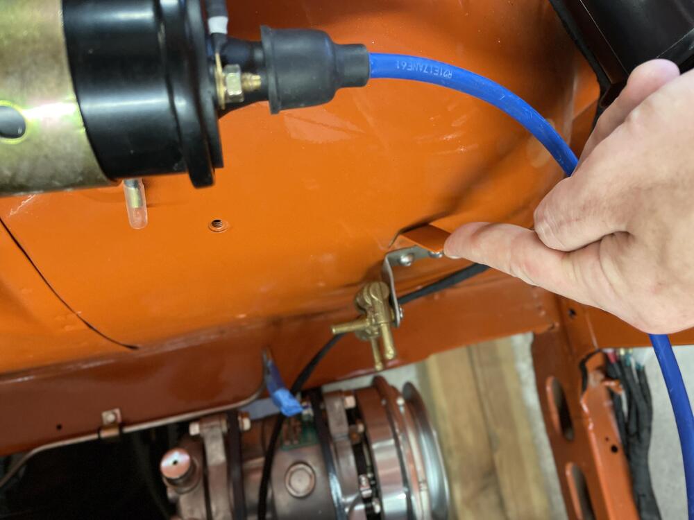
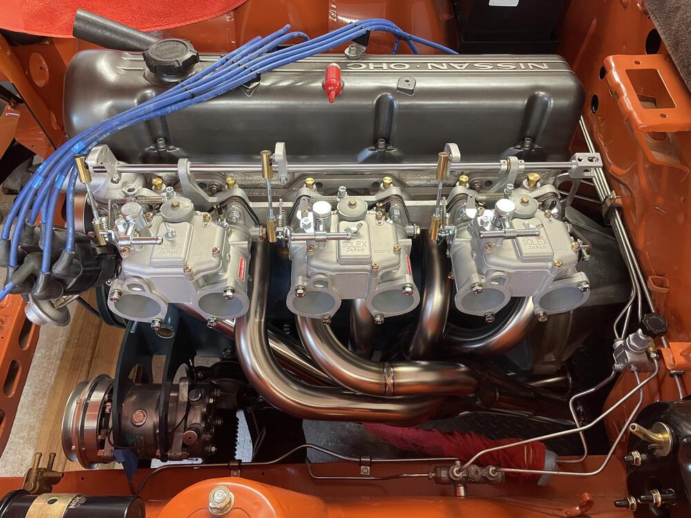
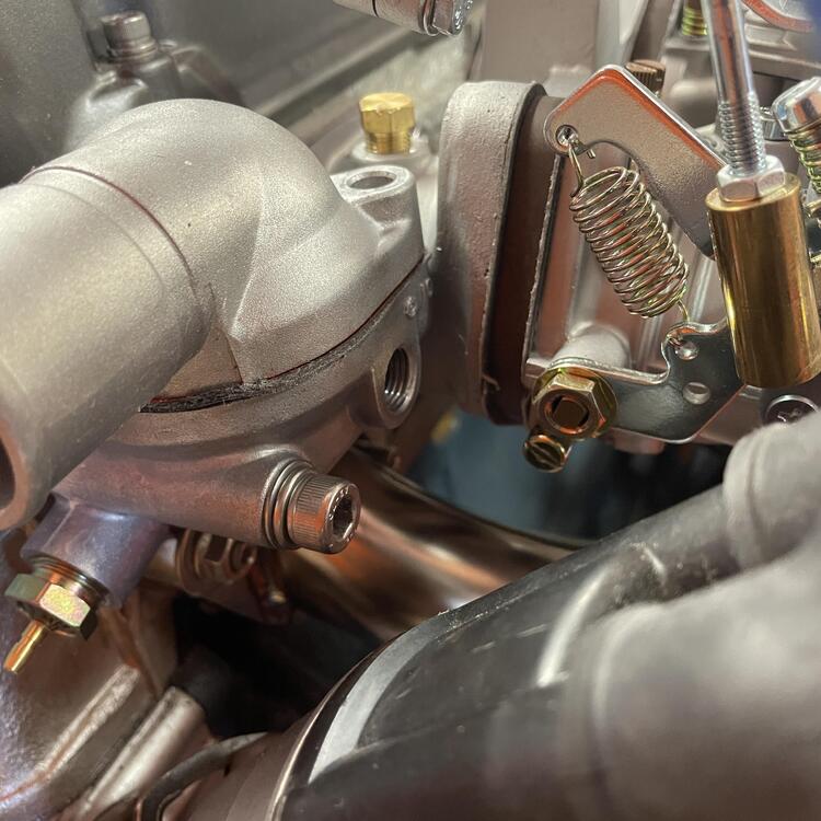
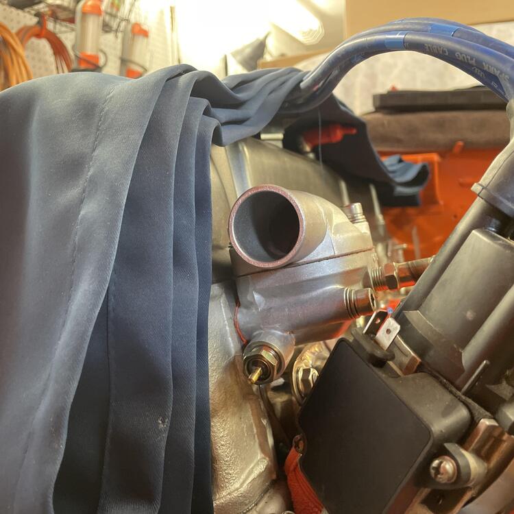
The engine harness is in. Everything is pretty much right. There are a few places where it got twisted as I was wrapping it, and the headlight plugs aren’t exactly in the right place, but I can mitigate that when I require the front lights. The harness is quite a bit thicker than OEM because I used marine wire, so I had to trim the firewall boot all the way to the widest hole size. As a result it’s not quite tight, so I need to fix that, but otherwise it’s done. ☝By the way, does anyone know what this tab is for? I assumed it’s for a clip to hold the coil wire because it’s similar to the tabs for the plug wire clips. *** I also test fit my Mikuni setup: Okay, so… It wouldn’t be my car without some substantial but not insurmountable problems. They are almost entirely because I went with the Mikuni manifold, which has the shortest runners of all of the options. The Harada I traded for this one probably wouldn’t have had any of them. There is interference between the manifold/carbs and a few of the factory configurations: 1. The water pipe that goes into the thermostat hits the throttle linkage. Yes, the one I just made that stainless steel pipe for. I’m going to see what a 45° or 90° elbow adapter does to fix it. 2. The OEM manifold studs are too long by around 3mm and the stainless ones by about 11mm. Luckily I was able to figure out that the stainless “manifold studs” that you see all over are actually set screws, and you can get them in any length (in 5mm increments) at McMaster Carr. I have 40 and 45mm studs/set screws on the way (watch, I’ll end up needing 35mm). 3. The metal riser for the plug wire clip hits the manifold. It definitely has to come off to get the manifold on, but I think this one is for a ZX. The 240z one at Z Car Depot is different and may work. 4. The plug wires bind up in the throttle linkage. I think I can partially fix this by adjusting the linkage so it isn’t sticking straight up, but I may end up rerouting them. *** Lastly, I replaced my corroded and beat up 280ZX thermostat housing with a new one for a 240z. It didn’t fix any of the interference issues but it looks nice and I don’t have a bunch of plugged sensor holes.


-
No, I haven’t. This is straight out of the box.
-
Nope. Spirit Garage https://www.spiritgarage.com/
-
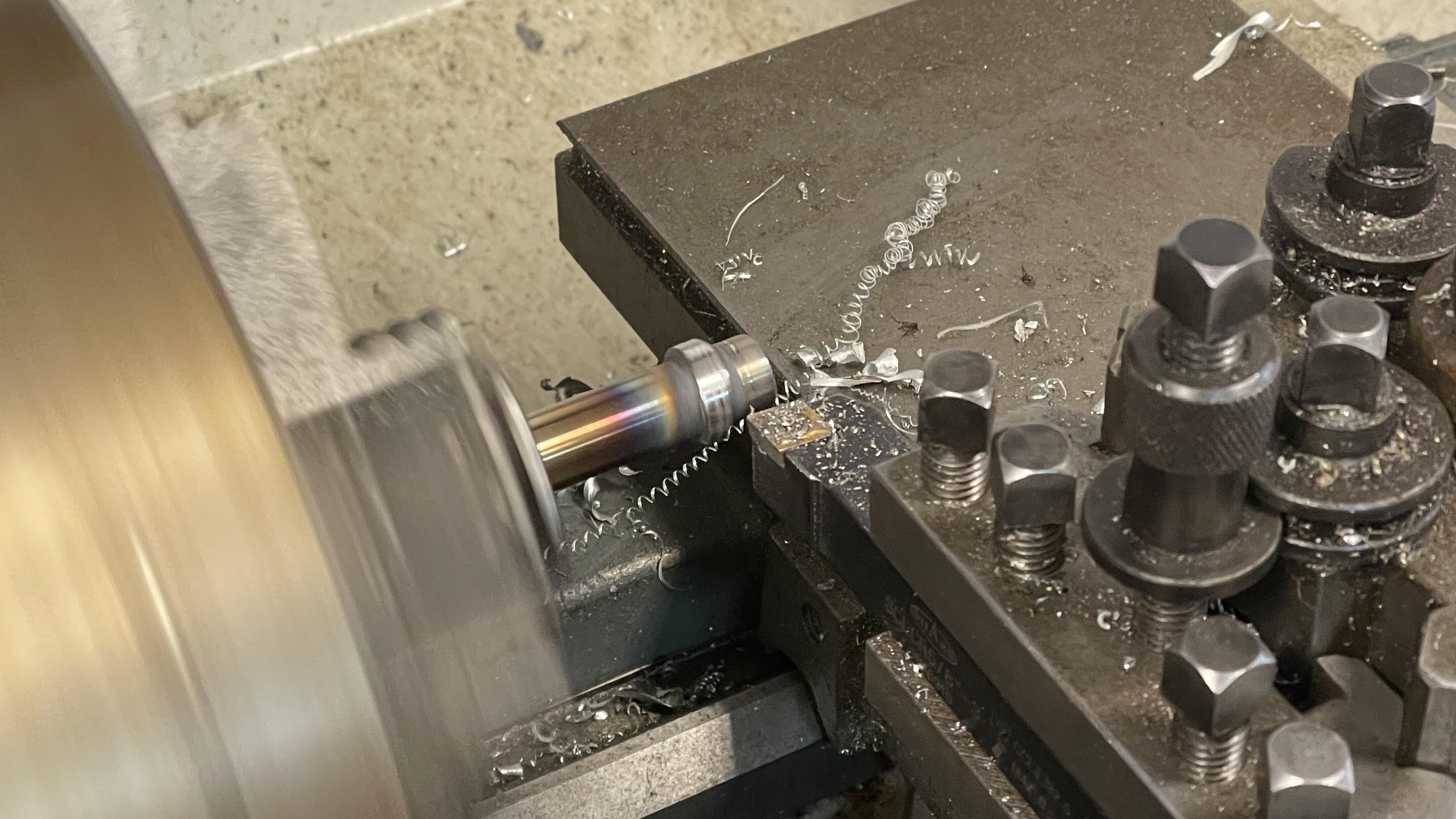
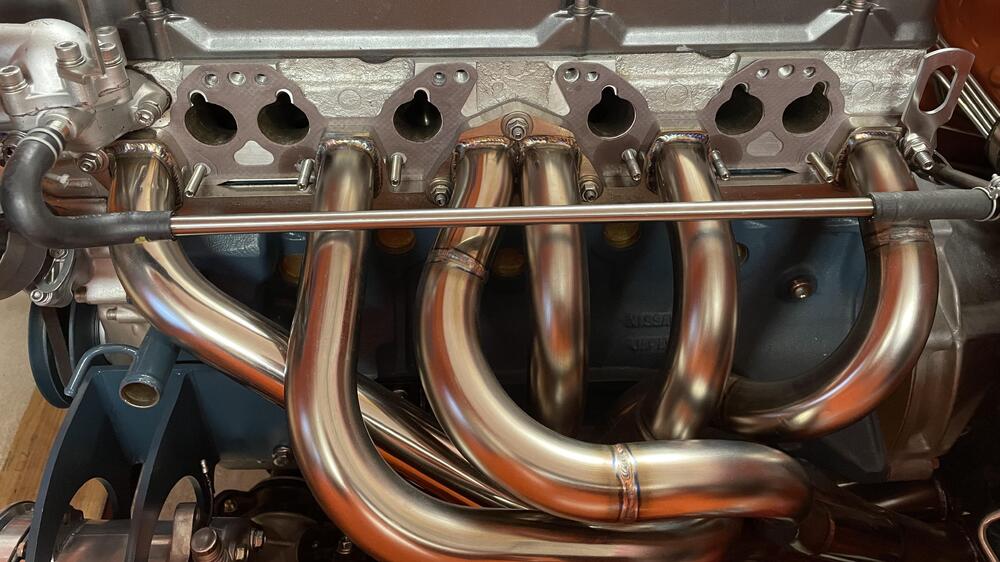
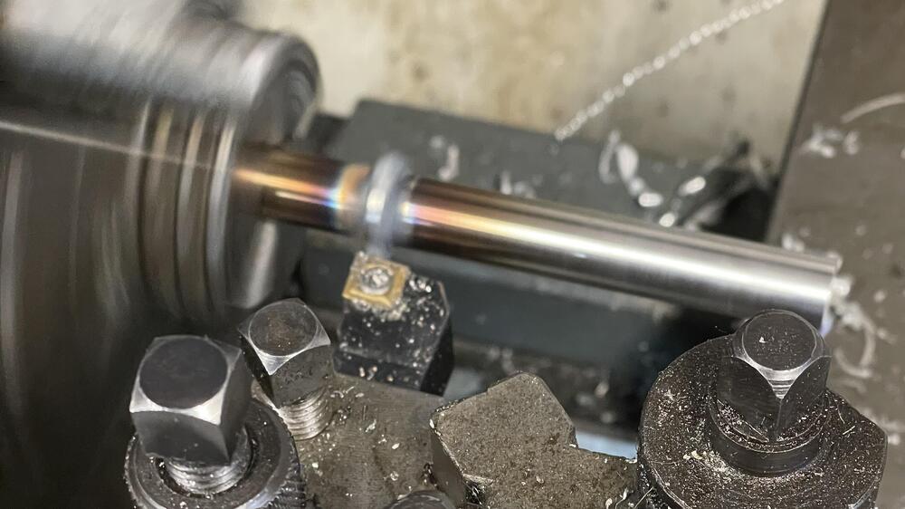
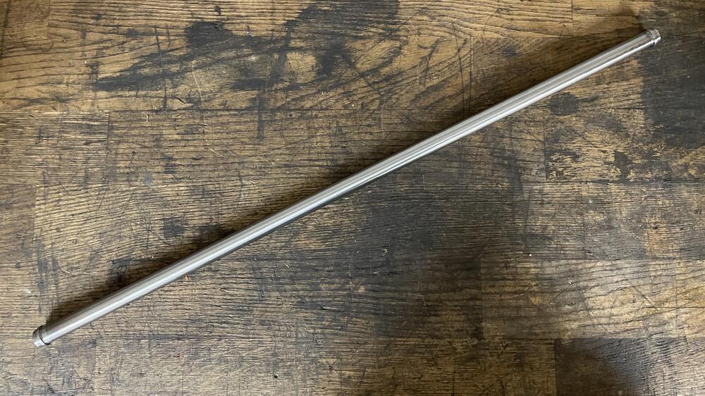
I made a manifold bypass tube out of stainless today so I could reconnect the coolant bypass tube in the rear of the engine to the thermostat housing. I received a great deal of snark on the FB Mikuni group when I asked how others were completing this part of the coolant circuit (short story is most of them don’t and sacrifice their heater) but I want everything working as designed and to be able to drive in the winter. Those that had done it just used “a rubber tube”, which is a wildly insufficient explanation, IMO. I opted for stainless because I am not confident a coolant tube poached from another car would survive the header heat. There’s a chance I will need to wrap this to keep the heat out and not boil the coolant, and I possibly need to get different set of tubes to get this pipe up further away from the headers, but I’ll see if this configuration will get it above the heat shield when I test fit that in a few days. We will see. It’s 316 stainless, 1/2” OD, .6 wall thickness, and 19.5” long. Here are some shots of how I cleaned up the tig-welded hose clamp beads with a lathe, and then the final piece.

-
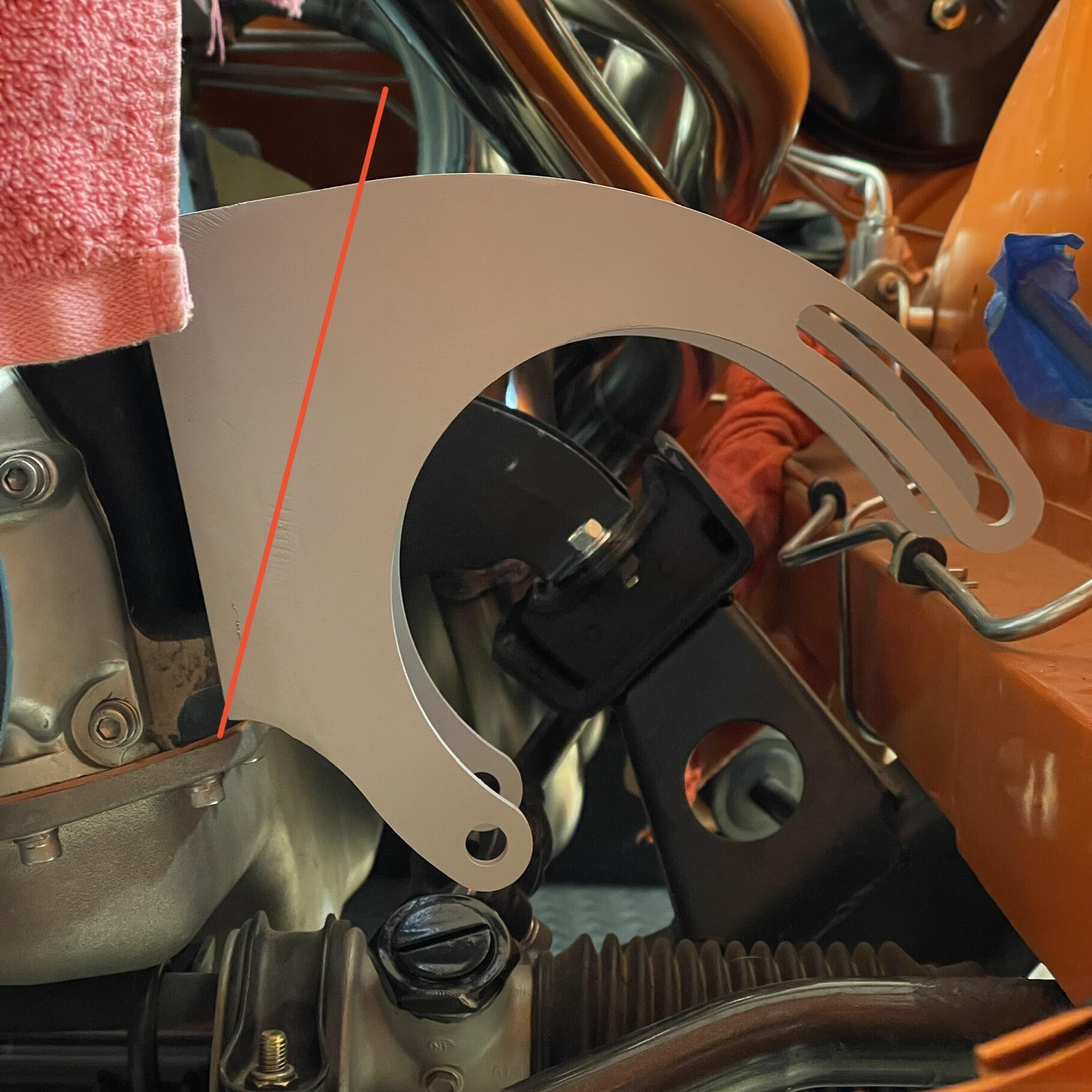
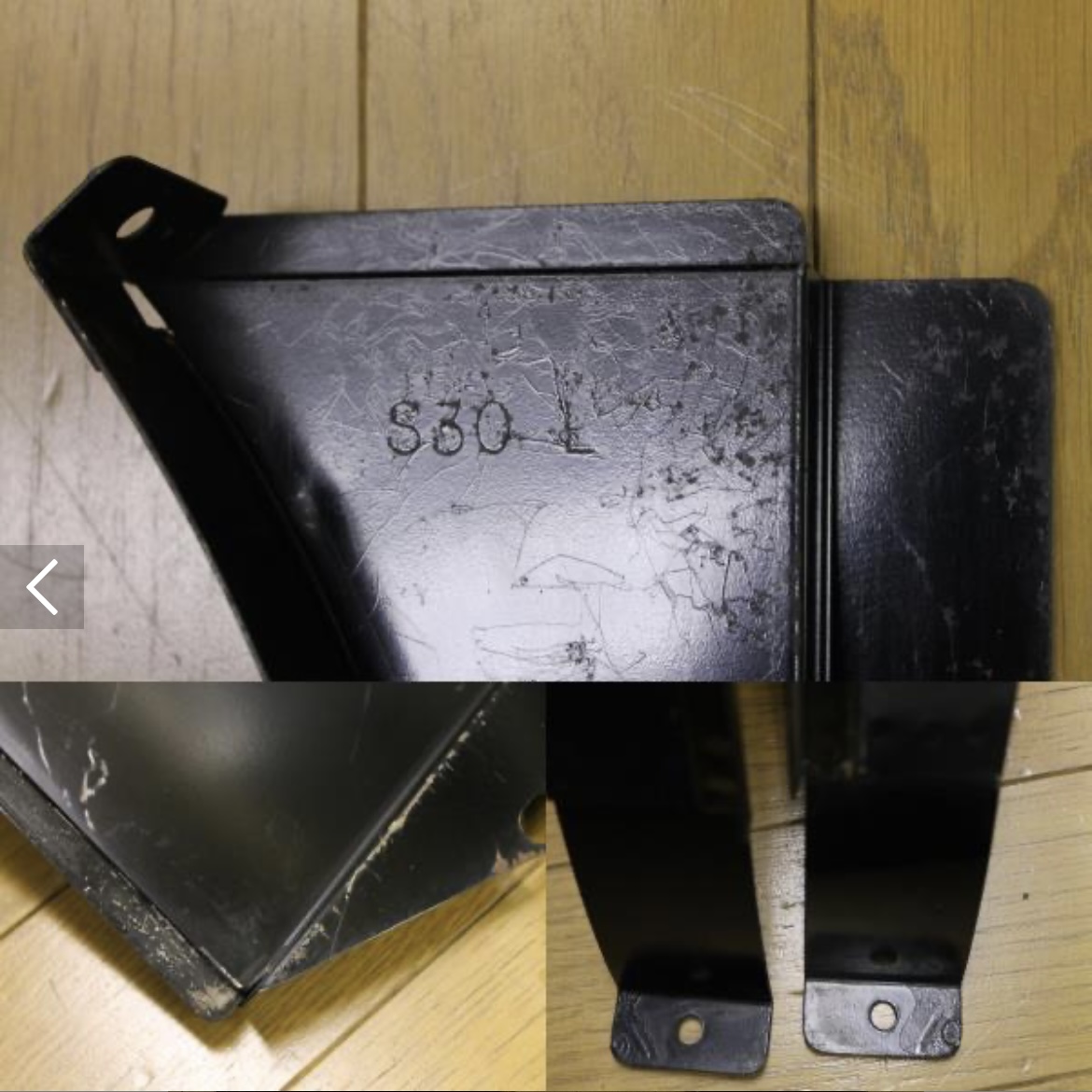
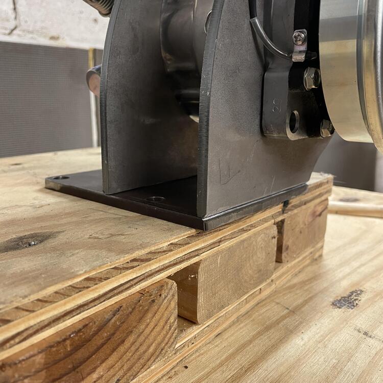
Yep. I would cut the brackets somewhere between where I cut it and where the red line is in the photo above. I considered doing this at the beginning and second guessed myself, thinking I needed the clearance for the air box. I may take the bracket off and cut them like this at some point down the road, but only after I’m done with the car.

-
I’ve been trying to figure out an elegant solution to connecting the coolant bypass tube to the thermostat water connector, and while I have some ideas, I thought I would ask to see how other people have done this. Right now I’m thinking I might be able to find a molded coolant line that has the right question mark shape for the front to connect to the thermostat, but then has a long straight segment that can go straight into the bypass tube in the back. Ideally it would be some Nissan OEM thing so it has the braided look that the other hoses on my engine have. I’ve also considered using fittings and braided tubing, but I’m not super into that idea. Another option is to run a long piece of stainless tubing between the factory hoses that are already there. That would function similarly to the tube that connects the two haves of the OEM manifold for the SUs, but I’m concerned about the heat from the headers boiling the coolant if I did that. Other considerations on my mind are… …hanging it from the carb heat shield to keep the hose from sagging and touching the headers …the material of the hose being melted by the headers, even if it stays up flush to the carbs …reducing the number of connections to the fewest possible (two) to prevent leaks or ruptures …OEM style looks Anyway, I would love to see how others have closed the look on the coolant system when they removed the SU manifold.
-
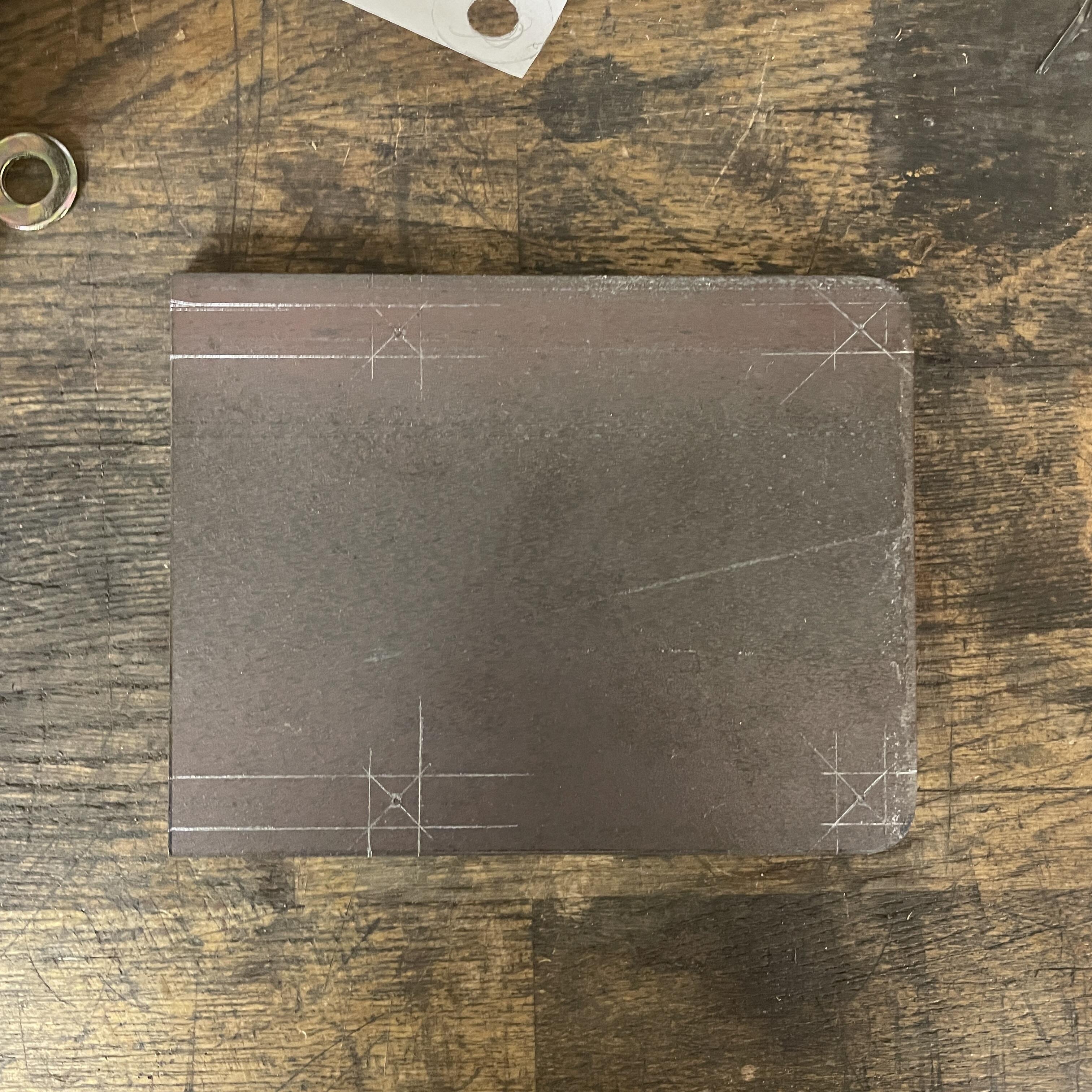
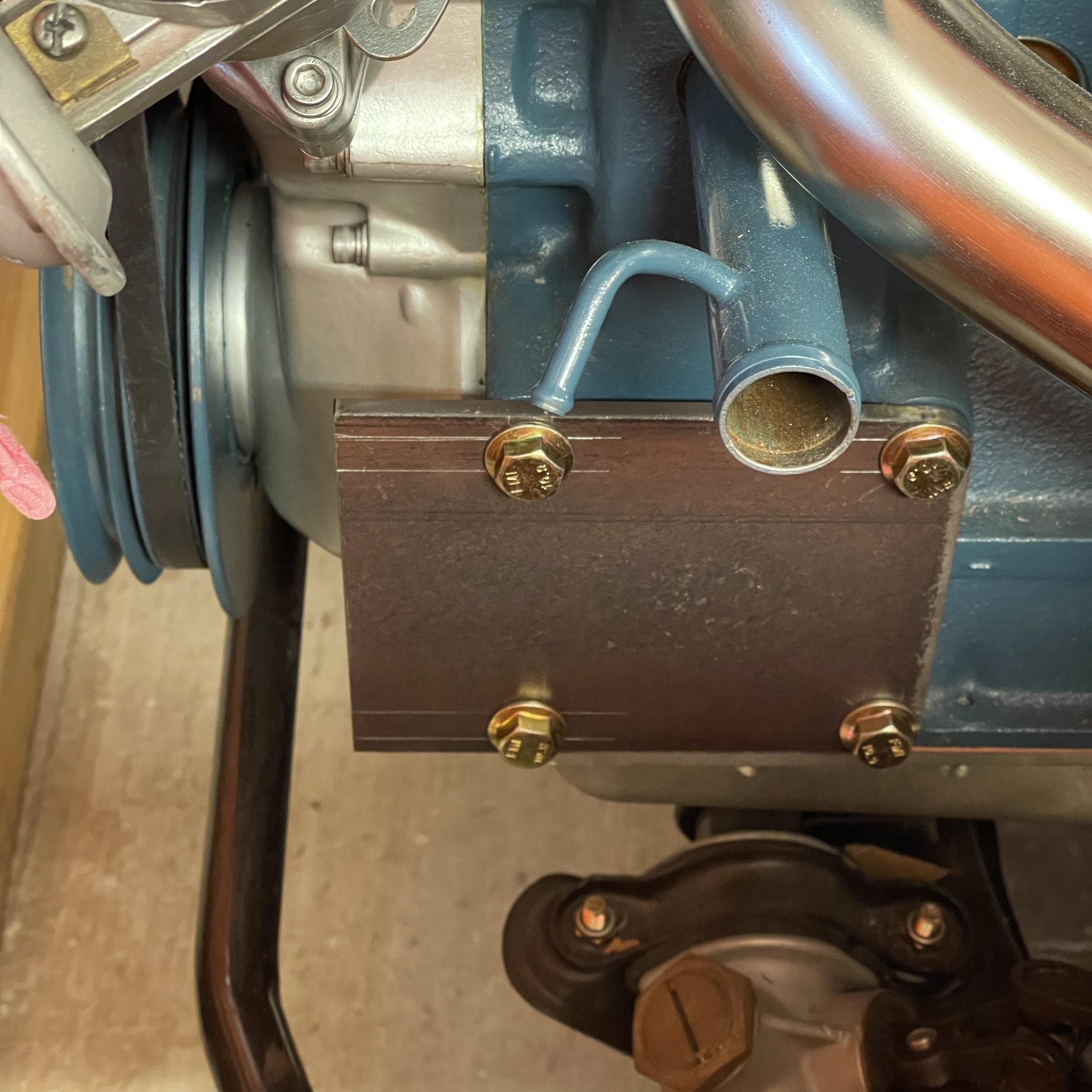
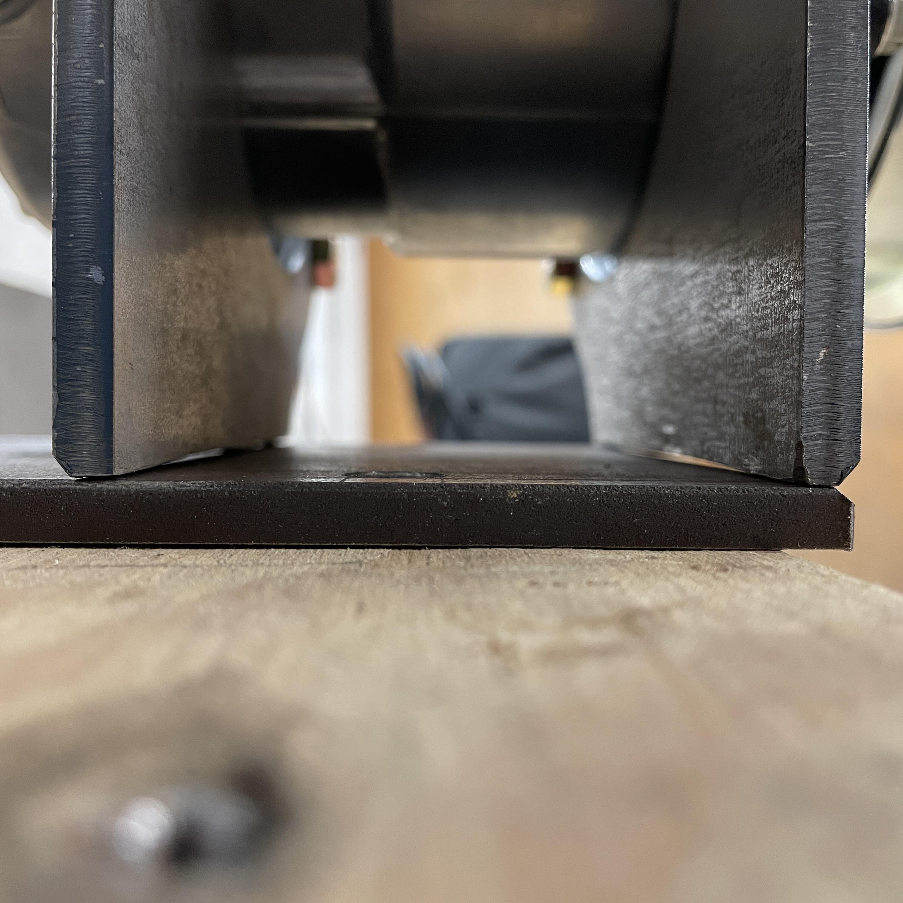
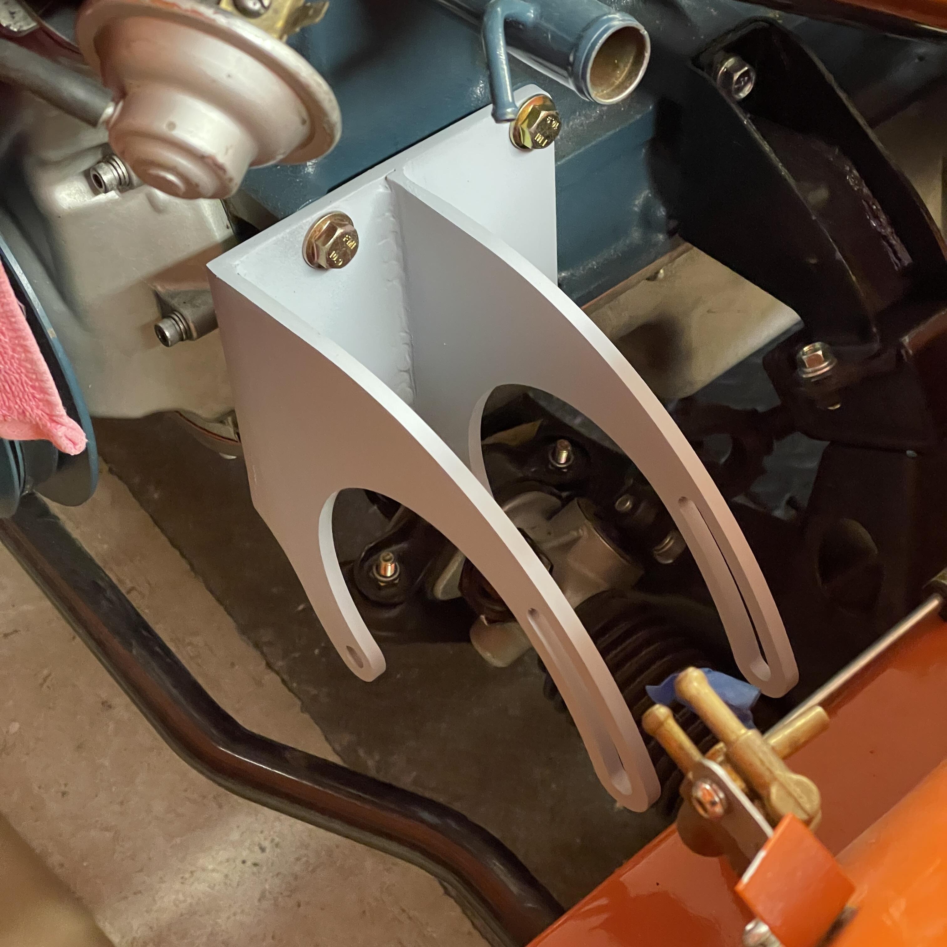
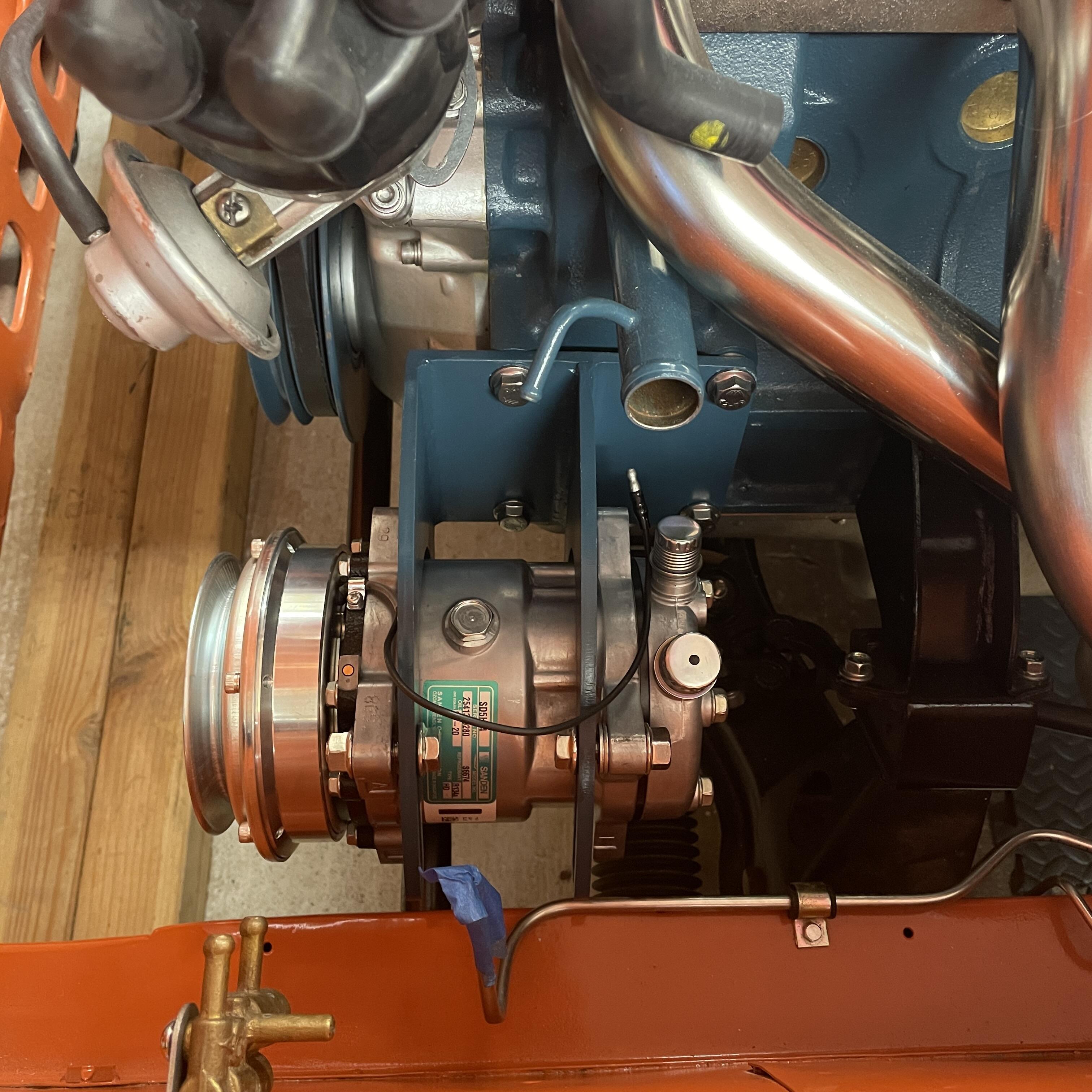
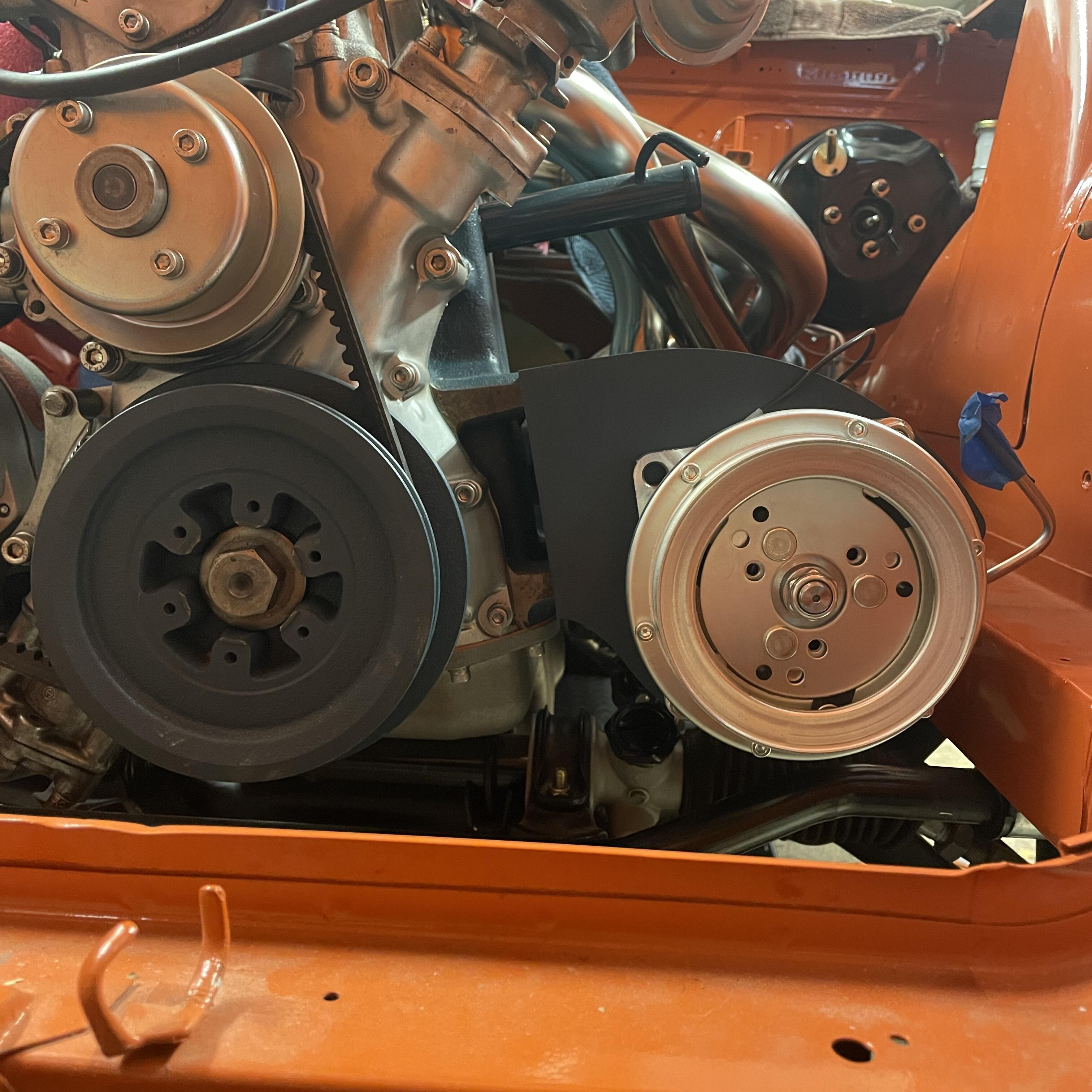
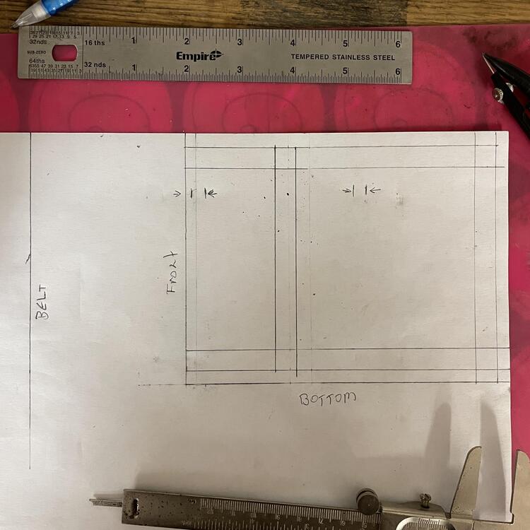
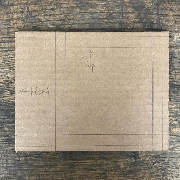
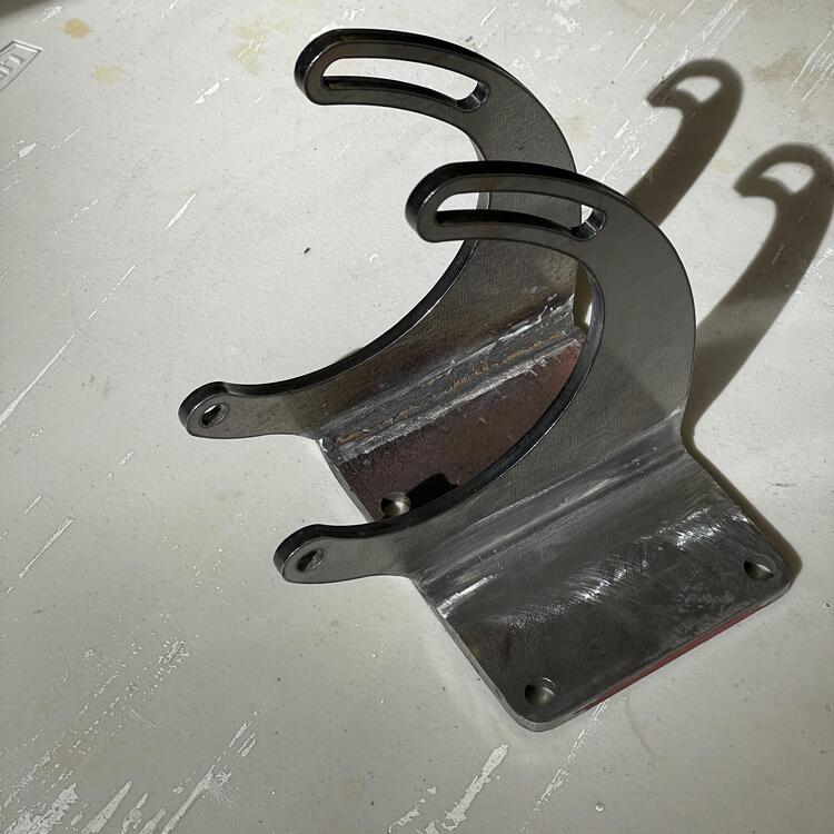
More progress… I fabbed up a bracket for my Sanden compressor because modifying the ZX bracket was turning out to be just too much. I used the Vintage Air universal bracket parts ($50 @ Summit) and a sheet of 1/4” steel from the hardware store, which I cut, drilled, and welded to the brackets. It came out okay. If I were going to do it over again (which I’m not) I would angle the bracket up more to 1. make more clearance for the compressor to slide in under the bracket, 2. move the compressor away from the frame when at the furthest point of adjustment, and 3. change the adjustment angle to be more perpendicular to the block, making the adjustment span more pronounce/longer. Otherwise I’m happy with it.


-
I’m good. I had ordered a harness boot from zcardepot that was labeled 1970-73, but I should have meassured the hole first. JDM Car Parts and MSA have the 280 boot, so I have one in the mail. Once I get that I can put this thing in, then on to fitting the body harness.
-
Yes. Good if you have parts to sell, bad if you want them. I slightly blame MZR and other customizers. There are only so many of the NLA parts that aren’t being reproduced, and I will bet they hoarded stocked up on them.
-
I blacked out the radiator bulkhead and grill tabs (thanks @Patcon for the thread showing how that’s done). Now I just need a 280z harness boot and I can put the engine harness in.


-
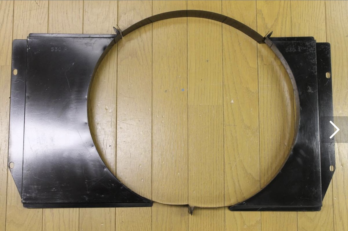
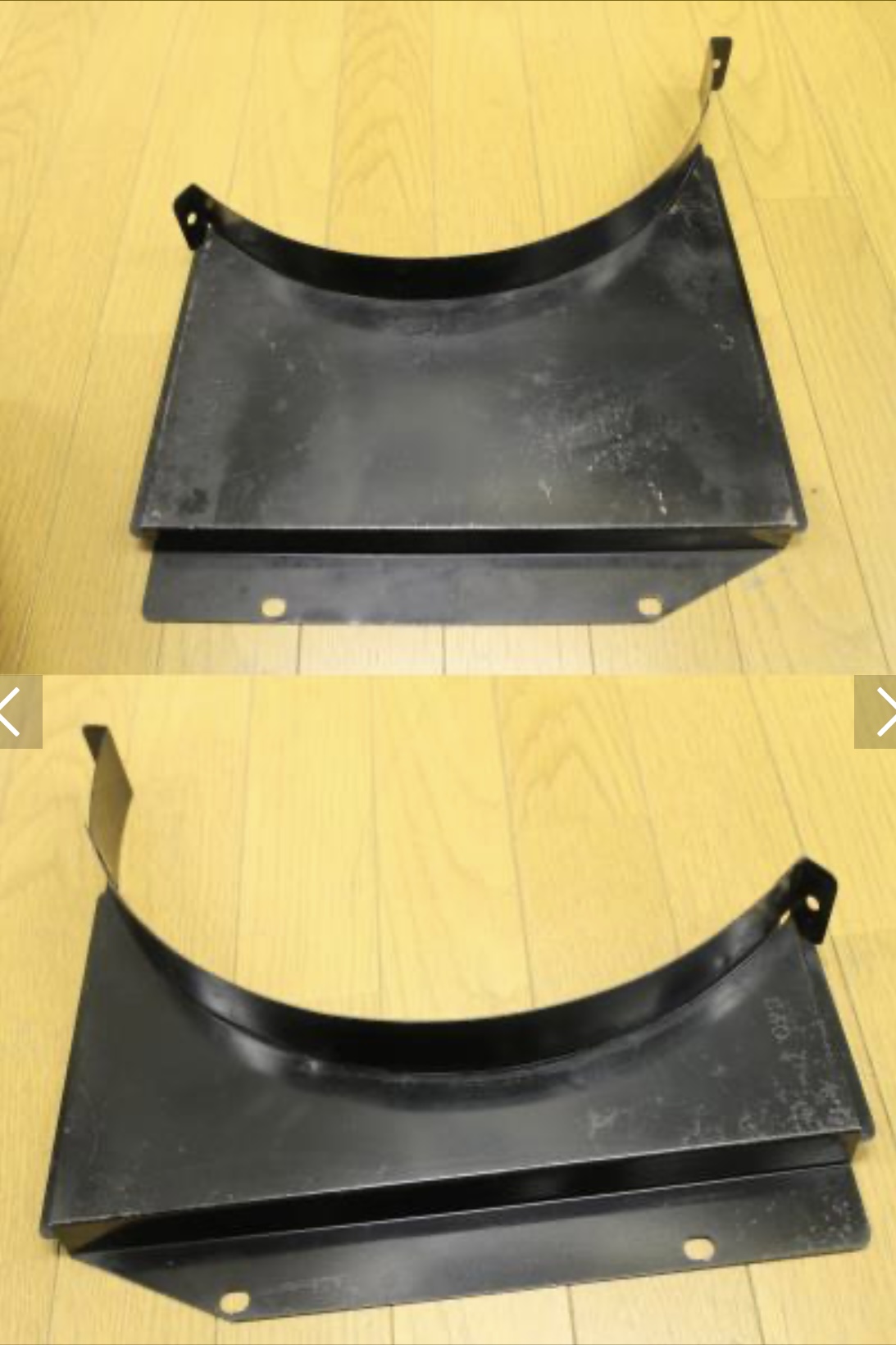
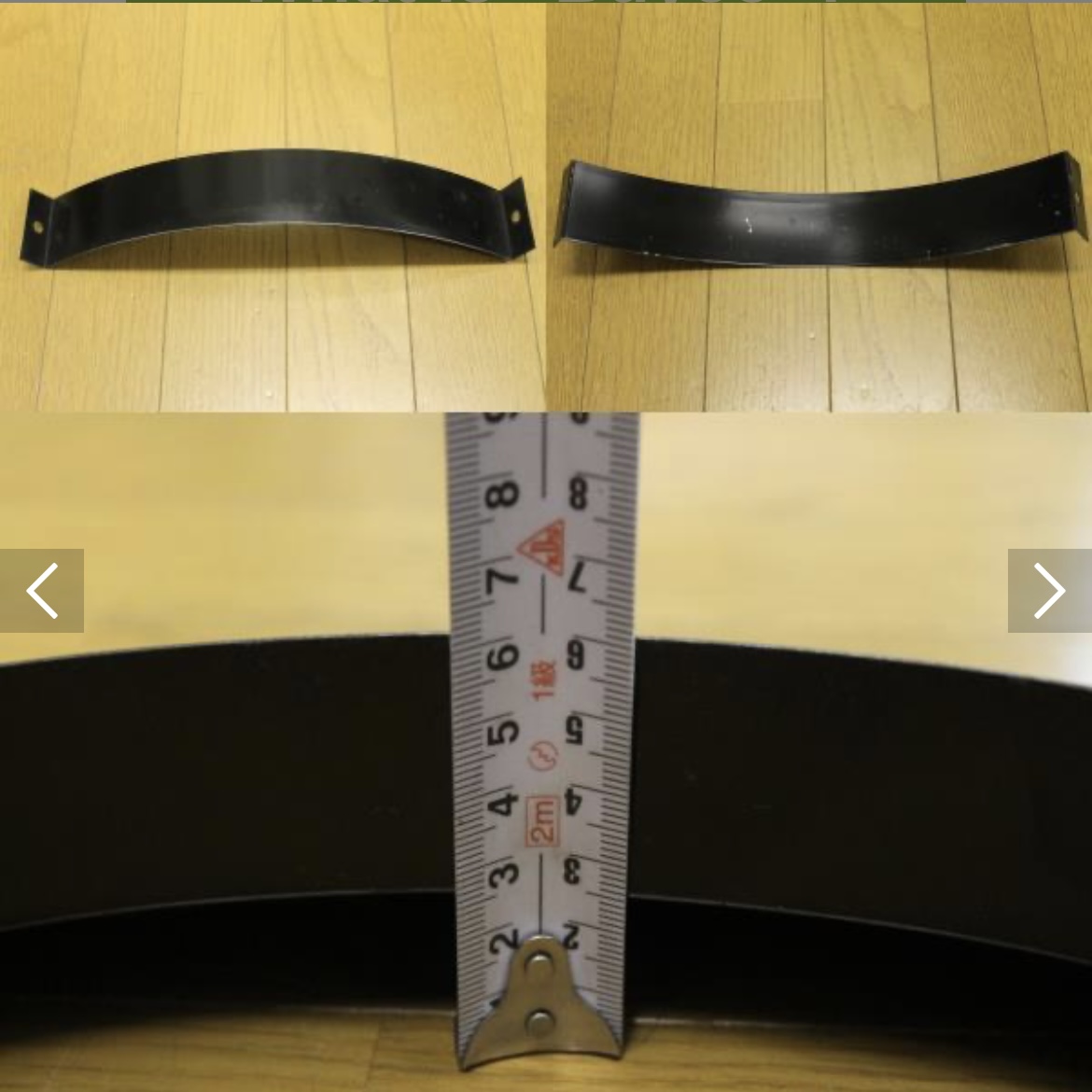
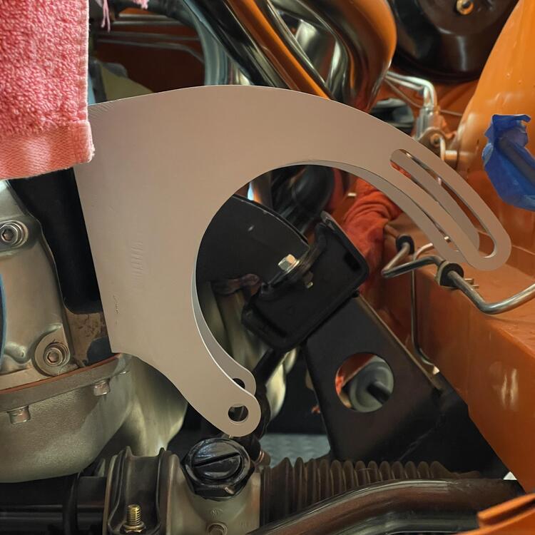
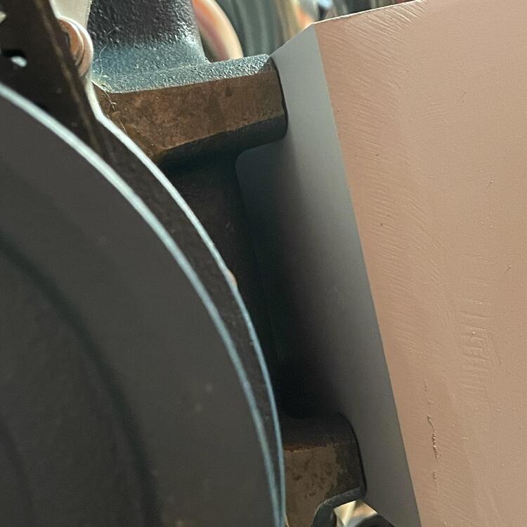
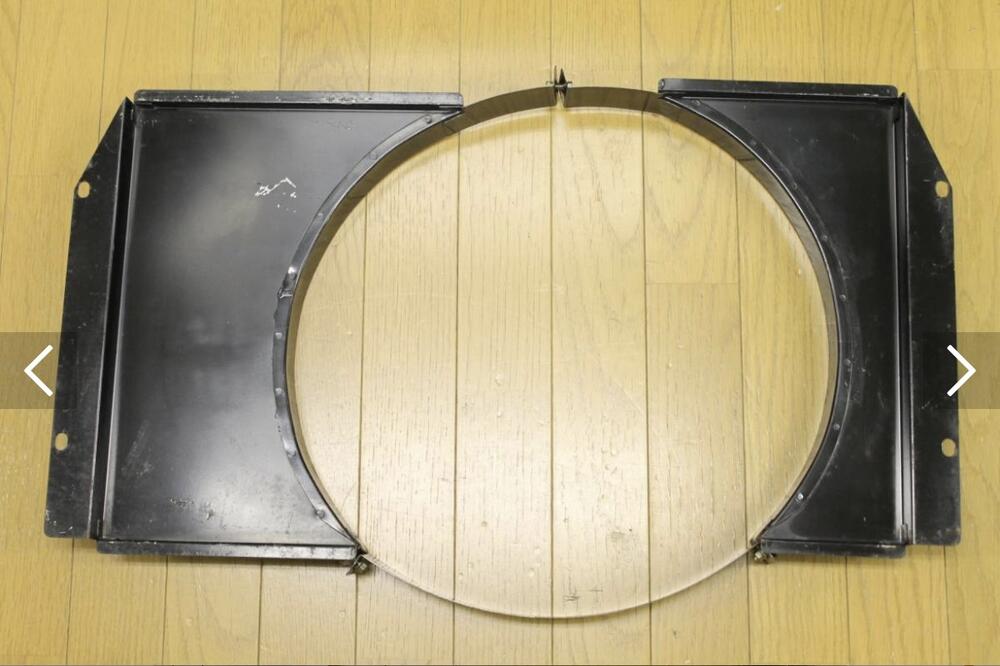
I’ll probably get the MSA one. This one is way too much. It’s also pretty different from the factory one. Other than being 3 pieces instead on one, it’s flat on the engine side. I was just curious if anyone had seen this before.
-
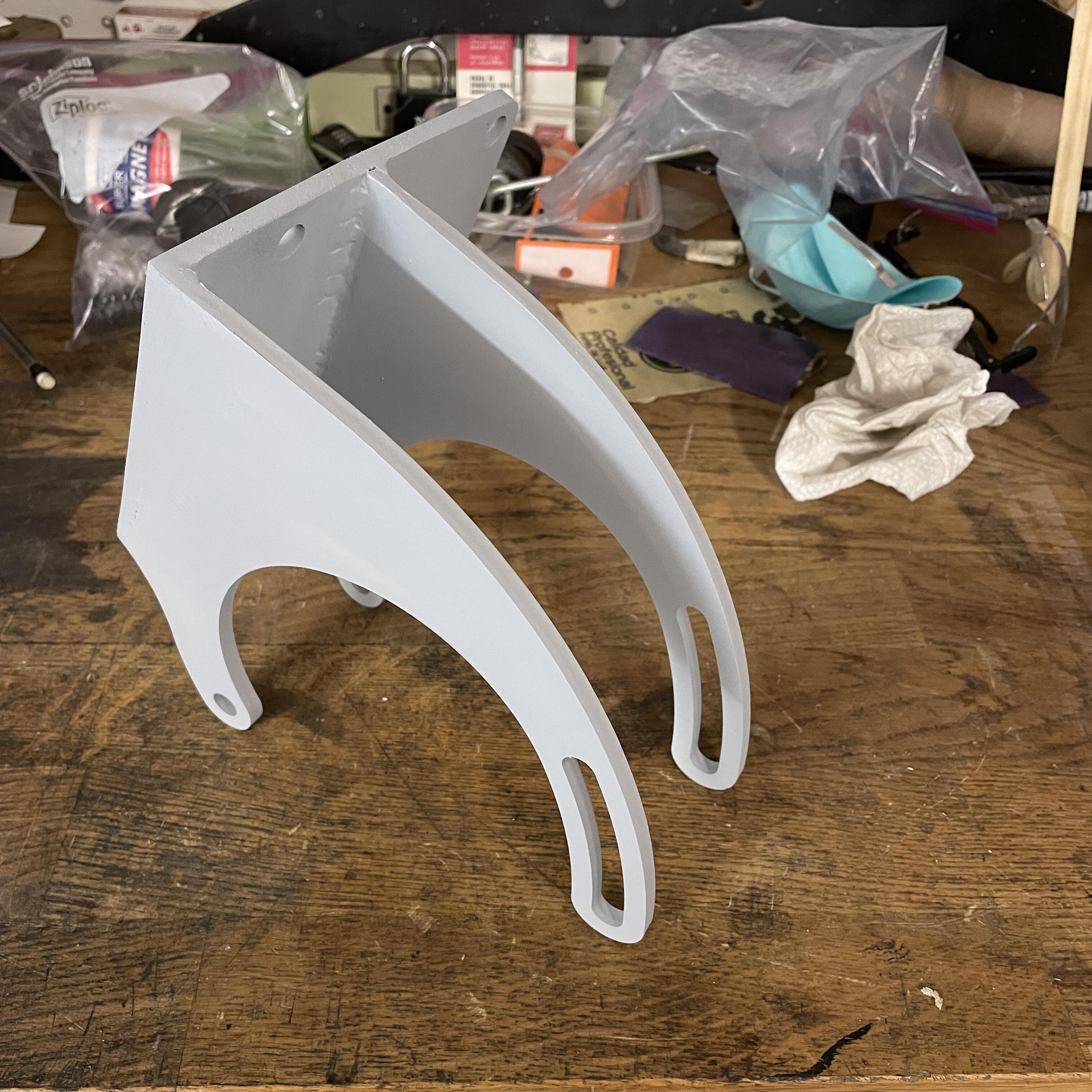
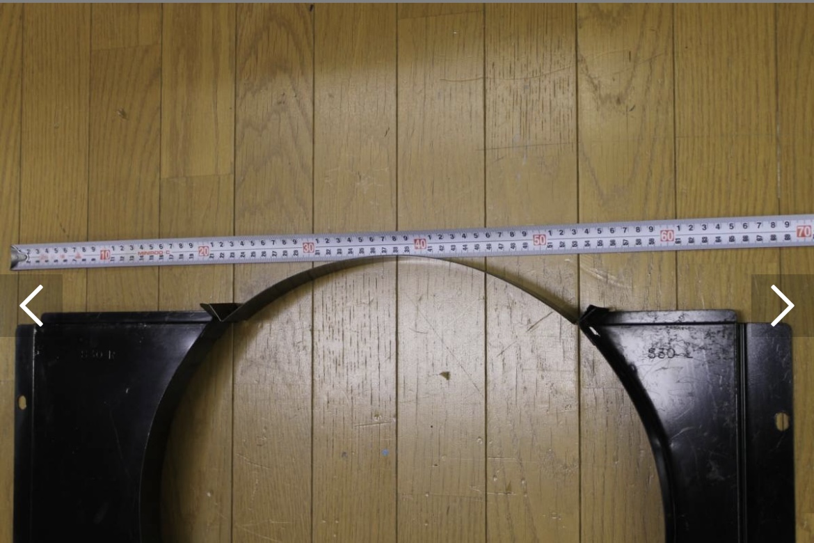
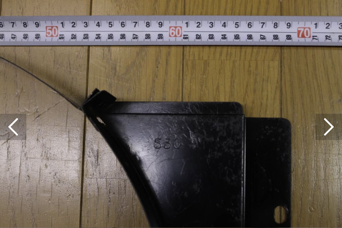
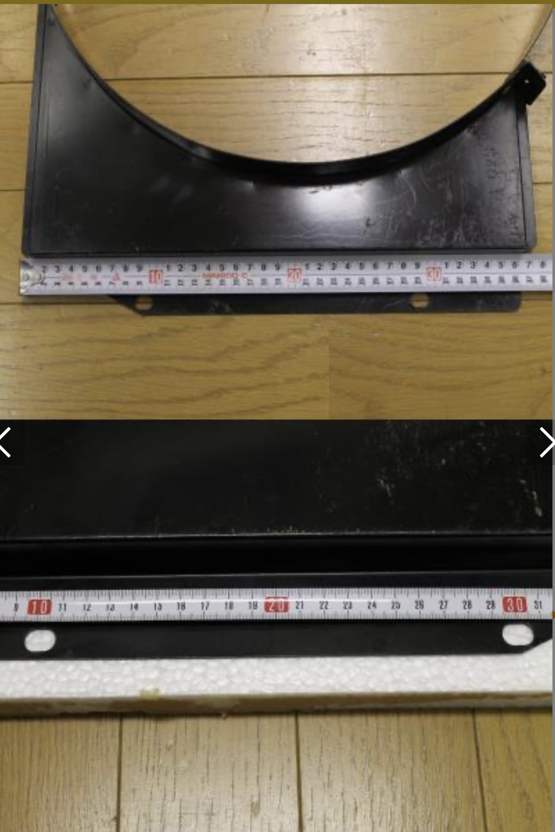
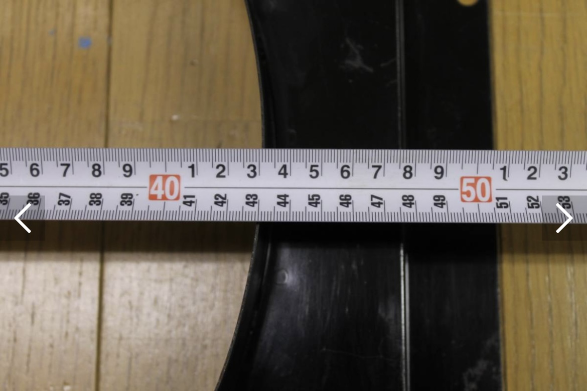
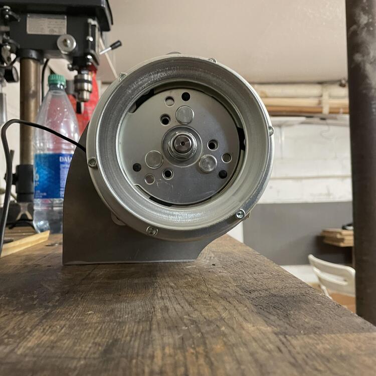
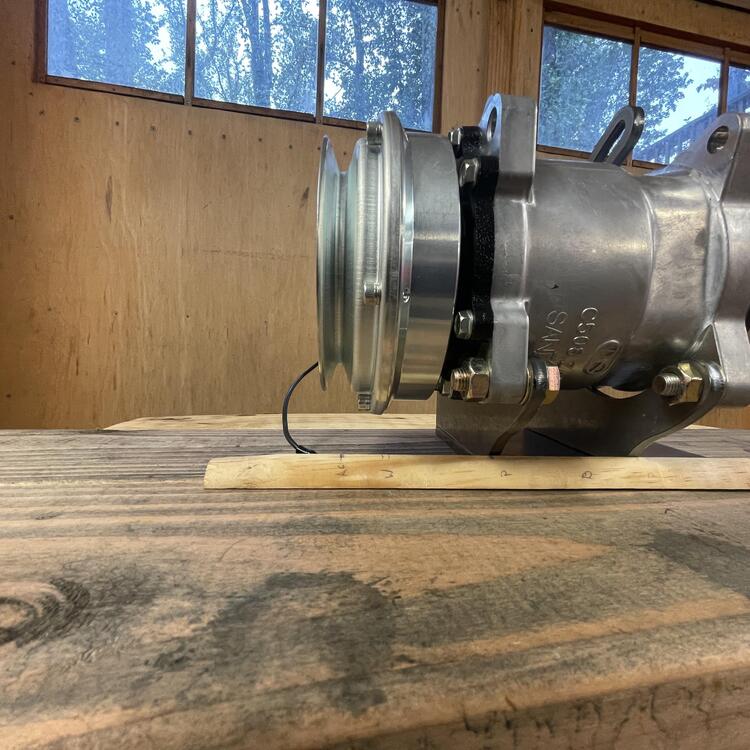
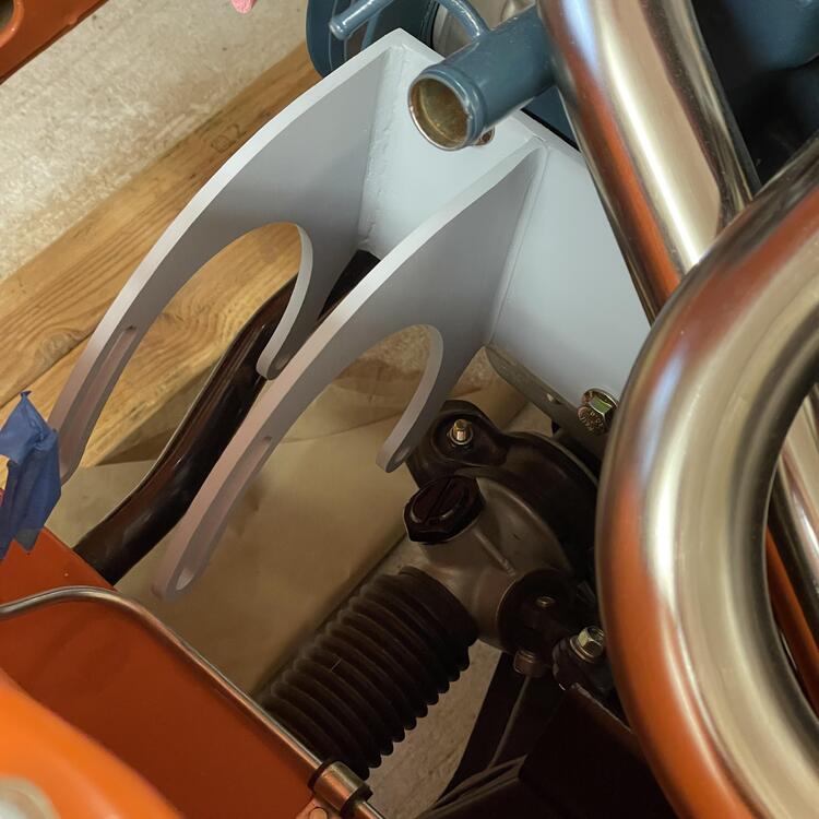
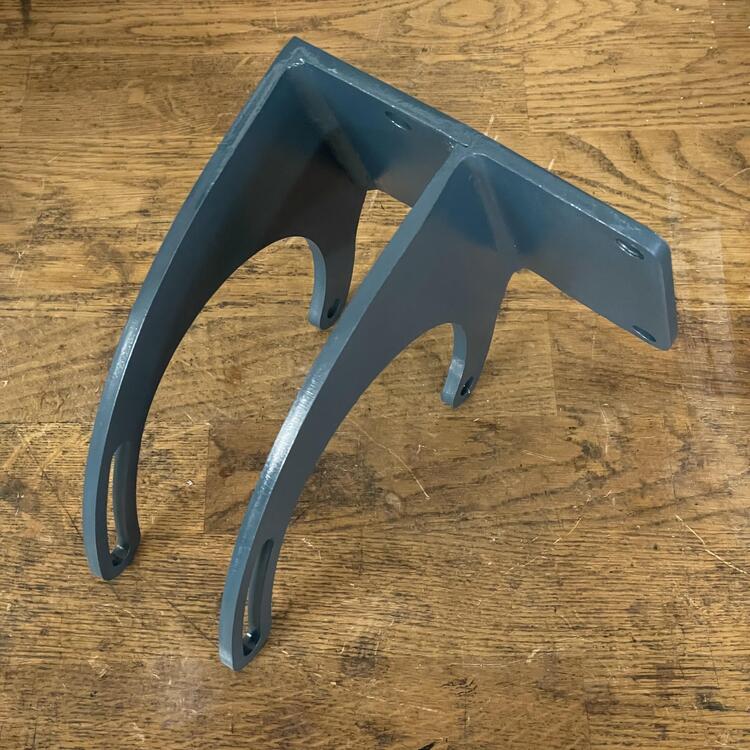
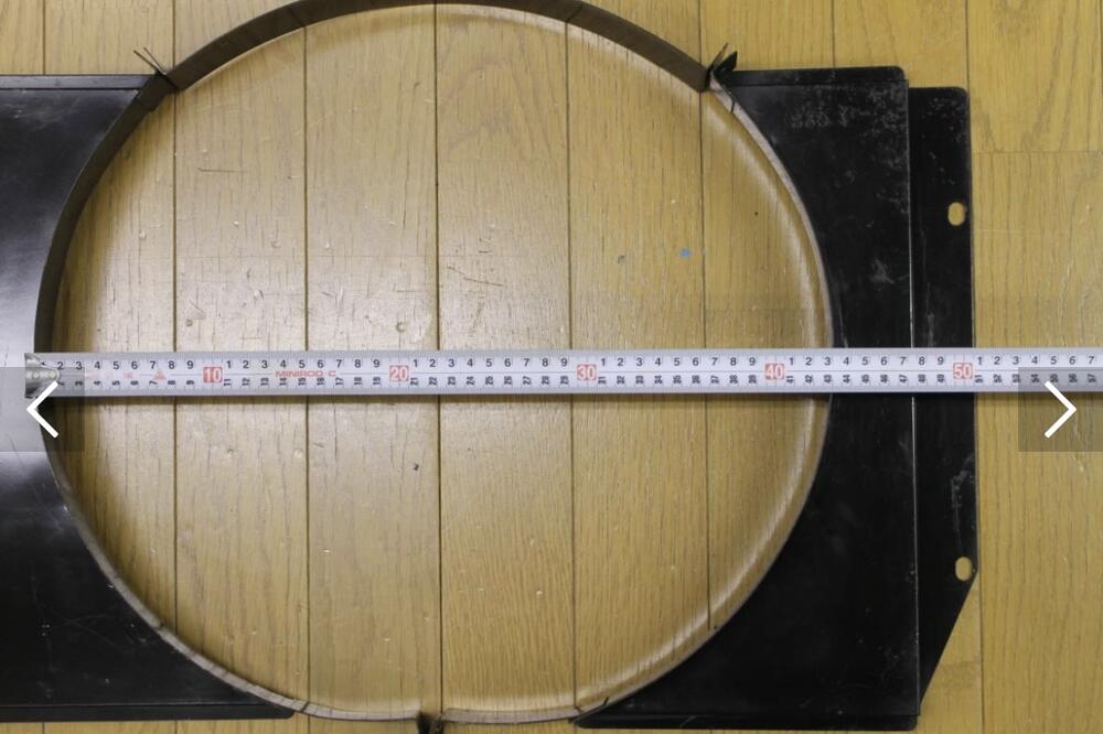
I stumbled upon what is said to be a fan shroud for a 240z (well, S30) made by Sanden. Has anyone ever seen one of these? Any thoughts on whether it is meant for the shorter 240 radiator or the taller 280 radiator?


-
View Advert Steel L6 to FS5W71B Gussets I am in search of the steel gussets that connect the F54 280ZX block to the bell housing on the FS5W71B five-speed transmission. Nissan part numbers are 30429-K1200 and 30430-K1200. The correct gussets will have four holes on the right side piece (see photos). They were also used in some limited L20 applications (i.e. 1980 720s; see illustration). Note that these are NOT the aluminum ones that are used on Z20/22/24 blocks (see photos). I have a source for NOS ones in Japan, so please keep your prices reasonable. Advertiser Matthew Abate Date 09/13/2023 Price Category Parts Wanted Year 1980 Model 280ZX, 720
-
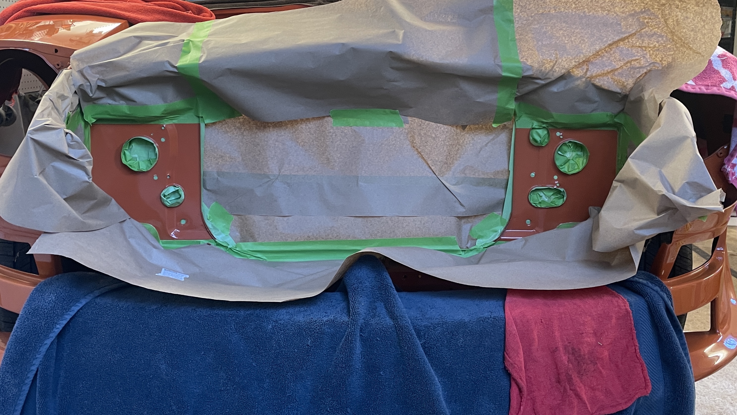
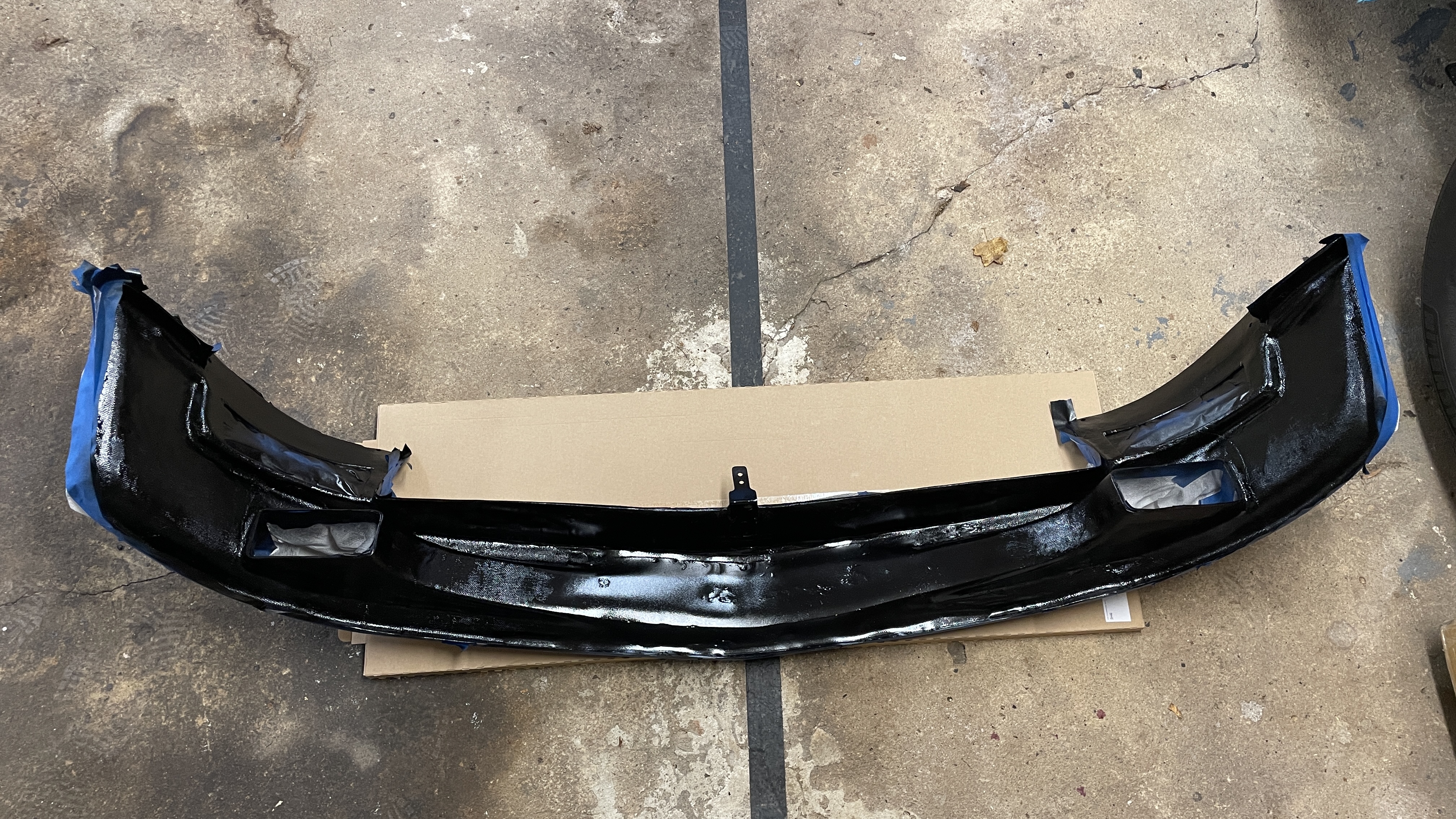
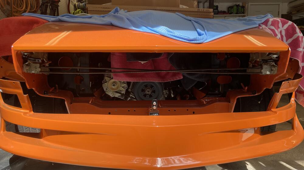
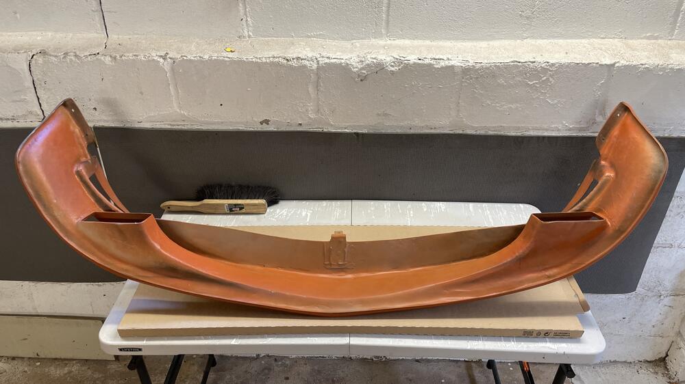
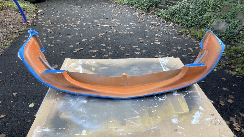
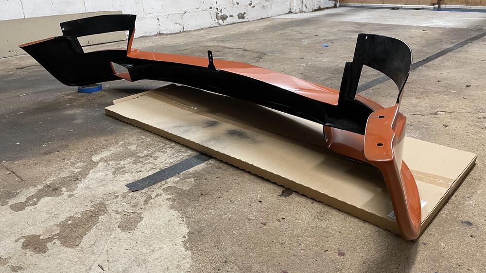
One of the many, many things the painter screwed up on my car was not painting the back of the air dam black like I asked him to. Not the most egregious screwup by far, but still annoying when compounded with everything else. I hit this with gloss black and it helps. Doesn’t fix the spots where the primer is showing through the orange but it’s better.

-
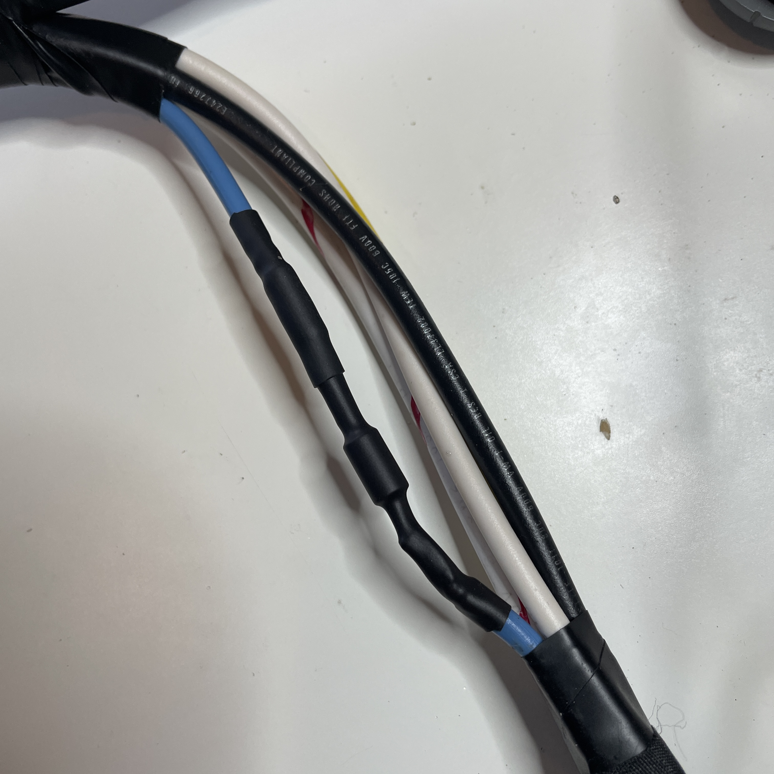
Let’s hope it works! 🤪 Thanks! Yeah, I discovered that a couple of times. It also can’t be restuck. Once you pull it off it’s shot. By the way, @SteveJ, I found that it’s possible to lessen the effectiveness of the plastic that catches the tab on the 1/4” connectors, so be careful when you pull off those colored connectors. I had to fix a few spots, particularly where a 12 or 10 gauge wire had been removed.
-
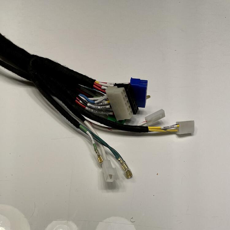
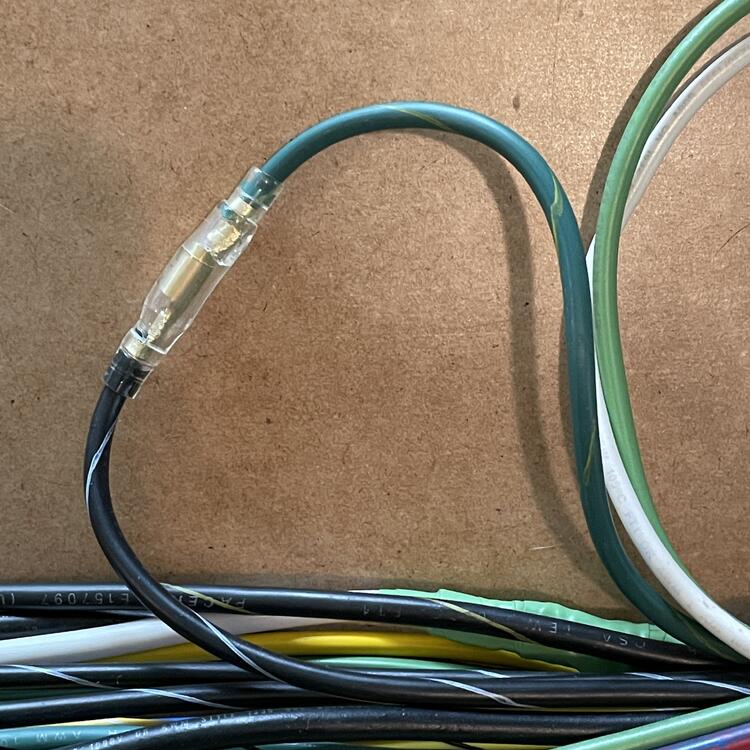
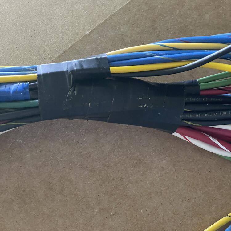
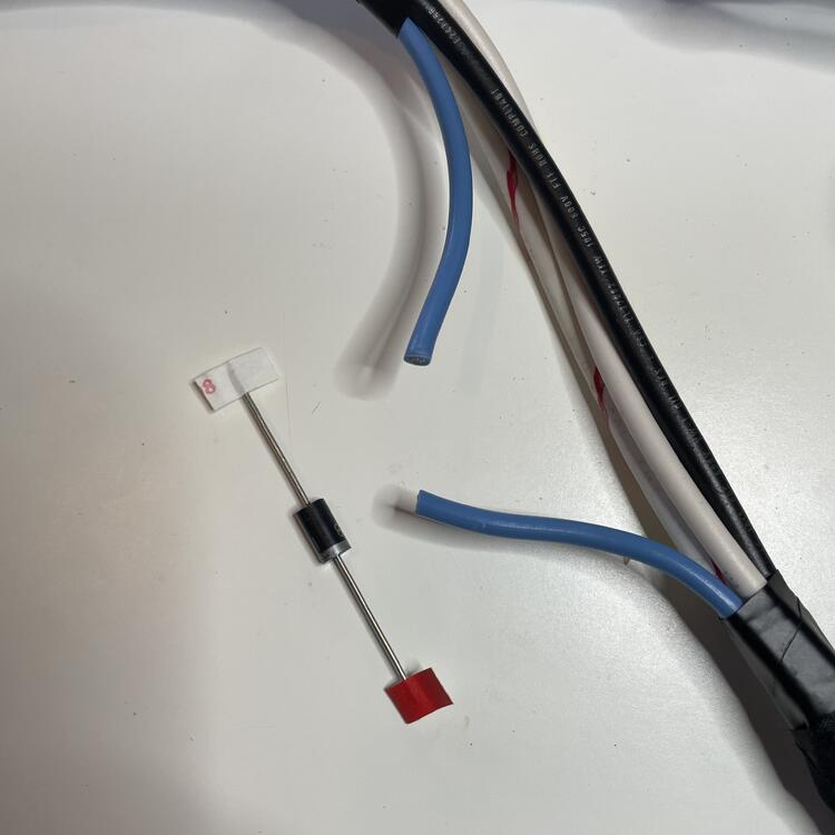
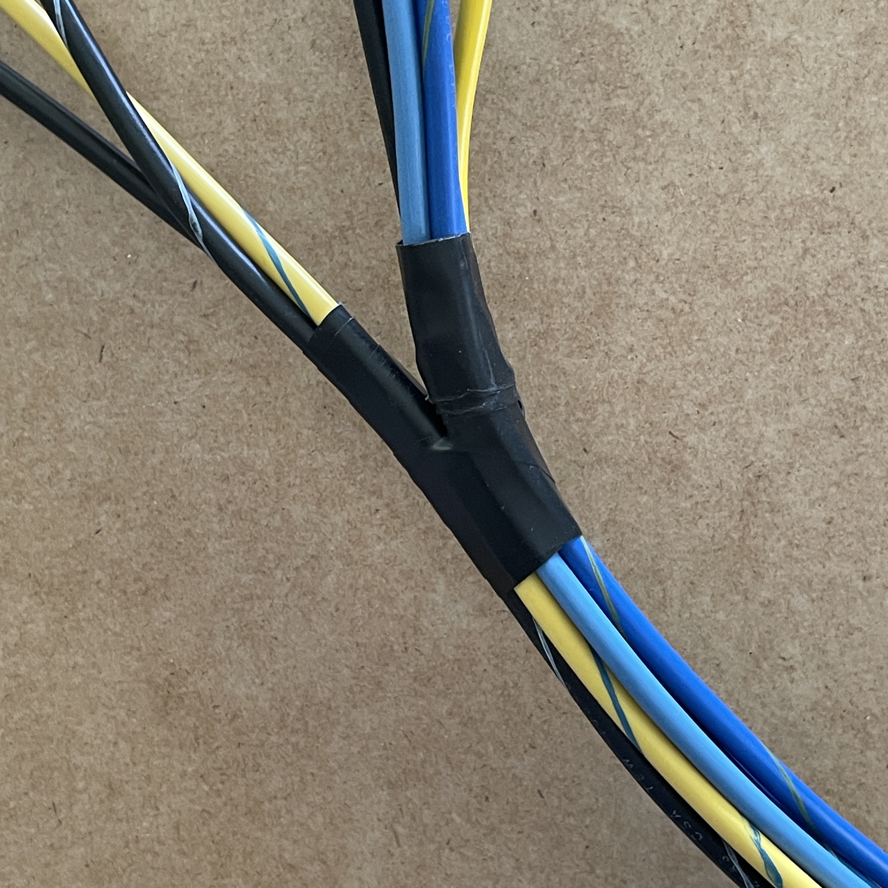
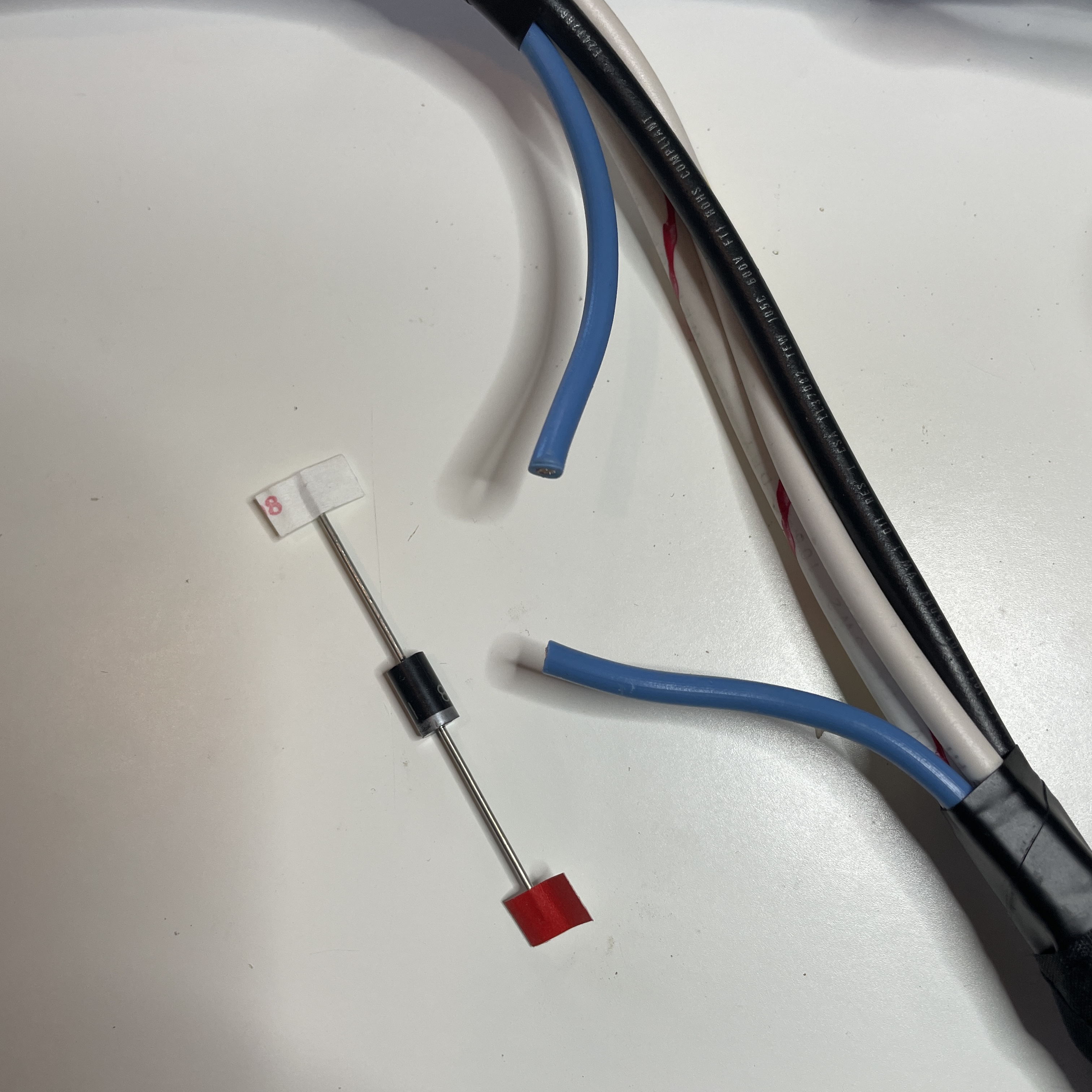
One complete (mostly) engine harness. Mostly because I am waiting for a handful of connectors to come in the mail. Once those are on I can instal it. I opted to wrap the harness in Tessa tape sealed with adhesive shrink tubing rather than use split loom or whatever. I think the taped look suits the car better and I’ve made provisions for anything I might add to the car that would need to tie into this (electric fuel pump). I used 51608 PET Felt tape on the end that is inside of the car to cut back on rattling or any other noises this could cause, but the rest of it is wrapped in 51036 PET Cloth Flame Retardant tape (their high heat chemical resistant stuff). As I was wrapping it up I realized that I had forgotten to put the diode on the Lamp wire to the alternator, so I had to splice that in. Looks okay. Good thing it’s wrapped up. I can’t remember if I mentioned this, but I opted not to splice the ballast resistor wires. Instead I made the stubby and put bullet connectors on them so the can be connected (I’m going to make a nicer looking jumper later). The reason is so if I discover that I do in fact need the 2,200 ohm resistor to make my tach work correctly with the e12-80 I won’t have to cut the harness open and can just pop it in there. And finally just a couple of shots of how I branched the wires prior to wrapping the harness. Changes from factory: Ballast Resistor delete AC pressure switch & compressor power Integrated electric fuel pump wiring (rather than separate harness) Ground wire direct to battery (-) 4-wire setup for 100 amp GM-style alternator