


Captain Obvious
Free Member
-
Joined
-
Last visited
Everything posted by Captain Obvious
-
 Thanks Mark. I'll take a look. I've read a bunch of stuff on the subject, but I'm not sure that one made my radar.
 -
Here's to hoping it's smooth and stable sailing!
-
Units difficulties occur even where the demons dwell:
-
My vote? Type 1.
-
Yes, I agree. Estimating the total length at 24" (the 6 from ball joint to wheel center plus 18 from wheel center to top of strut), you would need about .42 inches added to the T/C rod length to add one degree to the driver's side and even things up. Thanks for checking my work! So if you throw a couple washers in there, are you going to take it back to the rack again before the track day and make sure we know what we're doing? On a related note, I just got done with some suspension work on our Family Truckster and I'm currently messing around with alignment stuff on that thing. It's got four adjustable wheels and I'm poking around trying to decide if I want to try to do it myself or take it to a professional.
-
Whew! Well that's better! Glad I asked. If you want to push both sides to five degrees, you should be looking at about .94 on the left side and .63 on the right. Or if you just want to make them the same, you want your fairly thick washer to be about .3 more on the left than the right. Of course, remember that I'm no suspension expert and I reserve the right to have completely screwed up those calculations!!
-
Well ballparking the length of the strut body from top mounting bolts to wheel centerline... I'm estimating that length at about 18 inches. And with that length of 18 inches, then the longitudinal shift resulting from 7 angular degrees pivot around the top mount would be about 2.2 inches shift. I gotta believe there's something else going on. I can't believe you need to push your wheel spindle forward 2.2 inches!! That chassis was rusted, but not accordion crunched, right? Are you sure there wasn't some confusion about positive and negative directions? Maybe their alignment rack was made in Australia? On my car, I can stand alongside the car with my body centered along the line created by the two top strut mounts and look down at the wheel. I can tell that my spindle tips are farther forward than the line between the strut tops. In other words, I can SEE some positive castor on my car. Never measured how much, but it's enough that I can tell which direction it is.
-
They changed a whole bunch of sheet metal all over the car in 77, including that rear area. And because of that, the 77/78 situation is more complicated. For your 75, you've got all sorts of options. "Help me I'm missing something!" Rust? You're missing rust, right?
-
The length of the needles isn't the problem. It's the diameter. The length only matters at WOT high load conditions, and even then, they were probably long enough.
-
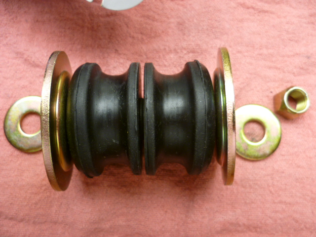
Yup. Domes in, and small washers on both ends.
-
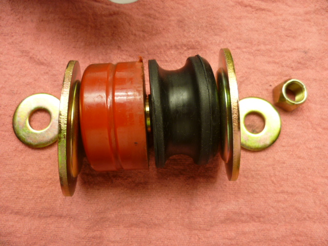
Haha! Yeah, I know the welds didn't have to look pretty. I was just busting your chops. I got no room to talk! So, about the tension rod bushings... Here is the correct orientation for the washers and the bushings: Or, if using poly, the poly goes on the front and rubber on the back: I didn't have any troubles getting the nuts started... Are you doing this with the suspension loaded, or the suspension hanging?
-
Yup. The BFI method still works. Glad you got those rear bushings done. Not sure I would have posted pics of those "welds" though... I think I would have kept them to myself. Are you sure you had the gas turned on? I know exactly what you mean about going to the home improvement stores on the weekends... I try to avoid them too!
-
Nice! I can tell you have plumbed some air lines in the past or have some help from someone who has. So where is the body off to? Chemical dip? Paint work?
-
-
Yes, the arm with the gear on it is supposed to pivot freely on the parking brake linkage, and yes, they rust up and stop working. This pic was taken to highlight the parking brake seals (it wasn't taken with the intention of showing the pivot function), but you can see how the arm with the gear on it is at a weird angle with respect to the rest of the assy: As to how to get it free? The usual... Oil, patience, persuasion, heat, etc. I don't have any silver bullets.

-
I'm going to go a little more conservative on the description of how they work... The whole wheel cylinder is SUPPOSED to slide on the backing plate, and it is SUPPOSED to center itself from the force. Just like a floating caliper with one piston, these are floating cylinders with one piston. And from the lack of chatter here on the forum about rear brake problems, they seem to work well enough. However, my experience is that I always had one shoe wear faster than the other. I think the 77-78 dual piston fixed cylinder design is way better, and if you're ever replacing rear wheel bearings, I'd take the opportunity to upgrade to the newer design.
-
The "ER" is just a typo. It should be "SEATER", not " SEAT ER". Also, l think your assumption about the second one being for the auto trans is a good one.
-
So how many applications of paint remover did it take you to get down to clean metal? Just one with the plastic wrap? Or were there still multiple apply, wait, scrape cycles?
-
My guess is it's a normal USA 74 2+2 260 with a title mistake.
-
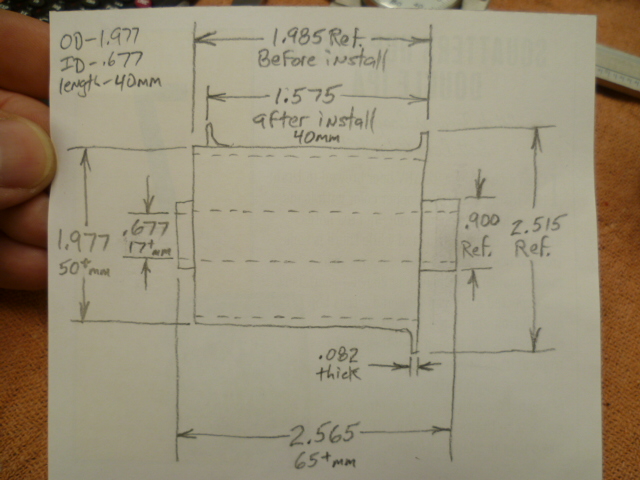
I've never seen a good dimensioned sketch of the washer ends. I'd be interested if you want to make one up! Are the two stock washers the same, or did they have different hole diameters in the middle to account for the bolt they ride on?
-
Here's a rough chart that can give you an idea of the relative hardness of rubber and poly: My thought on poly replacements is they are (obviously) better than nothing, but will never be as compliant (or quiet) as the original system. With the original system, the only points of contact are through the rubber bridge of the bushing, and the raised tips of the rubber on the flat washers. With poly, you usually have much more contact. At least that's the case with the current design poly bushings. Also, I'm not sure about the flexing abilities of poly. By that, I mean, I know what happens to rubber when it flexes and flexes and flexes a whole bunch of times... Pretty much nothing. But what happens to poly when you flex it a couple thousand times? I suspect it cracks a lot more readily than rubber of the same durometer. So the tipping point would be to make it as soft as possible without it being soft enough to bend enough in application to cause it to fatigue and crack.
-
I thought we just went through this? In this thread: http://www.classiczcars.com/topic/58037-mustache-bar-bushings/?do=findComment&comment=525900
-
-
Have you ever had a complete failure of half the system while driving? I never have, but somehow I just doubt I would have the wherewithal to pump the brakes to shuttle the plunger to the end: Pedal goes to the floor. Brain goes "OH SHITE!!" and I freeze looking for an exit path. Foot planted hard on the floor. In fact, at that point, I'm probably trying to push the pedal THROUGH the floor. Brain never goes "Just pump the brakes a couple times to shuttle that plunger to the end of travel and you'll get some pressure back".
-
The first block (the one closest to the master cylinder) is the brake warning switch. It doesn't proportion, it just lights the warning light if there's a failure in one axle of the system. The second block (the one on the firewall) does the proportioning. It's a little weird looking, but since the warning switch is mounted close to the LF wheel, they pulled the line off there to go to that corner. The pressure there will be the same as the RF, but it was just easier to pull the plumbing connection off there instead of pulling another front connection off the proportioning valve and backtracking to the LF corner.

