Captain Obvious
Free Member
-
Joined
-
Last visited
Everything posted by Captain Obvious
-
 Unbelievable.
 -
That looks reasonable. Hope that's the end of the issue!
-
I don't know about your side of the border, but on the US side, I'd get 'em from McMaster. Here's the through version with seals on both sides https://www.mcmaster.com/5905K586/
-
Hahahahaha!!!
-
Thinking about this a little... Most of those drawn cup needle roller bearings are available in a configuration where one side is closed off. Totally blind. If one finds that the vacuum leak past the bearings is objectionable, they could use that closed end variety on the outboard ends of the carbs. That would completely eliminate two of the four potential leak locations.
-
Didn't Madonna wear those?
-
It looks like they "thinned" the web on the original throttle shafts. You can see the underlying brass where they cut the shaft down. You know.... For higher performance because it reduces air resistance at WOT.
-
That is clearly not the way things are supposed to work and the first thing I would do is put the vapor tank back in. Only thing that confuses me is you said you were getting liquid in the vent line even before you took the vapor tank out? So you were getting liquid in the vent line with a stock configuration vent tank and hoses?
-
Neat modification. I don't think the seals on those bearings are rated for vacuum or pressure though. I think the seals are only intended to keep grease in and dust out. That said, I wonder if the ensuing leak would be any more or less than the original sleeve bearings. I'm also pretty sure the chrome plating on the shafts would not be recommended by the bearing manufacturer. And if the chrome plating has already been worn off in spots exposing the soft brass underneath (as is so common with used shafts), there's no way it would be recommended for those rollers. However, with another "that said" here... At low speeds you will see in this application, would the rollers still be better than the original sleeves running on the soft brass? I'm no bearing expert.
-
When you get gas, do you top off the tank to the very top or something? Just looking for theories.
-
Excellent. Well, not the "forget' part, but the part that it works well.
-
Have you made changes to the way your tank venting is done? Anything other than replacing failed / leaky hoses? I don't remember what you have done back there. And I think you are supposed to have the "check valve" device installed in the vent line running from rear to front. You're saying you don't have one?
-
And everything works as intended?
-
I don't know anything about knock sensors other than they are piezoelectric. Piezoelectric materials change shape when a voltage is applied to them, and conversely... when a piezoelectric material is subjected to a shape change, it generates a voltage. That's about all I know. Do you have any links or learning sites that do a good job of explaining more detail than that? How this pertains to knock sensors?
-
There should not be liquid fuel in that vent line. Wonder how that happened.
-
Maybe if I put it a different way? Where Does that help?


-
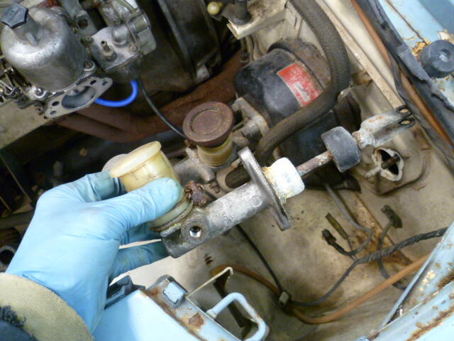
My little eye spies the wrong clutch master cylinder. It's a Nabco, but it's the new style. You guys are all gonna regret me seeing an early car with my own two eyes. Hahaha!! You need one of these. Maybe not quite as crusty, but this style:
-
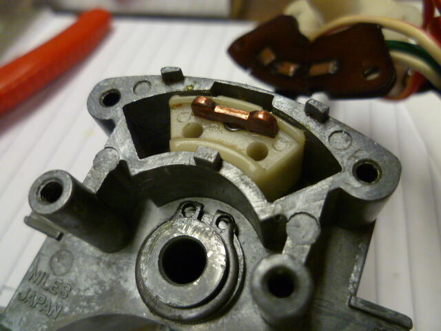
Here's a couple other pics that might help get the barrel out of the housing. It's been a number of years since I was into the locks... You may need to have the key installed in the lock in order to get the barrel out. You can see the retaining tumbler at the back of the assembly. Press that down and the barrel should slide out: And once that's done, you're looking at this:

-
The hatch lock is one of the easiest to deal with. Just don't break the little tabs off the facecap.

-
You should be able to pull the plugs and get a view of the piston tops. Won't tell you what your compression numbers should be, but at least you will know if the pistons are dished or flat topped.
-
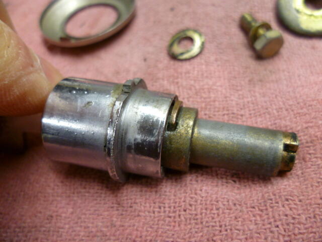
Yikes. Yeah, that sleeve has seen better days! And I'm assuming there was corresponding wear on the bushings as well. The original bushings are oil impregnated sintered material, but mine looks like there is also grease in the groove between the two bushings. Yours was clearly beyond salvage and I'm glad your repair job fixed you up! I'm hoping with fresh new grease on mine, I can leave that part of my pedal alone.
-
Will do. As soon as I know that this whole thing isn't a disastrous failure. Parts on order...
-
Sorry I missed the show. I was working on a Z... That counts a little!
-
Got it, thanks. I've got a goal now!!
-
Are you talking about the little brass piece that fits in the slot in the plastic block?