Captain Obvious
Free Member
-
Joined
-
Last visited
Everything posted by Captain Obvious
-
 Agree with the above... For a gasket that simple, I would just pick up some gasket material and make my own. So did you ever do an intake manifold vacuum test? Would be a good benchmark to see the improvements you're making as you go along.
 -
In the olden days, they were adamant about getting the U-joints back together the same way they came apart because everything was balanced that way. In today's more consistent manufacturing plants, they don't seem to be as adamant. I didn't check the FSM... Do they mention anything about that?
-
What he said. And that gasket is definitely a very important one because it's on the high vacuum side. Same thing with the cold start valve. If they didn't put a gasket on the AAR connection, maybe they didn't put one on the cold start either? I'd use a tiny bit of RTV on those gaskets. Some details about that here: https://www.classiczcars.com/forums/topic/65119-tuning-with-an-airfuel-gauge/?page=2&tab=comments#comment-617333
-
Let's see... I think that would be 2 to the sixth power, or 64 different combinations. So happy hunting! LOL. In reality, I doubt that the configuration at one end of a shaft would have much impact on what's going on at the other, and I also doubt that what's going on with one shaft would have much impact on any of the other shafts. So if those assumptions are true, you could narrow it down to three sets of four combinations, or 12. I was going to suggest that the answer was 42 and just leave it at that...
-
LOL. My Barracuda was in the shop, so I was in a rented Stingray. And it was overheating. So I pulled into a Shell station.....
-
Good luck with it, and let us know how it goes. One fix at a time!
-
Is there room in one of the back panels to put a hole for the valve cover breather as well? Asking for a friend. @Av8ferg
-
Yup. Details are important and all that kind of stuff is killer on the system. And don't beat yourself up. The good part is you're finding stuff that needs to be addressed. happens to everybody! The mixed up nipples on the throttle body probably wasn't causing a big issue, but if the lines on the air regulator are leaking, that could be a big deal since some of those lines are on the high vacuum side. I believe the only function for the TVV is to enable or disable the EGR system in response to engine temperature. When the engine is cold, they disable the EGR system so it doesn't make an already struggling idle worse. And then once the engine warms up and the idle is strong and stable, they allow the EGR system to operate. If you have deleted the EGR, I don't think the TVV has any purpose anymore. However, about removing the TVV completely... The TVV screws into a heating plate that also warms the idle air regulator, and even if you aren't using the EGR system anymore, the heating plate still adds value to the AAR. So you can cap off the TVV stuff, but probably don't want to take it (and the heating plate) out completely.
-
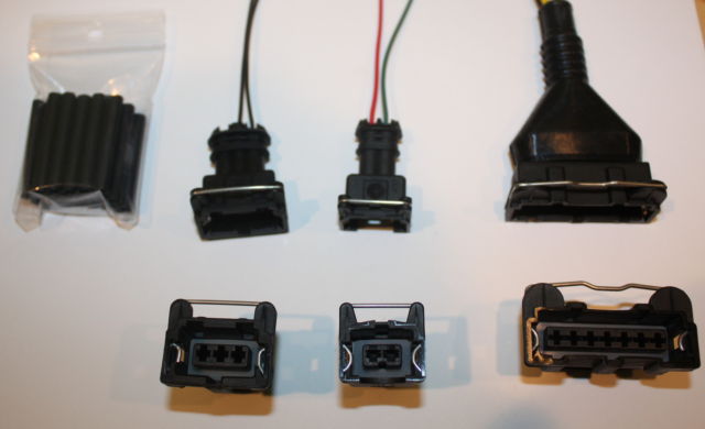
One of the most common areas for issues with the fuel injection system is the electrical connectors going to the injectors and the sensors up in the thermostat housing. The original ones are likely corroded, cracked, and unreliable. And even if they are in good shape, the way the retainer clip works makes them a PITA. Here's a pic of a common style of connector people use to replace the original Bosch connectors. The retainer clip works different. With these, you just squeeze the retainer wire and it releases from whatever it's connected to. Much more convenient than the original design. Looks like this:
-
OK. I've got a whole F54 setup here... Block, crank, caps... But the block block casting itself is no good*, so I don't mind selling the caps off separately. The crank is also available to a new home if anyone is interested (shipping prohibitive). *There was an ummm.... mishap during the rebuild process. I believe the technical term is "oopsie".
-
Are you struggling with and just trying to get your Z on the road so you can enjoy it for years to come, or are you flipping this vehicle? Just need to get the engine running long enough for someone else to test drive it and buy it? In other words... Are you planning to put this engine together and drive it yourself, or are you planning to make it someone else's problem? Haha! Honestly, I'm not really keen throwing caps in there from a different motor and then dumping it in someone else's lap without telling them about it. Does that make sense?
-
You can see the dents in the jacket where the swaging has compressed the material. And I believe you're right about the casting part... It looks like cast zinc or aluminum to me. Neither of which is known to be incredibly formable. And yes, that was probably swaged at the factory with a press and a fixture. I would try to make some sort of fixture to swage the casting a tiny bit more and I would judiciously apply epoxy and give it a shot. Hope you don't crack the casting, and hope you don't get epoxy all up in there where it would gum up the works. That doesn't look like a fun issue.
-
@Remixaflip What cap are you missing? I've got an F54 block here that I'm not going to use.
-
Right. But unless they remove material from the block side of the journal, you aren't guaranteeing concentricity. And if you DO remove material from the block side of the journal, you'll raise the piston's stroke location in the cylinder. Bottom line for me... I'm not in the outback.
-
That would work great for a DOHC engine where the spark plug hole comes straight down from the top of the piston. Not sure how well it would work with the plug hole coming in on an angle like the Z. I'm picturing the shaft bending if the tip doesn't slide easy on the piston top. All comes down to vectors and friction. What you really need is a pivoting arm. Does such a device exist?
-
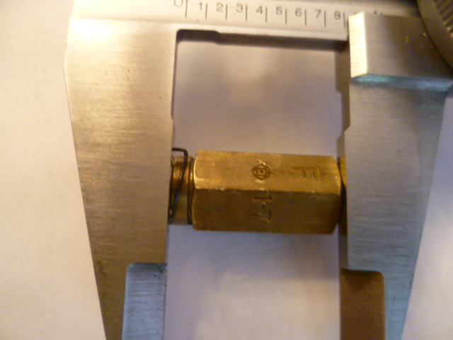
18.5mm and has an "R" on it. Perfect. You guys are the best!! @siteunseen @Terrapin Z My rebuild kits should be here in a couple days. I sure hope one of them is the long version. I really don't want to have to carve a new one myself.
-
Well I'm not sure what everyone here is talking about when they suggest line-boring, but where I come from, it would mean putting all the caps into place at spec torque, and then running a cutter through to remove material thereby making sure all the journals all perfectly in-line and the same size. But my question is... What then? You'll need larger bearings with more meat on the outside to make up for the material you took off. You got a source for that? You can get "oversized bearings" with more meat on them on the INSIDE for when the crank is ground, but to find bearings with more meat on the OUTSIDE that were designed to fit into a larger block bore? I mean... I've never looked. Is that a thing?
-
Pretty much everything these days depends on where you get your news. Here's my guide: If you think your reliable news comes from something down in the lower left like "Occupy Democrats", then I think you're off in the weeds of unreliable and untrustworthy. And same thing, if your news comes from something untrustworthy way down in the lower right like "Epoch Times", then maybe it's time to re-evaluate your news sources, Problem is, once you're mired into either of those two ends, part of the conspiracy and paranoia is designed to to keep you there. And that's probably what everyone mired down into either of the two ends would say about that media bias chart. They probably think the chart itself is unreliable. Kinda like the mental patient who is paranoid and thinks the doctors are trying to get him so he hides his meds instead of taking them. Maybe I'm just sheeple, but I want to stick towards the top tier of reliability. You can tend towards one side or the other within that top tier to find your own personal political leaning, but once you start to wander too far out of that top tier, the information, even if "technically accurate", is interpreted and presented in an incredibly misleading way. There's a reason entities like the WSJ, Reuters, CBS, New York Times have been around for so long and have a reputation for being reliable. Down at the bottom of the chart, you;d be better off getting your news from The National Enquirer. It's fake news, but at least it appears to be pretty close to the middle of the political spectrum.

-
If I were in the middle of the outback and needed to get to the hospital, I might try swapping the cap from one motor to another just to save a life. But I would never expect it to last. And I certainly would never try that on cap #4 or the rear cap #7. So unless the guy you bought the motor from turns up the missing cap, it sounds like you bought a paperweight.
-
Woof. I suspect those old injectors had been knocking around in boxes for so long, they probably started consolidating them and mixed them up. Glad to hear you're back on the money!
-
Terp, Awesome. Thanks for the great pics. And your number matches the Hitachi valves I have here. So assuming site's 72R valve comes in at the same dimension as what's in your pic, here's a summary of what I have so far. Most of this is old news, but just to put it into a form that my little brain understands... The float valve for the 72F should be 20.5mm. That is 2mm longer than the previous years and Datsun adjusted both the length of the float ears and the depth of the valve recess of the 72F lid to accommodate that change. The intent seems to be "They wanted the front carb float level to be approx 2mm lower than it used to be in previous years." The float valve for the 72R should be 18.5mm, and it's interesting to note that this is the same length valve Datsun used on the previous round tops in 70 and 71, but a different part number*. And again, Datsun adjusted both the lengths of the float ears of the 72 R lid as well as the depth of the valve recess to change the float level. The intent seems to be "They wanted the rear carb float level to be approx 2mm higher than it used to be". *An interesting side conversation would be... So if the float valve for 72R was the same length as the previous years, why did Datsun bother to change the part number? Why not just spec the 70-71 valve for use in the 72R lid? I've got two theories about that: First is that there's a note in the EF section of the 72 FSM about how they changed from a hardened steel tip to a rubber tip for the sealing of the float valve. Second is that I've got (what I believe are) early 70 valves here and they have a different through hole. The 70 valves I have 2.0mm through hole, while the later 72 valves have a 1.7mm through hole. So while the length may be the same, they may have sprung for a new part number because of those changes. However, despite those changes, it seems to me you could use the same valve for the 70-71 round tops and the 72R. The 72F is still the outlier.
-
@Terrapin Z, @siteunseen When you guys get a chance, could I trouble you both to take a caliper measurement of the short valve going all the way to the top of the valve? Also, do your short valves have the "R" stamped on them? Looks that way in the pics, but just checking.
-
Well I guess I'm going to test that statement about the new aftermarket valves being the same front and rear. I just put in an order on rockauto for rebuild kits for the 72. They call out two different part numbers for the kits and make it clear there is a different one for front and rear. So I'm going to soon see why they spec different kits for 72 F and R. If it's not the needle valve length, then I don't know what it's gonna be. I guess I'll let you know in a little while when the kits get here!
-
Oh, and it's clear to me that Datsun really messed around with stuff in 72. The float valves are unique, the lids are unique, everything is different than the previous years. It looks to me like they were chasing minutia. Some engineer realized the slight geometry differences between front and back carb bowls when they mounted on the car and convinced management he could make it better. I'm thinking they should have just left well enough alone. Also makes it clear why I was having a hard time getting these carbs right... They're all kinds of wrong inside from previous owners.
-
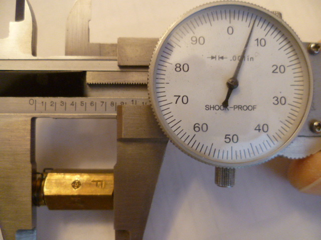
Yeah, I'm measuring including the rounded top portion. Essentially I'm interested in "how far does the valve stick out of the bowl lid", and that includes more than just the hex portion. So I'm measuring everything from the sealing washer surface to the top of the valve (not including the movable internal bits). Like this: So this is my (cracked body) 72F valve. I get .806 (20.5mm), That makes sense since the TSB mentioned earlier says they lowered the bowl level for the 72 front carb by 2mm. Both the valve and the bowl lid ears got 2mm longer for the 72F, so all the numbers line up to support that: So when your eyes get back into focus, let me know.