Captain Obvious
Free Member
-
Joined
-
Last visited
Everything posted by Captain Obvious
-
 Yeah, once you know what you are working with, it's easy to get it apart even without the correct key. Been a while since I've been into the locks and I don't remember which direction the tumbler springs push with respect to the "walls" inside the barrel, but it may be as simple as using an uncut key? If not that, then some rudimentary lock picking would be the trick.
 -
Phoned a friend! Haha!! Glad to help.
-
Sorry, but I can't view that attachment. Whatever format that is, my system can't deal. Can you post a .jpg or a .pdf?
-
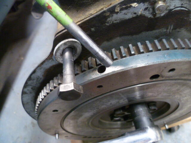
This worked great for me. Both with loosening, and then re-tightening with engine out of the car: I'm not sure if all the flywheels had these holes along the outside edge, but I used a tight fitting punch (8mm or 5/16) in the hole and then blocked rotation with a bolt threaded into the block: This may be old hat to you engine guys, but it worked great.

-
Well it sounds like you have narrowed the issue down to an ignition electrical issue, and not fuel. That's a big step. So it may be temperature related, but at least we know it's not (directly) related to the fuel supply. Can you post a pic of your thermostat housing?
-
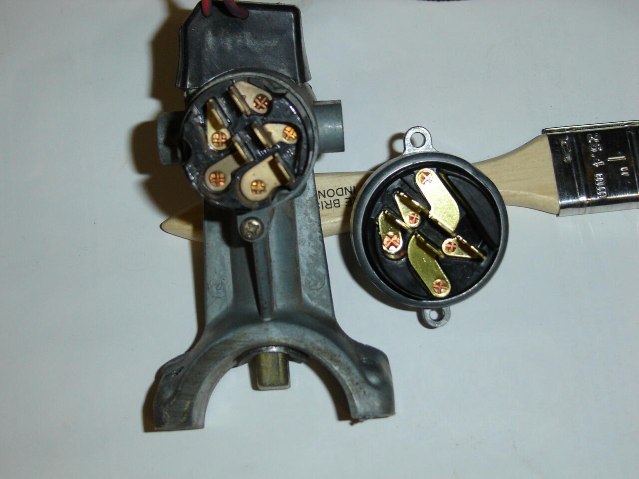
So the unusual nature of this issue has me intrigued. I know you said you were going to have the combo switch thing rebuilt, but in the meantime, I had a question. Are you running an old style single screw mount ignition switch, or has the whole assy been replaced sometime over the years with the newer two screw style? Here's a hoovered pic of the difference. Older single screw mount on the left, newer two screw mount on the right:

-
Yeah, that temp gauge is a little disconcerting. Even if your logical mind knows that it's an instrumentation issue and not a real temperature issue, just looking at that thing would drive me nuts. So while you are in there, are you happy with the location of the oil pressure readings? Because if you're going to be into the guts of the gauge, that would be the opportunity to adjust the OIL as well.
-
I figured. But it was worth a look!
-
So I did a little thinking and looking and I have a theory.... This time a little less knee-jerk. If the brake light only comes on in the LOCK position, my theory is that you plugged the connector onto the back of the ignition switch 180 degrees out of position. I don't have a harness here to see if that's physically possible or if things are mechanically keyed, but if there is no key, you might have done that? I admit, it would be unlike you to do something like that, but who knows... In a flurry of hurried activity, not lining up the unpopulated connector cavity and all that? And if you did, it can cause exactly what you described.
-
Oh wait... Sorry, I missed that detail. The brake light is on when the key is in the OFF position!!! So all that stuff I wrote... Forget all that. It's more complicated than just a brake warning switch. So I'll shut up here and wait while @SteveJ provides some REAL help instead of the knee-jerk blather I posted above. I mean, your brake warning switch may still be screwed up, but there are some electrical gremlins at work here too.
-
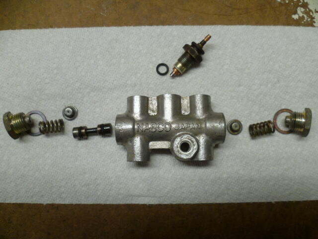
Short answer? Because your brake failure switch is indicating a brake failure. In other words, the switch is closed. Long answer? I'll let @SteveJ work you through it! But I suspect the problem in inside the brake switch. Something like your little slidey piston is all gummed up and stuck on the "fail" position: Or maybe one of your tiny metering orifice holes is gummed shut with 50 years of gelatinized brake fluid and deteriorated rubber:


-
Yeah, it's always it's a little risky to go running more fuel lines all over, but I really think you need to do that. Make sure you have a good fire extinguisher with you, just in casel. In the meantime, I'll think a little about where to go next if you come back and tell us the fuel pressure numbers are just fine under load even when the engine isn't running properly.
-
Then, in this pic... You see the little screw? That's an adjustment screw for the gauge. Make the contacts tighter, it should read higher. Make the contacts looser, it should read lower:

-
First, have a look at this thread that details how the gauges work:
-
It's not the same. It takes a lot less fuel sitting still at 3K sitting than driving around. The load is so much lower. Try this... Sit in the driver's seat and with the engine running, push the gas pedal down until the engine is spinning at 3K. Note how little pedal it takes to do that. Way less pedal to do that than do drive around under load. Hope you can make some headway with this issue. I'm sure you're tired of dealing with it.
-
Those numbers all look fine. I am a little concerned that you would be loosing 2 psi between the pump and the engine compartment, but that could just be different measurement methods or gauges. And those numbers are under low (or no) fuel demand conditions. I'm still wondering about some delivery issue that is only apparent under higher load conditions. Maybe you could tape your phone inside the engine compartment aimed at the gauge and take a short video? So about that whole front fire thing and looking for vacuum leaks... Make sure you take a good look at the rubber boot that fits between the AFM and the throttle body and all the associated hoses connected to it. PCV, etc. If you popped a crack in that boot, it'll run lean. Or if you damaged your PCV hose it will also.
-
Me too. You shouldn't see 36 psi at idle under normal conditions. You should see 36 minus intake manifold vacuum. Can you double check these numbers? Zed-head questioned the numbers found here, and I agree. I don't get how the idle is richer with the line connected, and ZH questioned how the car can be having a performance problem with WOT numbers like you're getting. - after hose change (with FPR vacuum line connected): idle 14.7, cruise 16-19ish, WOT 13.7 - after hose change (with FPR vacuum line dis-connected): idle 16.9, cruise 15ish, WOT 12.8 There is a small inlet screen on the stock fuel pump. Is there anything like that in your aftermarket replacement?
-
Wow. Glad you're still around, but what a chain of events! Hope it's greener pastures from here!!
-
Arrrrrgh!!!
-
At idle, you SHOULD be seeing around 30 psi. If you goose the throttle, it should shoot up to 36 for a brief period. But at steady state idle, a reading of 30 is not a problem. That fuel pressure spec is a differential reading. Think about it this way.... There should always be 36psi across the injector. Fuel line pressure on the inlet side of the injector, and intake manifold pressure (vacuum) on the other. If the manifold vacuum is 17 inches of mercury (which converts to around 6 psi of vacuum). You need to subtract that six psi from the fuel pressure in order to maintain the 36 psi differential. Fuel line pressure - manifold pressure = desired differential across injector (which is 36) 30 - (-6) = 36 << fuel line pressure = 30 When you are at WOT, the intake manifold vacuum is zero: 36 - 0 = 36 << fuel line pressure = 36 Does that make sense?
-
Yup. Set-up to run with the nozzles about 2 1/2 turns down, I measure the same as you. Then with the nozzles turned all the way up, it's closer to 1/2 inch. So it sounds like you're making good progress with the nozzle sticking issue. Cool.
-
I don't know what's going on yet, so I'm not ready to let the pump off the hook. Is there a way you can see what happens to the fuel pressure while you're driving?
-
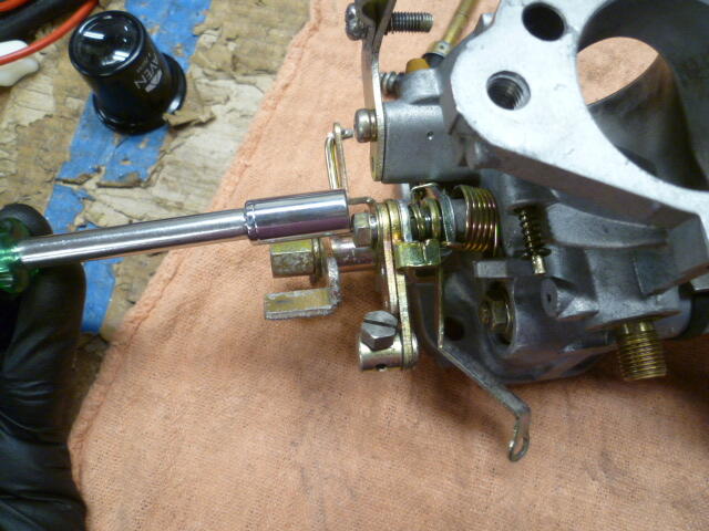
And by "something weird", I mean, maybe the annoyingly complicated nugget of springs and levers and stops etc. has an issue:
-
I measured the nozzle drop on a set of four screw carbs here and (with the nozzle nuts turned all the way up "home") I get about about 1/2 inch. If you're really getting 1" drop on your troublesome nozzles, then there's something weird going on.
-
Done!! Let's hope it doesn't come to that, but if it does, I'm all over it!!