


Captain Obvious
Free Member
-
Joined
-
Last visited
Everything posted by Captain Obvious
-
 I would think the highest amount of info would come from two readings... 1) With the engine off, and 2) While the problem is occurring and the engine is running. And just to be able to keep the analysis simple... I'd measure it to the alternator body (ground on the body itself).
 -
My thoughts on the matter are in the form of a complaint... I don't like the condition description of the parts. I find it deceptive. There is no mention that the part is 3D-printed, and in fact, I find it easily misconstrued as an original part. For example: "New: A brand-new, unused, unopened, undamaged item in its original packaging (where packaging is applicable). Packaging should be the same as what is found in a retail store, unless the item was packaged by the manufacturer in non-retail packaging, such as an unprinted box or plastic bag. See the seller's listing for full details." Of course it's new. Of course it's in it's original packaging (because since he made it, "original packaging" would be whatever packaging this guy puts it in). And of course it's the same as what's found in a retail store unless it isn't. Maybe it's just me, but I find it deceptive. I think the condition should be "New aftermarket 3D printed reproduction part.".
-
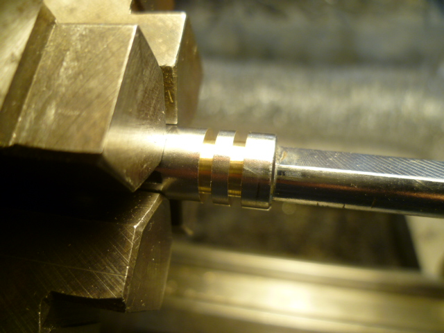
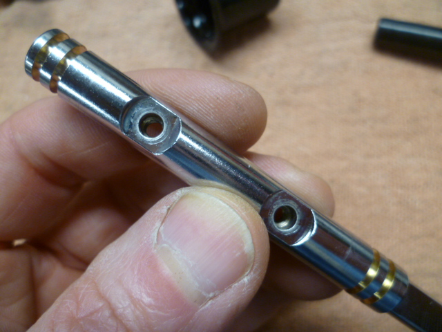
First Q - Depends on your definition of "needed". I've seen junk in those filters, so I consider them cheap insurance as a "last chance" filter. Would catch anything that comes off the inside of your fuel pump or the rubber hoses between the main filter and the bowl. As mentioned above, they are still available (for the round tops) and they're not that expensive. I'd run 'em. Second Q - No. And I doubt the real issue is the bushing. I bet the problem is more the shaft than the bushing. Once you wear through the hard chrome into the soft brass underbelly, it wears pretty easily. You comfortable with precision stuff on your lathe yet? Third Q - My (non-expert) method is to use a thin layer of rubber sheet (1 mm thick rubber gasket sheeting) on the jaws of your bench vice. The rubber provides a little stickier surface to grip the needle along with some cushion and compliance to spread the force. Grip up high, slight twist and pull. Don't chew your needles up with pliers.
-
Yeah, I probably should have prefaced my post with "In my limited, ancient experience...." Haha! So hope the parts work out and whether they are good enough or not, I find the fact that the people here are willing to jump up and try to help out by making parts i fantastic. One of the reasons this is the best forum!
-
Exactly. That will take care of it. Failures like this are really intriguing. When the "impossible" happens. I will have to look at the gear train and flow of power, but I wouldn't have thought that portion of the gear train was even under stress when that failure happened. He was in 1st gear, right? And the wheels locked up and skidded to a stop after the "bang"?
-
Starting in 77 they included a groove along the top of the stainless window trim to accept a piece of rubber stripping. I don't have any pics handy, but can snap one if you want to see it. Just another reason that the 77s are better.
-
Sorry. Not intending to imply that you didn't... Just highlighting the details in the design to save you the potential trouble that I went through once. I once had a leaking slave cylinder that needed attention. Since the rubber hose looked fine, my plan was to unbolt the slave cylinder off the bell housing and unscrew it from the hose and then simply screw the new slave on in it's place. The thought was that while the rubber hose looked great, the mounting tab fitting welded to the body was a little rusty crusty and I didn't want to mess with potentially breaking it off the body. Simple plan, right? So the main portion of the plan worked great. Got the cylinder off the bell housing no problem and the new one went on fine, but the problem was that it was now pointing just about 180 degrees in the wrong direction. The hose screws into the slave and stops where it stops it when it's tight. And if that happens to be in the wrong direction, so be it, You either MUST deal with the rusty crusty other end, or mount it up the way you PO did it. I'm thinking they decided that twisting the hose was better than cracking the other end free. All that said, if you're replacing the hose, you'll have both ends loose so it shouldn't be an issue. Just don't save the cylinder mounting for the very end. Save the double flare fitting for the very end.
-
My experience with connector shells is that there are very tight dimensional tolerances and very thin walls. I would be surprised if connector shells like that could be successfully printed. Not to mention the brittleness vs. flexibility of the printed materials. Hope I'm just being pessimistic and it works!!
-
Thinking about it a little mire... I've not been inside a Z transmission, but here's some thoughts: I'm not so sure welding the washer and nut together is a good idea. My read on the way it was designed is that locating feature on the washer (whether it's a ball or a pin like the later design) is that feature exists exactly to isolate the nut from any rotational forces from the gear on the other side. In other words... You've got this gear spinning on one side and a nut that could potentially be loosened (or tightened) on the other side. They wanted something in addition to the peen on the nut to prevent that nut position from ever changing. So they used that locating feature to keep the washer from ever spinning with respect to the nut. If you weld the nut to the washer and completely skip the locating feature, you will allow whatever rotational forces are ever generated to be directly translated to the nut. You would be counting solely and completely on the peen to prevent the nut from changing position and I'm thinking that's not a good idea. In fact, I'm thinking you've got a chicken and the egg thing going on with the failure... Did the nut loosen up and allow the ball to slip out of place? Or did the gear transmit too much torque to the washer somehow (lack of oil, burrs on the surface, debris between the two, something) and start to spin the washer. And then when that washer spun, it ripped the ball out of the hole and started to rotate the nut. So I'm wondering what happened first, did the washer (and ball) slip first which loosened the nut, or did the nut loosen which allowed the washer (and ball) to slip?
-
Yikes! That's not good! Glad it didn't shatter anything and send chunks between gears!
-
Washers and bushings look good. As Racer X mentioned... That clutch line. Haha!! When you replace it, screw it tight into the slave cylinder first. Then (after it's fully tight into the slave) put the other end into the holder bracket attached to the chassis. That will allow you to get a better routing of the rubber line with less twisting.
-
I mean, after all... The biggest improvement you could make to the original system would be to come up with an easy way to get variable speed intermittents, but that module has a fixed 7 second delay and would be no better than what we already have.
-
Well, clearly the obvious answer would be using that module to replace the original module, but I don't think that's it. TOO obvious, even for me!
-
Couple more thoughts on your alternator thing... First, if you find the overcharging issue happening again, you can take voltage measurements from both of those W/R wires on the back of the alternator. They should be identical (because they are supposed to be hard connected together inside the harness). If you find 15.5 on the large W/R and 12.5 on the small, then you've got a problem with that connection. Second, it IS of course possible that you've had multiple voltage regulator failures on multiple alternators. However, as the number of them goes up, the likelihood that you're got something else going on goes up as well.
-
I'm thinking there's a possibility you have an intermittent connection and when you move the wiring harness around to change the alternator, maybe you're temporarily bettering the connection. For the 78-83 alternator system, there should be two W/R wires going to the back of the alternator that are always hot. One big, and one small. The big W/R is power output from the alternator and the small W/R is the sense line. Those two W/R wires are connected together inside the wiring harness. I've heard of other owners finding that the connection between the two (buried in the harness) corrodes over time and becomes intermittent. That, or as SteveJ suggested above, maybe the contact(s) inside the two position connector on the back of the alternator is flaky dirty intermittent.
-
When you took the alternators back to the store, did they confirm the problem on a tester? Did they test them before they accepted them back for exchange? Reason I ask is if there's a poor/intermittent connection on the sense line leading to the alternator, it'll charge too high. And if it's intermittent, you might think it's a problem with the alternator, but actually it's a problem with the rest of the car.
-
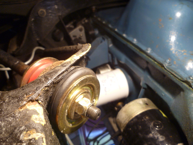
The issue with the gibberish in the manual... The manuals were scanned to PDF on a flat bed scanner and OCRed (Optical Character Recognition). Not sure why, but the OCR process for the 75 manual (and only the 75 manual) didn't do so well. If you look at the same page FA-2 in the 76 manual everything makes sense. One last thing I think I see on your pics is that there should be a smaller flat washer on both outside ends of the larger washers. Doesn't look like you have one of those on the forward side of your car. Looks like you have the big domed washer right up against the shoulder on the T/C rod. Good luck with the covid. I don't think I'm ever going to be the same. I think I'll be OK, but different.
-
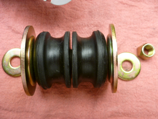
Torque spec for the torsion rod end nut - Page FA-2 of the manual says 33 to 40 ft-lbs. Basically, you should compress the rubber to the point where you have bottomed out against the metal sleeve that runs through the center and then torque to hold it there. Oh, and not totally sure, but it looks to me like you have the big washers on the torsion rod bushing installed backwards. They should have the convex side towards the rubber. Counter-intuitive, but that's the way they want it. Should be like this:
-
The wiring diagram shows three connections to the negative battery post... 1) To starter. 2) To EFI system. 3) To body. So I don't know if the wiring diagram is "literal" or "really how it came from factory", but that's what it shows. I also took a look at the 77 diagram (my year) and they only show two connections to the battery negative. My year does NOT have a dedicated connection right from the battery to the body. And now you have me thinking that maybe I should add something like that. So thanks a lot...
-
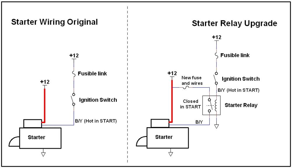
Well there's lots of diagnosis that could be done to figure out what the real underlying issue is, but at this point, if a starter relay makes it go away, then it sounds like that's going to be good enough for now. There is some extra stuff on the CA spec cars that gets engaged when the key is in the START position, but I don't know how much current it would draw. With a quick look at the wiring diagram, it looks like it would be just a couple more "lamp test" lights in the HVAC vent panel, but in your video it looks like that panel (and it's associated light bulbs) is not installed. Anyway, still hoping that the starter relay takes care of it. if you're looking for something simple to use to test some of the theories (and get you out of a jam like when you're sitting in the que at the store)? Run two wires from your starter into the interior. Use those two wires to short to the solenoid directly like you were doing manually out in the engine compartment. Put a switch on it in the interior if you're feeling fancy (push button start like the new cars ), or just connect the two wires together if you need to.
-
Oh, and... Yes, the link that feeds the ignition switch is the green one. And that schematic was originally made for 77/78. The concept still works fine, but the wire colors are a little different for 75 and 76. I'm sure you've already figured that out.
-
I like the video. I can feel the frustration through the screen. So I'm not sure if the click on the video is the starter solenoid or not. Can't tell from my seat. And as for the ammeter... I see the draw. If the gauge numbers are correct (and I have unknown to low confidence in the accuracy of the numbers on the gauge face) it appears that the car is drawing 20A or so when you turn the key to START. Question is... Is that a reasonable draw even WITHOUT the starter solenoid engaged? Does the ballast defeat and other associated functions come to anywhere near that when in START? I think I could be convinced that all the other ancillary functions can come close to that even without the starter solenoid. Let us know how the starter solenoid works out. I saw in one pic that your car is a manual trans. Did it come from the factory that way, or was it converted? Also, is your car a California spec? Do you know?
-
Oh, and adding a starter relay is a great idea regardless of the issue are having. I've seen burned up contacts inside the ignition switch caused by the solenoid current (which can be upwards of 8A or so IIRC).
-
Yeah, that doesn't help at all. So it does it... You walk away from the car to get help. Walk back with help. They turn the key while you have a hand on the starter, and it cranks fine that time. And the next 1000 times in a row.
-
Do you have access to some help in the diagnosis? Someone else to turn the key while you lay a hand on the starter to feel for the click?


