Captain Obvious
Free Member
-
Joined
-
Last visited
Everything posted by Captain Obvious
-
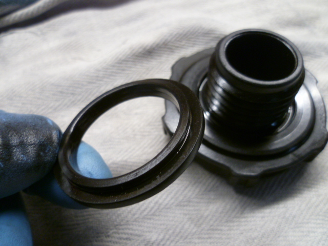
 Haha!!! Mostly just lucky. And yes... The term "O-ring" typically evokes a picture of a soft pliable contraption with a circular cross section. The seal on the filler cap is neither soft, pliable, or circular in cross section. It may have been soft and pliable at one time, but it's not now.
 -
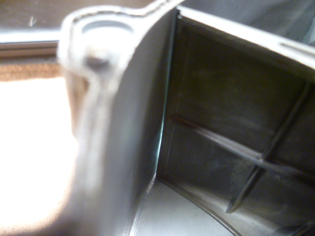
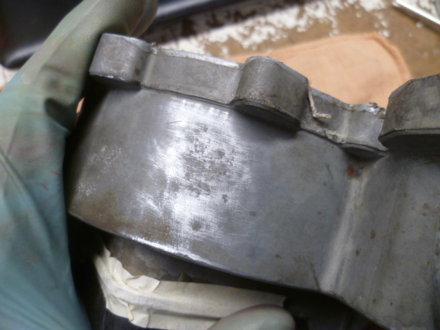
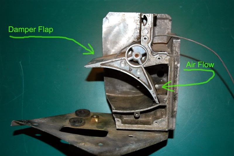
And once the cover was off, the problem was obvious. Here's a pic of the damper vane. I'm back lighting the gap between the movable vane and the case / body of the AFM. This is a pic when there is very little air throughput and the vane in the "mostly closed" position: And here's a pic of the damper vane at about mid-scale. Note how the vane is rubbing against the inside of the case: And then here is the damper vane "beyond" the sticky spot. Note that there is a gap again: So mystery solved.... The case is bent. Pushed in at that spot. Like someone dropped it or hit it with something big enough to dent the case. Note that I looked it over thoroughly from the outside and did not detect the dent. I did find an anomaly on the outside of the case, but it's quite subtle. Here's a pic of the outside of the case after some "block sanding" in an attempt to highlight the problem area. The clean spots were wiped by the sanding, but the darker spots (still dirty) did not: So, mystery solved!!! I'm going to try to fix it, but ran out of time today. I'm thinking that a few well aimed taps with a ball peen hammer might push the dent back out enough for the damper vane to clear the case.


-
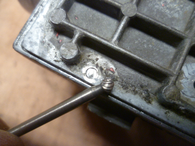
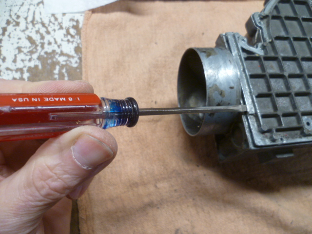
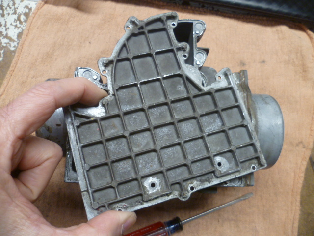
Well I went ahead and performed the surgery. Mystery solved. Goes like this: I used a small carbide burr in a Dremel to remove the smoooshed off section of the posts holding the back cover on. Here's a pic of the burr and one of the posts ground off: Worked my way all around the perimeter grinding off the posts. Also took out the two retaining screws: Even after doing that, the cover was stuck fast. The adhesive / sealant they used is quite tenacious, After some experimentation, I found that it was susceptible and softened by carb / brake cleaner. I lightly sprayed around the perimeter a bunch of times waiting a minute or so between rotations for the solvent to work into the seam: Doing that a couple times letting the solvent attack the sealant glue. Then some prying with a small screwdriver: And presto... Cover is off:


-
Well it's clear that there were some changes over the years. The one I'm messing with (which should be from a 76) doesn't have all those screws, but instead has posts that have presumably been peened over as rivets, but other than that, I would expect the construction to be pretty similar. Do you still have the one you opened? Got pics?
-
Absolutely, huh... "Are you sure about those five minutes?"
-
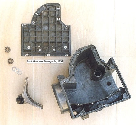
I've got some old pics that I've hoovered over the years, but it's not like talking to someone who has done it. But here's what I have: This AFM has been cut open with a saw (photo credit unknown): And here's another one that should show how the vane mounts inside the housing. Photo credit on it:
-
Well????? Pics or it didn't happen!! You're saying that taking that back cover off did not provide access to the sweep vane?
-
There was some discussion about such a maneuver in the past, but I don't know if it ever happened: https://www.classiczcars.com/forums/topic/67674-afm-loose-arm/ @chaseincats And @kickstand80, since he's a big proponent of AFM modifications and adjustment.
-
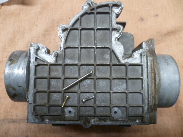
I have heard stories about sticky AFM's in the past, but I have never held one in my own two hands. Until now. So I've got this AFM here that has a binding sticky spot right in the middle of it's travel. I have looked it over very carefully and cannot see any visible explanation for the sticky spot. I'm thinking maybe the damper section of the vane may be making contact up in the belfry area, or the main shaft may be bent. At this point, I'm toying with the prospect of taking the back cover off. I remember some discussion about doing this in the past, but don't remember if anyone has actually gone through with it. Has anyone taken this back side cover off? Mine has two screws at the bottom and a whole bunch of glue around the entire perimeter: Has anyone gone through the operation, and did the patient survive? I mean... This thing is worthless to me in it's current state, but it would be nice if this was more than just an autopsy.

-
It's like one of those bar puzzles. There IS a way to do it without applying significant force. I don't remember which direction you need to rotate the lid, but there IS a way to get the lids off without loosening the whole bowl or damaging anything. That said... The REAL way to check the float level is done with the lids ON. Wet measurement with fuel in the bowl and a clear tube to see the level.
-
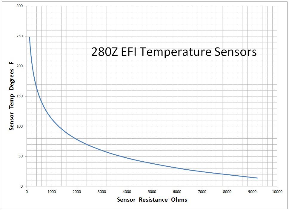
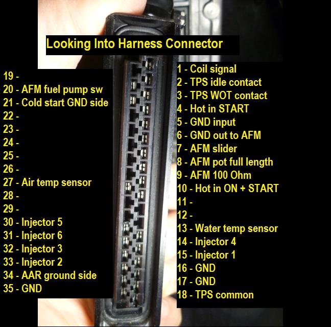
My first guess would also be the temp sensor unit. Pull the big connector off the ECU and measure resistance between (harness side) terminals 13 and 16. That should be temp sensor and ground. Looks like this: Compare the resistance measurement result to this.
-
Haha! Been laying around for ages is always nice for making a good deal. Nice story. And yes... I would also assume the hydrolic oil in your lift is NON-detergent.
-
Glad to help. I've got factory A/C parts here available for purchase if you're interested. I'm a reasonable drive from you for something bulky, heavy, and expensive to ship. Wouldn't mind seeing one of your other project cars either. Send me a PM.
-
I'm no oil expert, but as I understand it, the general theory / consensus is there would be increased wear on the moving components like the crank bearings. Goes like this... The difference between the "detergent" and the "non-detergent" oils is the ability to suspend particulate contaminants in the oil. The automotive oils (detergent) contain additives that are designed to intentionally suspend particulate contaminants in the oil. The expectation is that those contaminants will be removed from the system and trapped in the oil filter. The non-detergent oils are used in applications (like your compressor) where there is no oil filter. The intention is that the particulate contaminants are NOT suspended in the oil, but instead sink to the bottom of the crankcase where they don't do any harm. Those contaminants are removed from the system when you change the oil, or every twenty years when you break the crankcase open and scoop them out manually. If you use detergent oil in something like your compressor, some of the harmful contaminants will be suspended in the oil and continuously circulated through the system where you don't want them. Better to let that stuff settle to the bottom than have it end up in your main and rod bearings.
-
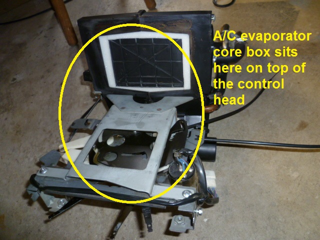
Yes. This whole box: Goes here: Now... Since your car came from the factory without A/C, there is supposed to be a simple hollow duct box sitting there, but I don't know what they did for your aftermarket A/C.

-
I did a couple different iterations up at the throttle body. The first version was to make a new piece of linkage that fit onto the original throttle that allowed for the use of the cable. And things spiraled out of control from there. The current (and hopefully last) revision is to convert over to a Nissan Sentra throttle body that originally used a cable pull. Let me look back through my pics and see what I have.
-
Not sure if he got much taller, but he's certainly wider! : And shoutout to @Mark Maras

-
Yeah, that's done for. I'm no bearing expert, but I believe that's known as "spalling". However, at this point, if it were me, I'd take the opportunity to check the body hardness and see if it was ever a possibility to drill and tap. I gots to know.
-
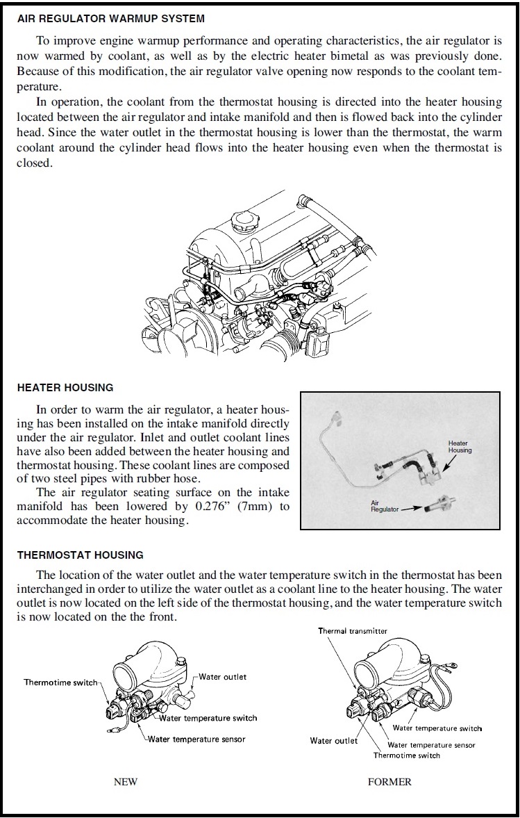
I think they ran into a couple issues with the AAR operation. First issue is that on a very cold day, the cold air going through the AAR may have prevented the AAR from closing completely. In other words, the heating coil may have been overwhelmed by the cold air stream. Second issue (and one that I have experienced myself) is the rapid cooling off of the AAR. Park the car and run into the store for a couple minutes... When you come out and start the car, the idle is bumped up again because the AAR cooled off. The thermal mass of the heating plate and the water slows that process down and prevents that. That's my read.
-
Yeah, I don't remember where I first learned that, but it's a thing, Ozone is unstable and breaks down quickly in our level of the atmosphere, but it's definitely a thing! So I would surmise those vent holes are to prevent any pressure differential between inside and out side of the starter motor from causing a problem. Whether that pressure differential is from ozone or simply from just heating up the air space inside the starter, but you want to let it breathe.
-
Serious. The electrical arcing in the motor brushes creates ozone. Here's a snippet from wikipedia >> https://en.wikipedia.org/wiki/Ozone Incidental production: Ozone may be formed from O2 by electrical discharges. Unsuppressed arcing in electrical contacts, motor brushes, or mechanical switches breaks down the chemical bonds of the atmospheric oxygen surrounding the contacts. Certain electrical equipment generate significant levels of ozone. This is especially true of devices using high voltages, such as ionic air purifiers, laser printers, photocopiers, tasers and arc welders. Electric motors using brushes can generate ozone from repeated sparking inside the unit.
-
Well not exactly. You're correct about the early tach running the coil current through it, but it's not reading it like a ammeter. It's reading pulses. Steady state does nothing. The signal has to change. If your points happen to be closed when you turn the key to the "ON" position, if it was an ammeter, the tach would peg high and stay there until the points opened.
-
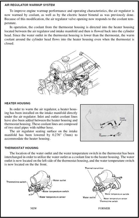
In 74, they bypassed the thermostat by pushing coolant through the carb system. In 76, they bypassed the thermostat by pushing coolant through a little heating plate that lived under the AAR. In 75, they did neither of those, so they bypassed the thermostat by putting that little bypass line in. It appears that coolant path in 75 didn't serve any other purpose other than to bypass the thermostat. Here's a snippet from a 76 Service Bulletin where they discussed the changes from 75 to 76, Here's where they talked about adding that little heating plate under the AAR: So in 76, they killed two birds with one stone... They fixed an issue with the AAR not operation correctly under all conditions, and they also fixed the issue of the stagnant coolant pool under the thermostat.
-
Actually, I don't. My data points are the most of my experience is with the later switches and my believe that they didn't ADD stuff like this in later years, only Munced down from earlier versions. I do know that I've got original switches from years as early as 74 as well as aftermarket stuff as new as a few years ago and I've never seen one with that kind of cover over those wires. Sorry if I appeared more confident than I really am. Maybe I've been missing that cover off all the switches I've messed with!
-
@Patcon, Didn't you tap a hole in a master cyl for some reason? Don't remember if it was brakes or clutch, but I do remember you doing something like that.