


Captain Obvious
Free Member
-
Joined
-
Last visited
Everything posted by Captain Obvious
-
 Fingers crossed. How will you know? Just using your nose to verify, or do you have a smoke machine?
 -
Yeah, that tool looks great. Probably much more durable than what I cobbled together. I didn't heat treat my dies and I'm not sure how many shots I'm going to get out of them before they start showing damage. Let's just hope I don't need to do a lot of bead rolling.
-
Cool. Hope it takes care of the leaks! Have you got other areas you think are leaking as well, or is the taillight the last one?
-
It's intentional. You're just the new guy providing the entertainment for us grizzled experienced owners. Soon you'll be just like us.
-
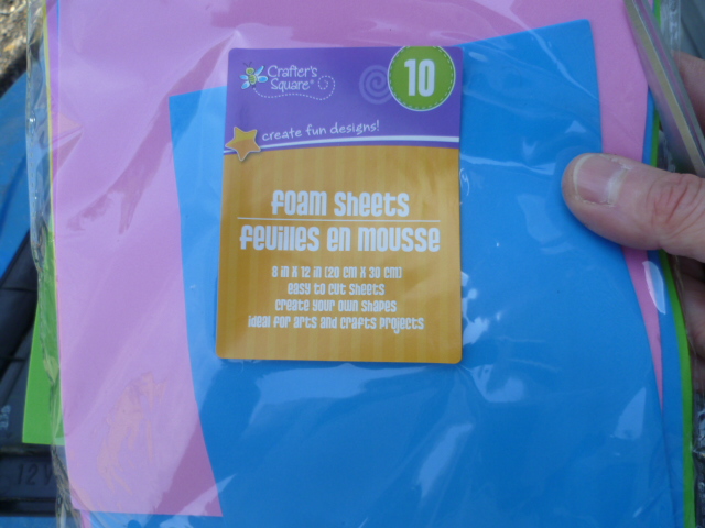
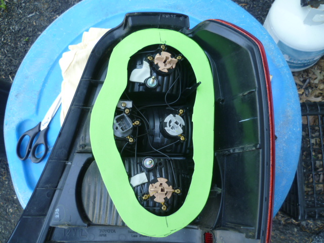
Craft foam sheets from the local arts and crafts store? That's what I did on my family truckster when the taillights started leaking on that one. Leave the original gasket in place and augment with a thin layer of auxillary foam. And maybe some seal-n-peel as well? Something like this: doesn't have to be neat... Just enough that it won't show from the outside:

-
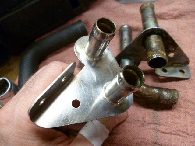
And since I can do pics again, here's my solution to the bulkhead feedthru. Not as glamorous as what you did, but more stock-ish. I made a stainless version of the original feedthru. Used the bead roller for this too. New stainless version with old crusty original in background:
-
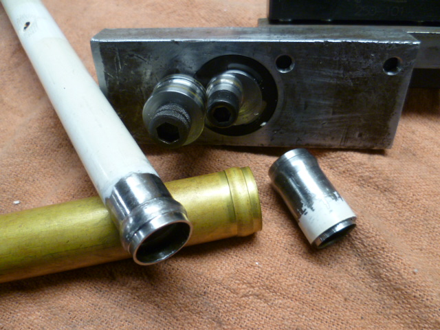
Wonder if my picture posting problems persist. Let's find out. Here's my cobbled together bead roller for when I was messing with the tubing: OK, so I can post pics again.
-
Funny... For the exact reasons you mentioned is why I thought the Seall-n-peel was a better option. I wanted something that would NOT bond (was NOT a glue), and I wanted something that took up volume instead of adhering two items together. My thoughts are if the foam alone is not sealing, it's because the foam is not thick enough, not compliant enough, or has taken a set and isn't spongy enough anymore. You don't need the foam to stick, you just need it to take up the gaps. And if the foam alone won't fill the gaps, then you need something with volume, not stickiness.
-
Agreed. Neat project. Kinda confused what he was doing in the first pic with the aluminum rod turned in the lathe, but maybe it'll all make sense to me later. The way he's clamping the part in the mill vise, that lathe work seems unnecessary? Like I said, maybe it'll all make sense later. So what bearings is us putting in?
-
I will work up a summary on what parts I used. I can quickly tell you however, that the Sentra throttle body I used was not compatible with the original TPS, and the TPS that came on that throttle body was not compatible with the Bosch L-Jet. The original is three positions (idle, mid, and WOT), and the TPS that came on the Sentra throttle body was a potentiometer. Bottom line? I spent a bunch of time adapting the original TPS onto the Sentra throttle body.
-
I'm not sure I would use that. The intent of the seal-n-peel is that it designed to take up volume, but NOT stick. It's intended to peel off (easily without damage) at the end of the heating/cooling season.
-
I used "Seal and Peel" which is a clear silicone that is designed to be an easily removable temporary seal. I haven't had the pleasure of trying to pull the taillights out since (so I don't know how bad it would be), but I've done the same on other cars and it was fine. They came off without a fight. I would post up some pics o what I did, but I'm getting the same server error as other people. But the tube looks like this:
-
Wow. Makes me really wonder if the oil control rings were installed properly. I can't imagine they wore out that quickly, but maybe put in wrong somehow? In any event, the answer will hopefully be forthcoming soon.
-
I'm thinking a PO was running a velocity stack snout or was matching the hole to the back of a non-stock air cleaner or something.
-
Yeah, that's got to be tricky. Watched the video. That's pretty blue. And if you've burned up one quart of oil already just idling in the garage, then it's pretty clear there's something internal wrong. From my armchair, it doesn't look like a carb issue. Curious though... If it is a ring issue, it would seem unlikely that there would be the same issue on all six cylinders. If the rebuilder knew how to do the rings correctly, he might have had one ring slip out of place on one piston or something. But all six seems unlikely unless there was a systemic mistake. I'm no ring expert, but there are different ring compositions. And don't some of those different compositions take longer to seat than others?
-
Yes, .100 nozzles are stock. And about the suitability of the SM needles, some people seem to have good results with them and others can't get idle to work right. I think there's a problem with the rings seating, or as Yarb suggested, an issue with the oil control rings. Why would you take it to a different shop? Wouldn't it be the responsibility of the first shop to make things right?
-
I'm guessing it doesn't do much one way or the other. Doesn't make things much better, but pretty sure it wouldn't make things worse. Did they do the same thing on the exit end at the butterfly?
-
Cool. Looks like you had a good time. And neat pics. Clear that you know what you're doing behind a camera. About the only thing I take pics of is cars or car parts. And I like the pic of that sculpture too. Looks like a nice Daydream.
-
Oh, and there was a round dimple dent in the gear plastic as well that lined up with the dot on the clamp. I got lucky!
-
I got lucky. When the factory set the proper position, they put a blob of silicone (or something) onto the clamp that holds the gear in position. The lucky part was when the PO moved the gear, it split the silicone blob into two pieces. One part on the clamp, and one part on the gear. I rotated the gear back such that the two halves of the silicone blobs lined up again. I've been inside other AFM's and the blobs are gone completely. Thankfully on this AFM, the split blob was an easy way to tell where the gear belonged.
-
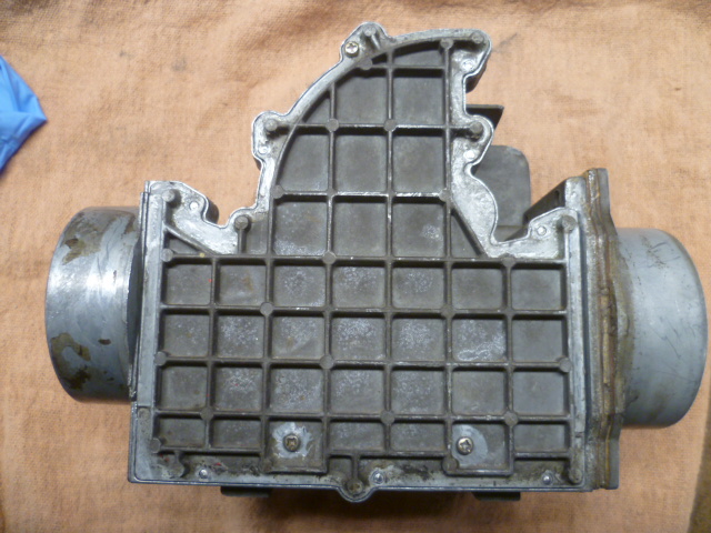
Haha! The car this is going into is running uber lean, and one of the other things I discovered while poking around with this AFM is that someone had been in there before and had adjusted the spring gear to be about ten teeth leaner than when it left the factory. I'm not sure the AFM spring is the only thing going on with the car running lean, but it's certainly something that needed to be addressed. I put the gear back to factory position and we'll see what happens when I seal this AFM up and get it back in the car. So this AFM has clearly been messed with and abused in the past by a PO. Sticky and lean.
-
OK, so the next step in the ordeal was a success. I drilled and tapped one of the places that used to be a rivet. I did one of the positions along the top. Looks like this: So now there are three screws that hold the cover on. One along the top and two near the bottom: This is just a test fit with no sealant, so the next step will be to take the cover off again and put some silicone on the sealing surface and then screw it together "for good". And after that, put it onto the car and see what happens!!


-
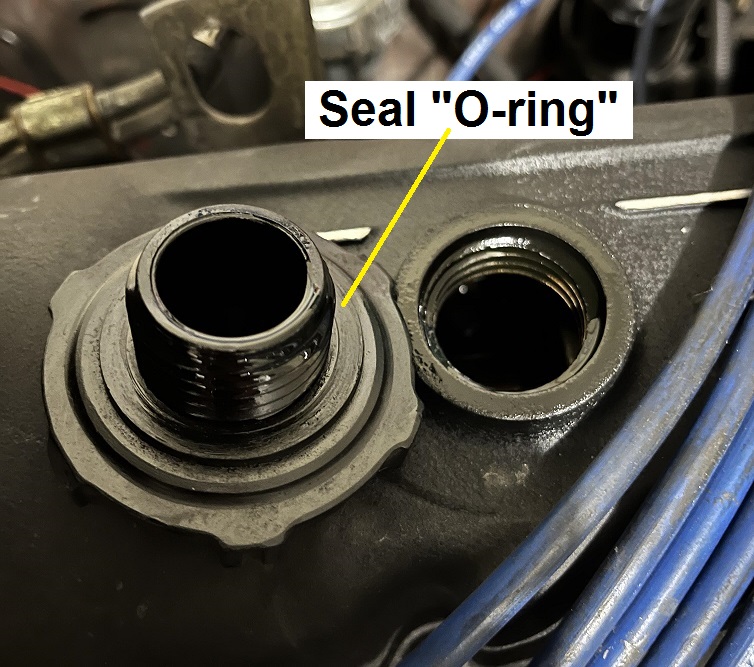
Well "hammer" and "bash" aren't the words that come to my mind... I was thinking "gently pry" with a "small screwdriver" or "pointy pick" to identify where the seams are. But whatever works! And since the cross section of the original isn't round, I'm not sure sticking an O-ring in there is going to work. It it were me, first thing I would do is clean the coating off the valve cover and use a flat file to dress the surface where the cap is supposed to seal. I don't know if it's a trick of the light, but in the pic you posted, that sealing surface looks to have imperfections on the one side. Pitting or other imperfections on the valve cover? At eight and nine-oclock in your pic? :
-
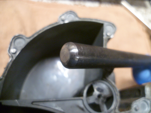
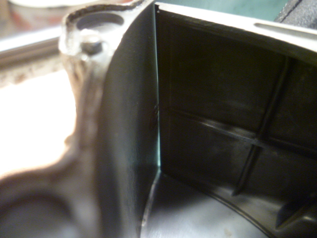
So I used a red Sharpie and marked the inside of the AFM where the interference was occurring. This is my target for bashing. Here's my target to push the case back out a little bit: And here's my drift tool. I rounded the end to try to minimize digging in and gouging the aluminum: In position and ready for an adjustment whack: And the clearance after a couple percussive maintenance adjustments It'still pushed in a little, but it clears the AFM vane: So now the AFM moves smooth for the entire sweep. Next, I'm going to work on how to put the side cover back into place. The plan is to drill and tap at least one of the rivet locations along the top side. The bottom already has two screws, so I figure if I add a third along the top and silicone it into place, it should be good enough. Certainly better than the broken paperweight I started with.


-
Thanks zKars!!


