Captain Obvious
Free Member
-
Joined
-
Last visited
Everything posted by Captain Obvious
-
 If I'm understanding correctly, you want to put a voltmeter in the console, and you want a switched voltage signal to connect it to? If that's the case, then you could just tie into the blue wire that powers the radio. It's switched, and it's already in the console harness. If all your connectors are clean, it "should" give you an accurate reading of system voltage. Oh, and BTW, the color wiring diagram you posted above is for the 77. Many (most) systems of the 77 are very similar to the 75, but there may be some differences. I normally would start by looking at that 77 color diagram, but to be sure, you should also double check the old style 75 diagram out of the FSM. Especially wire colors, etc.
 -
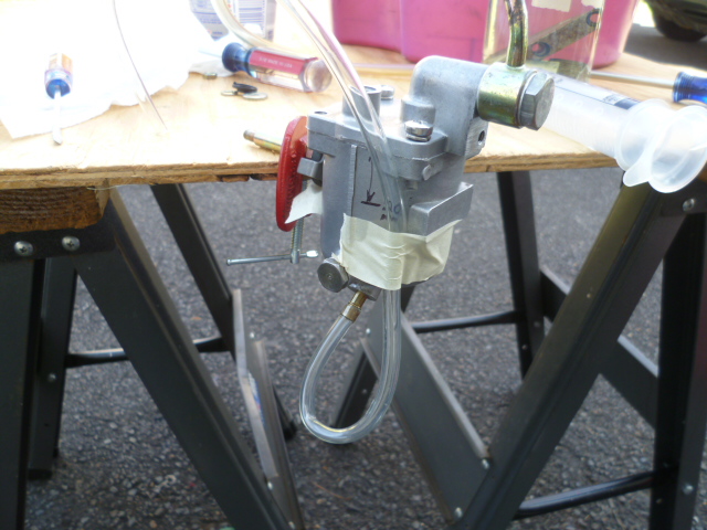
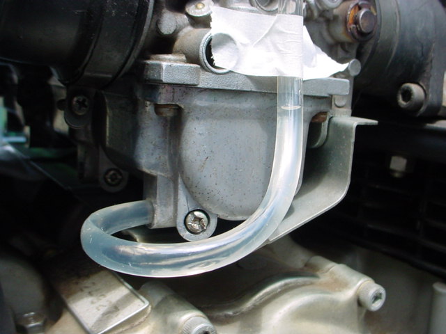
Thanks Steve mudkip777, Basically, the process goes like this... Put the carbs together and put them on the car. Everything connected per normal. Then pull the black rubber tube off the nipple on the bottom of the float bowl and temporarily connect up a length of clear plastic tubing in it's place. Position the clear tube like the pics in that thread and then run the fuel pump. In your case, that probably means cranking the engine to make the mechanical pump deliver fuel. The fuel level the develops in the bowl (and hence the clear tube) should meet the spec in the service manual. I would suggest pulling the plugs and make sure you have a fully charged battery. It could take some cranking to get fuel to the bowls. That's the clear tube method in a nutshell. Details left to the studied reader. Here's a couple related pics that might help Separated from the rest of the carb, but here's a 240 bowl: And here's a different carb, but the concept is the same:
-
There are some pics on the site that show how to check the float bowl level using a clear piece or plastic tubing. I'll dig around a little and see if I can find them, but someone else will probably find them faster.
-
Oh, OK. I saw the note about struggling above 4K and I was attributing that to other stuff that would be dealt with later. So it sounds like you might have multiple things going on. Let's back up a little... Have you run a float level test using a clear tube to verify that the bowl levels are correct? If not, I would start there.
-
I'm not really concerned by the compression test results. They're all consistent, but a little low. Sounds to me like it's an old Z engine in typical condition. No problem. As for your carb issues... It's all in the adjustment of the carbs. The front carb has no vacuum at idle because it's all the way closed shut. And when it's all the way closed, it doesn't contribute anything to the running of the engine. You're idling completely on the rear carb. Once you get off idle and the linkage opens the front carb, it runs off both carbs and you're OK. But at idle, the front carb butterfly is adjusted completely shut and that carb isn't doing anything. Bottom line? Close the rear carb some and open the front. Adjust them so both carbs are doing something, even at idle.
-
If you had one carb completely off, all six cylinders had a pretty clear path direct to atmosphere. Three of them (obviously) direct, and the other three almost as good to atmosphere through the balance tube. Point is... I don't think you have to run the test again simply with the throttle held open. I think your previous test already took care of that.
-
Sending you a PM about the tach. ☺️
-
Haha!!
-
"Acid solution containing Hydrofluoric acid, Sulfuric acid, and Nonylphenoxy Ethoxy Ethanol Have a 0.13% solution of zepharin chloride solution on hand" Yikes. For those who don't know anything about hydrofluoric... If I remember correctly, the zepharin chloride is an emergency measure to give it a calcium target that it likes better than the calcium in your body. Like your bones. Classic tradeoff between safety and effectiveness. That stuff probably works great.
-
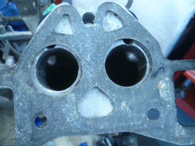
Roger that. Figured there was an easy answer. This issue is fresh in my mind as I've been helping a local guy with his Z and that was one of the issues with his motor. He was running uber-lean for many reasons, and one of them was a mismatch between gasket design and fuel delivery design. He didn't do it, but his motor came to him with the wrong gasket style. Here's a pic looking into the intake manifold while holding the gasket in place. The gasket pretty much blocks off the injector holes completely. His injectors were spraying into a closed door:
-
-
I will take a look to see if I have one of those switches. If not, I'm assuming the aftermarket add-on you have installed (functionally) does the same thing? What the stock switch does is connects the blue/white to ground any time the switch is in any position other than OFF. Your switch may not do the exact same thing electrically, but functionally within the system, it should serve the same function (to turn the compressor off unless the fan is spinning).
-
And I had the pleasure of spending significant time with you at both. Here's to hoping we can do that again at a future event!
-
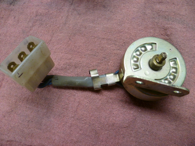
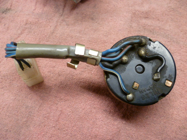
Thinking about it for another second though, there is one detail that bears mention... The "Fan is not in the OFF position" signal is built into the four speed switch that came with the A/C cars. Since your car did not come with A/C and has the three speed switch, you need that auxiliary aftermarket installed switch. Here's a couple pics of the four speed switch:
-
Yes, the resistor is different. You see..... The non-A/C cars (like yours) have three fan speeds while the A/C equipped cars came with FOUR fan speeds: But the top speed bypasses the resistor in both cases so the highest speed is the same. Point is... Yes, the resistors are different, but really doesn't matter for what you're doing.

-
I assume the switch responding to the fan position disables the A/C it the fan is in the off position (so you don't slug the compressor). And the other switch probably cycles the compressor based on the temp of the air through the evaporator. I'm pretty sure you knew all that already, so I guess I'm not sure what the question was?
-
I'd love that. Toronto was even close enough that I drove my Z. If I get to Tampa, I'm pretty sure I won't be driving.
-
I'm not sure which was worse... Austin, Atlanta, or baking in a 130 degree Quonset hut in Memphis!!!?

-
Well I know it's in good hands now. The area that would worry me the most would be issues lurking in the body/paint category. I'm comfortable everywhere else on the car, but not in that area.
-
Why didn't you just switch the struts to the other side? Wow. Pistons? Really? I'm assuming that was not done by the current owner, right? You're not outing him here on the forum are you?
-
Actually looking at the second page of the instructions... That pic is the correct orientation for the NON-Z car applications (like the 510, 610, etc). So it's actually correct for some applications, but not the Z.
-
I think the parts are designed "OK". The real mess-up is this pic: That pic has the parts assembled incorrectly. It has the locations and orientations of the plastic bushing and the aluminum cup backwards. And it also doesn't show the original OEM required rubber bushing on the rear side of the mounting hole in the frame. You see... Never shown in the pics is the original big rubber bushing on the back side of the T/C rod before you install the washer(s) and nut. They mention it in the instructions, but the wording is really confusing. So that said... If you turn the aluminum cup around and put it on first, then that cup is stationary with respect to the T/C rod shaft (meaning that the hole in the middle is just fine to be a tight fit on the rod). And then the oversized tapered hole on the plastic bushing is where the rod wobbles around inside. So yes, the pivot point will be moved out away from the frame hole, but the rest of it looks reasonably designed conceptually. No evaluation of materials used or clearances involved, but at least the concept works. Compression is hard plastic. Tension is soft rubber. Kinda like using poly up front and rubber in the back.
-
Hop, skip, and a jump for you!!
-
Yup. Sorry to be the bearer of bad news. Good luck with the project!
-
I cut out the accordion section for the pic, but I eventually fashioned a different piece to take it's place. It's not pretty, but it works. Here's a pic pulled over from that other thread of another guys solution: