Captain Obvious
Free Member
-
Joined
-
Last visited
Everything posted by Captain Obvious
-
 Weird. I wonder why they discontinued the warm white. Glad I got mine when I did. Wish I had bought more than one. I don't have a 4-LED in warm white, so I can't directly answer the question. I have a 4-emitter in cool white and I don't like it. Both because it's cool white, and because it wasn't bright enough. I assume you dug around on the web to see if there were other places to buy the 6-emitter in warm white?
 -
I did the internally regulated alternator upgrade a little while ago, and everything is fine with the exception of one ignorable low priority issue. Such a small issue that I wouldn't consider it a "problem", but more of a "curiosity" and it highlights some (what I think is) interesting alternator trivia. Goes like this... Sometimes when I first start my car and the RPMs are (cold) low right after I start it, the alternator doesn't spin fast enough to snap into regulation.This is evidenced by the charge lamp being lit and the voltage indicated by the voltmeter. I can give it a little gas to pull the car out of the garage and just that little bit of RPM increase is enough to get it to snap into regulation and from that point forward everything is fine... Charge lamp goes out and the voltmeter shows that the alternator is outputting a healthy 14ish voltage. The way the system is supposed to work is that the alternator pulls a small current (bootstrap) through the charge lamp and this current energizes the field coils until the alternator is spinning fast enough to produce field coil current by itself. Once the alternator is spinning fast enough to produce it's own internally generated field coil energy, it snaps into regulation and the bootstrap current flowing through the charge lamp stops and the lamp goes out. On my car, I sometimes need to increase the RPM's a tiny bit in order for this to happen. I'm not going to do anything about it, but I COULD also fix this by increasing the amount of bootstrap current. So... If I'm not planning to do anything about it, then why am I bringing it up in the first place? Because I noticed an oddity on the 78 wiring diagram that would support my theories and potentially fix the issue. In the Engine Electrical section of the 78 FSM, they describe how the system works (page EE-13). And on that page (and the following page) there is a circuit diagram of the system that includes a resistor in parallel with the charge lamp. This resistor could provide additional bootstrap current to add to what is pulled through the charge lamp: This mystery resistor is not shown on the complete car wiring diagram, nor on any of the circuit detailed descriptions in the Body Electrical section. Does anyone know if this resistor truly exists? If so, what's the value? Is it built INTO the voltmeter gauge, or is it buried in a wiring harness somewhere? Does it plug in like the tach resistor does? I simply can't sleep at night not knowing!!
-
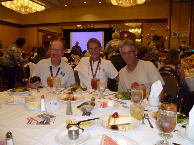
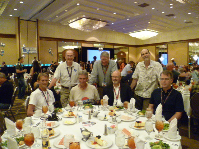
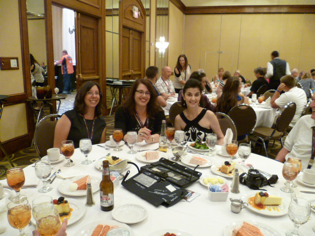
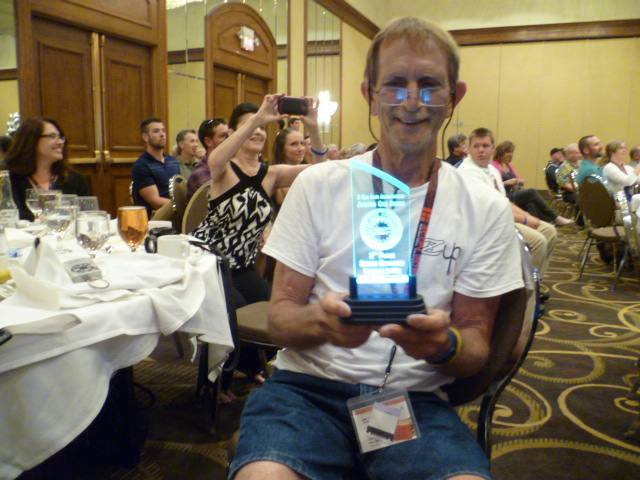
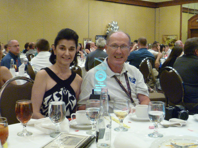
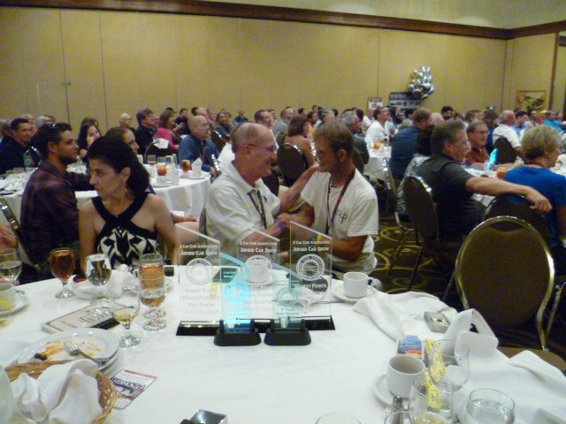
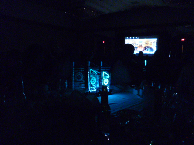
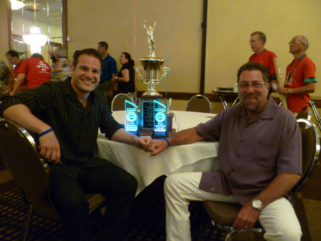
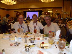
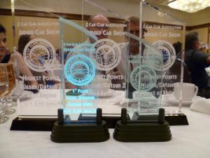
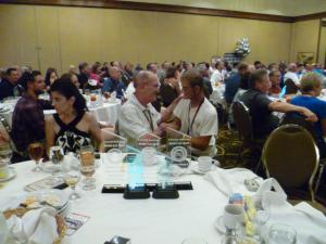
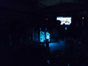
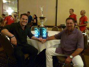
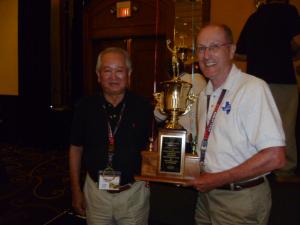
Jim3 A lot of our motley crew. Jim, Jim, Jim, Steve, Bryan, Bruce, Philip. The better halves So proud! Jim and Vicky Jim2 hiding behind so many trophies! jim2 Glowing trophies Mike W and Alex Gold winner and Mr. M


-
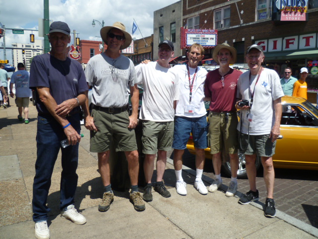
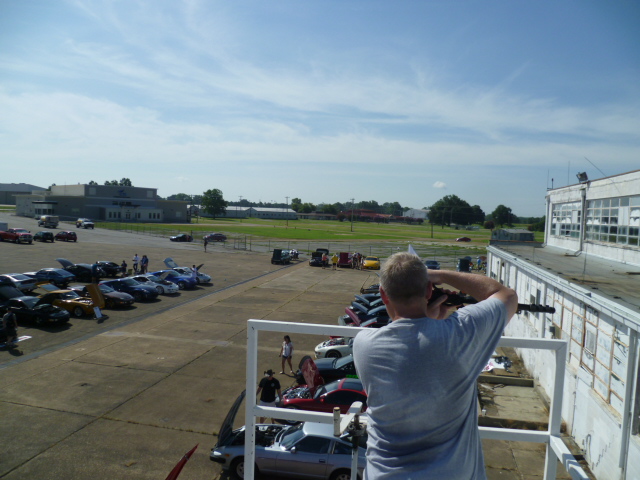
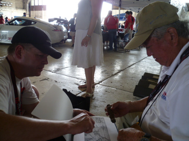
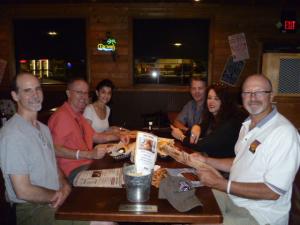
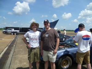
Here's my shots from the event. Flight to Memphis Dinner on Thursday Eve Bunch of us on Beale Street. Jim, Charles, Philip, Jim, Bruce, Jim Unicornicopia Taking a picture of Steve taking a picture from on top of the scaffold platform Me sporting my Fiero shirt at the Saturday show with a fellow Fiero enthusiast Philip presenting Mr. M a gift of a section of the first transatlantic communication cable laid between North America and Europe. The thing that looks like a cigar is actually a couple inches of the rusted original cable that's over 100 years old.


-
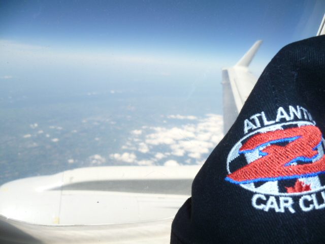
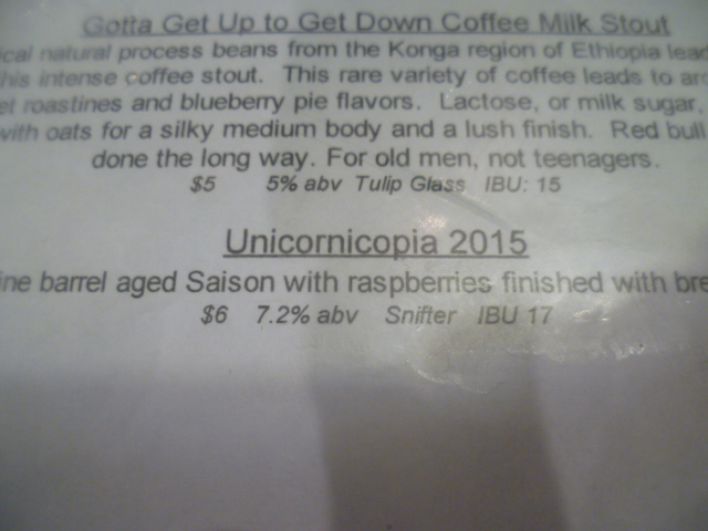
Here's a couple pics from my Zcon adventures. Shot out the plane window while in the air on the way to Memphis. My Atlantic Z Car Club hat so graciously given to me by Blue: : And here's one that I took while I was out with Cliff at one of the brew pubs. This was at Wiseacre Brewing. They said they normally offer a rainbow topping for the Saison, but they had sold out earlier that day: Those are two general pics. I'll put up some more of the ZCon specific shots in the pics thread: http://www.classiczcars.com/topic/51932-some-zcon-pics/
-
Some of my unique experiences? I got to ride in my first series one car. Maybe you saw it? Jim - jfa.series1's car? I think it won a couple awards or something? I failed as Jim's navigator, but in fact, it was actually a ploy to spend more time riding with him, chatting about past lives and technology that was cutting edge at the time, but few would even remember at this point. Thanks Jim! I got to start Cliff's - siteunseen candle burning at both ends with a microbrew tour of Memphis. With horns honking behind him, he pulls his car over to the curb at the end of Beale Street, I pop the passenger door and jump in. We had never met before that... Cliff says "I'm completely lost. I got no idea where we are. Can you get us back to the hotel?" So did the best I could with my limited resources. No nav, no smartphone, and the only map I had was the one I posted earlier with the brewpubs as landmarks. We made it back to the hotel just fine, but we "had" to stop at three of the pubs along the way just to make sure we didn't get "lost". It wasn't that we WANTED to, it was strictly necessity. Thanks Cliff! I got to spend a bunch of time with my buddy Philip - Blue and Mrs. Blue and share my non-tourist philosophy with Mrs. Blue. It turns out that the two of us had completely independently acquired the same targets when it came to food. And I also was learned that my ideas for restaurants was NOT what SteveJ and his wife were ready for. Thanks for indulging me anyway!! Thanks Blue and Steve! I regret that I did not go out on the last night's food and drink expedition with Mike W. and crew. I unfortunately had an early flight the next morning and couldn't stay out partying till 3:30 in the morning as was promised . I would have loved to go, but really needed to be sharp the next day! Thanks Mike! I got to have a wonderful small group conversation and late night drink with Mr. M, one of his companions and Jim - S30Driver. I was trying to ask questions that he doesn't get asked frequently and it was great having Jim there to participate. Thanks Jim! I got to meet my long lost brother Jim - Zup who's got a whole lot of experiences and perspectives on the world different than the average bear and I'm glad you're able to share them and stay sane. Thanks Jim! I've got some (what I consider) interesting pics I took along the way and I'll get them posted soon. So thanks all for the wonderful experiences and I'll include more when I can!
-
Ok... I'm home!! Completed my combination whirlwind tour of Memphis and Washington DC. Had a fantastic time at Zcon 2015!! There was a healthy contingent of ClassicZ forum members there and the chatter here on the forum leading up to the show allowed us to find each other once we got to the show. There were ten or so of us that hung together during the event and I'm very glad we were able to do that. Prior to this event, very few of us had ever met face to face and because of that, you never really know what to expect when you do meet in person. Well, I have to say that my expectations were exceeded in every way and the ClassicZ people I met were some of the nicest, friendliest folks I've ever met. I want to thank everyone that indulged me and went along with any of my hair brained ideas. Everything from carting my sorry asse to and from events and venues to climbing rickety structures for pictures to getting out of their comfort zones in sketchy neighborhoods. I'm honored to have spent the time with you guys, honored to be part of the glove box signing, and thrilled to have had the opportunity to spend time together with the crew. Blue, Brianpilati, Jfaseries1, Mikew, Patcon, S30Driver, Siteunseen, Stevej, Zup... So to all you guys and gals helped make this a wonderful experience, thanks so much!! Hope I didn't inadvertently leave anyone out!!
-
In DC. Stop Very little Internet. Stop Unicorn out late partying. Stop Will respond more soon. Stop
-
Magnetism is not a completely reliable way to determine stainless from non-stainless as many stainless grades are magnetic. So if it's NOT magnetic, it has a good chance it's stainless, but if it's magnetic, you still don't know for sure.
-
Woot woot. After Jim went to bed and you and Jim were tearing up the roads at midnight, Jim and I were bending Mr. M's ear at the bar. I can only hope he enjoyed the conversation remotely as much as I did.
-
It was great meeting the crew from ClassicZ and thanks all for putting up with me!! I've got some pics from the event that I'll post when I can, but in my currently hamstrung technological state I can't do it from here. I had a great time hanging out and will be headed out on the hotel shuttle shortly. Congrats to all the trophy winners!
-
A bunch of us ClassicZ folks got together tonight for some food. I have some pics from the event, but can't upload from here. Tomorrow morning, SteveJ has promised me grits!! Can't wait!!
-
Yeah, seriously... When you say "everybody's here", does that mean you're in Memphis? That would be awesome! This is my last correspondence before I pack it up in preparation for the trip. Next time I'm looking at a screen again (other than my flip phone), I should be at the Hilton in Memphis myself.
-
Zed, You're over a month late. We squelched that version of "hookup" at at the very beginning of the thread on page 1.
-
Steve, That's a great offer and would be happy to take you up on that even if there is a shuttle! Only possible complication is that back on the bottom of page 2, I offered to help Jim Arnett load his car onto his trailer after the show so he had time to get to the people's choice show and still make it back for the banquet. Jim was up in the air at that time if he was going to go to the Saturday show or not, but if he does want to take his Z to the show, I might have to bug out a little early to help out with the loading. Play it by ear I guess?
-
I just took a fresh look at the event schedule: http://zccazconvention.com/conventions/2015/?page_id=12 But there is no mention about a shuttle from the hotel to the people's choice show in Millington on Saturday. Can one of you kind folks who is already at the event please clear that up with one of the organizers? Without a shuttle, people there without a car (like me) will have to skip the Saturday show or figure out some alternate transportation.
-
That's a bummer. Only suggestions I can offer are to make sure all the mating surfaces are very clean and rust free and use some silicone lube. Rust on the faces of the involved surfaces not only takes up room that you need, but it also won't slide as easy as a clean cast iron surface. Unlike the stock rubber bushings, the poly bushings need to slide against the faces of the strut casting. The sliding surfaces need to be clean and lubed. Do you think the poly parts were made properly or is the shoulder too thick?
-
Here's my overview map:
-
Great pics. I'll be there soon. Don't use up all the fun before I get there!
-
Reverse engineer what's inside the cans using some sort of sniffer? Not a chance. In the past, I have on a few occasions, ground down through component encapsulation to expose the silicon inside and do a little reverse engineering and failure analysis. On something extremely simple (like a FET) you can make out what's what. But on something more complicated than that, you really need a roadmap. The reverse engineering I did on stuff more complicated than that included design documentation from an ASIC house that had designed a chip for the company I was working for. And even with that documentation in hand, I couldn't get too far from the pins before I got lost in the topography. With 1970's technology, the chips should be less complex than today's higher density CMOS stuff, but I'm with Fastwoman... Beyond my pay grade. Maybe someone who designs silicon all day could reverse engineer under a microscope, but that's not me. I believe that with scopes and meters in hand and enough reverse engineering at the board level, I think it might be conceivable to determine what the cans DO (black box) and infer what's inside. I'd be happy to take a shot at that if someone wants to send me the schematic for the ECU.
-
Me three. Is there anything someone (like me) can do from a distance to help?
-
Haha!! Yeah, that film is one of my all time favorites as well, and I agree with you about Escape from LA. I wouldn't be surprised if someone actually made a version of that car after seeing the movie. A little scared, but not surprised.
-
Yeah, I'm just tossing out ideas. Not necessarily GOOD ideas... I can't really come up with anything definitive that would cause overadjusting of the rear brake. So what happens if the cylinder doesn't slide properly on the backing plate or if it's not centered properly between the two when you put the drum on? I know the whole thing is supposed to center properly the first time you hit the brakes, but what if... What if it doesn't? Is it possible that the piston extends and pushes the one shoe out too far against the drum. And is it also possible that the shoe itself pushes against the parking brake lever causing the ratchet arm to give the wheel a notch or two? Hit your brakes fifty times and you've got fifty teeth? I don't like that floating cylinder design and I'm just glad that my 77 doesn't have that style. I had enough of the early style with my 74. Maybe just keep an eye on it and hopefully it just won't happen again?
-
Neo Classic? How about chandeliers and a disco ball?
-
Haha!! I say we take off and nuke the entire site from orbit. It's the only way to be sure.