Captain Obvious
Free Member
-
Joined
-
Last visited
Everything posted by Captain Obvious
-
 The best paint option I've found is different than what the general consensus uses. Bottom line? Rust-Oleum 261413 Metallic Carbon Mist. Top coat with Krylon Colormax 53530 Flat Clear. Bunch of detail here: https://www.classiczcars.com/forums/topic/67836-rear-tail-light-panels/#comment-645395 I know I'm swimming upstream against the other recommendations for the BFM0360 Ford Dark Shadow Gray, but if you're willing to entertain other options, I recommend the Metallic Carbon Mist. I also like the flat top carbs.
 -
Maybe it's just me, but there's no way I would put a water based liquid in there. Yes, with antifreeze, it won't freeze, but there's just no way. I'd use something petroleum based. Is there a reason you didn't use oil?
-
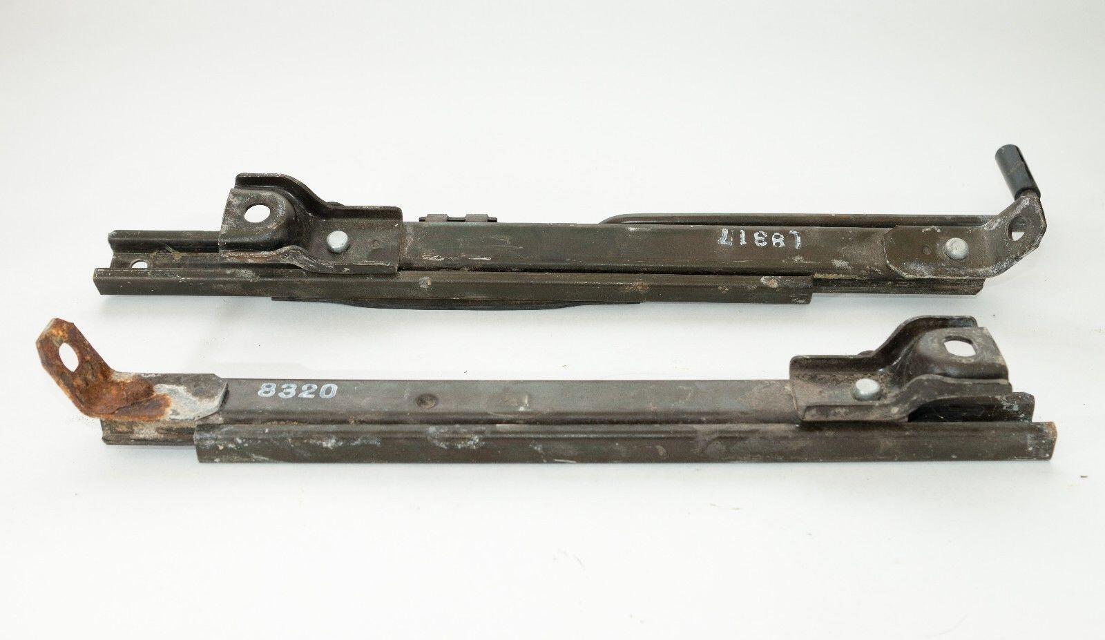
There are at least three different varieties of the seat tracks over the years. The final version (what you have) was used in 77-78. The easiest way to notice the difference at quick glance (for me anyway) is the angled front tabs. Here's a pic where you can see the angled tabs. This is what you need for your 77: As for the ZX seat tracks, I have no idea if they are the same. Can you post a couple pics of the ZX rails?

-
That switch should be closed any time there is a key in the lock regardless of what position the lock is in. Should not matter whether the lock is in the OFF, ACC, On, etc. And a little late with the pics, but...


-
A reading from the Book Of McMaster: High-Load Oil-Embedded Sleeve Bearings Increased iron content makes these bearings stronger and more resistant to shock loads than standard oil-embedded bearings; however they operate at lower speeds. Startup friction causes them to release a thin layer of oil on the bearing’s surface. Color is silver because of the iron. These bearings are also magnetic due to the high iron content. So I bet they are still oil impregnated bronze, but the high load variety with enough iron to be magnetic.
-
I made a pilot bushing remover tool many moons ago (many). Probably made it for my Z at the time. Man, have I gotten a lot better at making things since then. I probably still have it and if I can find it, I'll post a pic.
-
I've toyed with this idea in the past and if I come up with a simple and elegant solution, I'll let you know. And I'm sure you'll do the same. I've messed around with one of these little timer modules, and while it's overkill, it would work. Under ten bucks off ebay. One shot or continuous output. Programmable on time or off time. On pulse, or off pulse. Moore's Law. Throw transistors at it. Example ebay availability: https://www.ebay.com/itm/334738777145?hash=item4deffc6439:g:WuoAAOSwc4FdeKyz&amdata=enc%3AAQAIAAAA4G9hgNdMy2ONBPE71Z3gGq3qzRvQaK%2BWxXTNH9UcLyqdQOnalj%2FTC7kXod2gRdFTsLiWo6%2Bw1CPybhOzekN701%2F%2BflwUhMM%2FPFwIW2dw8osWQx9N5Y%2Bzkpow7cdoPTmHLYpoPfIk%2FRFNVEEBRJsPYuXmY4ugTqfGWpl7Ec4CWDHRZSS741ZOWEezeh8wGXqgvZyp08MiOeeLydivakdTYNtrBhLn%2F0TIsZKVjDUwYSL53goggea6rIRywsYDHcrtu5vM73hwhkBkbaBkKp%2FbkO65VxtF9cypNMy2%2BfSyOCw%2B|tkp%3ABFBMrtrs_Oli
-
I'm a little confused... Isn't the Hi/Lo beam switch SUPPOSED to toggle between the two positions? I'm thinking if that's what it's doing, that's what you want. What am I missing?
-
I've had problems with the stock pump priming sometimes. Usually will prime, but sometimes won't. And if you think about the way it works, it's not surprising. I'm thinking that the insides of the pump and the impeller bits are not a gas tight fit. It pumps the fuel because of the relative incompressability of the liquid and the fact that even though there would be some losses between the parts, the majority of the fuel will be moved from one spot to another. Not necessarily the same thing will happen with a gas.

-
Your response got here just before mine, but the summary of my post is that the car parts manual lists three different sash part numbers*. 80200-N3400 up to 7506 80200-N4500 from 7507 to 7607 And it supersedes 80200-N3400 80200-N4400 from 7608 to the end of the run. And it supersedes 80200-N4500 Based on that, and your pics, it's not a straightforward swap. * For the 260-280 cars. The 240 used a different part number.
-
I'm no engine builder expert, but I've always installed the bushing to even with the bottom of the chamfer like you and Patcon. And I greased them a little as well. With the same stuff I put on the throw out bearing collar. High moly I believe? About installing... Block of wood and a mallet to get it started. Continuing like that until flush with the flywheel surface, and then tapped "gently" with an appropriately sized dowel (wood or plastic) and aforementioned mallet to get it down the the bottom of the chamfer.
-
I will take a look at the trim mounting scheme and take a couple pics of the later design. I don't know if the 77-78 design will fit other years, but maybe we can figure it out. I do know that the 77-78 doors are very different in a lot of ways, but I'm not sure if the window trim is one of them.
-
Excellent. And in theory, that peel-n-seal stuff is removable enough that if you ever do have to pull the tail lights out again for anything, it will let go easy (as designed) and you won't have to put a lot of stress on the plastic light housings. Glad you got the fume issue under control!
-
So there was an intermittent connection in the "T" connection at the back of the alternator? You fixed that and you're charging system is all good now? Excellent!!
-
Thinking about it some more, I think this could work if you did it well. Some threaded aluminum rod screwed into the holes and loctited (red) in place. Then file flush and put in your new mounting holes. If you could cut the threads yourself on a lathe, you could make the threaded rod a tight class of thread fit which would make matters better. The new holes will be split about 50/50 between the old bolt hole and virgin material. I think red threadlock would work, at least for a proof of concept. and once you get the throttle body installed, it's not like anything will be able to move anymore. I'd give that a try over using a plastic 3D-printed adapter.
-
-
Yeah, really nothing to lose. Just soak them again in the citric and see what happens. I had some black staining on certain parts, but it was the higher carbon stuff. Things like that pulley worked fine, but I did find that the original zinc (assuming that's was actually going on) was thicker in some areas than others and took longer to come off.
-
Yeah, this is a situation where wings flapping is not what you want.
-
From my limited experience, I think that is leftover zinc from the original plating. I didn't look into it any from a chemistry standpoint, but when I was doing the citric acid cleaning, it seemed like the yellow chromate came off quickly (if there actually was any remaining), and then the zinc came off next at about the same rate at which light rust came off. So I'm thinking that if you would put those parts back into a citric acid bath again (maybe a fresh (warm-to-hot?) bath), I think those large darker patches might come off and leave you with a homogeneous surface.
-
There are four screws at the upper front of the console. Those screws (two on each side) go into the radio bracket. That bracket does not attach to anything else, so it does not anchor the console to the car in any way, but it does provide support for the two front "wings" so they don't flop around. The other two screws lower than that (one on each side) actually hold the console in place. Those two go through the console and screw into the #10 bracket, which is attached to the transmission tunnel.
-
When you did it a second time, did you weld both sides of the pin, or just the far side from the cable? Also, did you consider silver brazing the cable into the pin? I think I would have tried that.
-
-
I'm a little disappointed that there wasn't the obligatory "Hey Y'all, watch this!" at the beginning.
-
-
Wooo Hooo!!!