


Captain Obvious
Free Member
-
Joined
-
Last visited
Everything posted by Captain Obvious
-
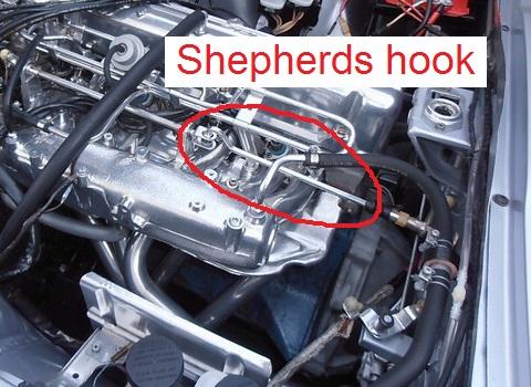
 That pic threw me at first as well. But if you blow it up to full size and look carefully just to the right of injector connector #3, you can see the cut ends of the wires from the rear bank of three. The way they are laying in the pic makes it look like it's a full harness of six (as it was intended), but it's actually two smaller harnesses of three injectors each. And as for the AAR, that's probably red 5/8 heater hose. The original hose turned to rock and crumbled to dust, so they replaced it with some heater hose of similar size. Not that I've ever done such a thing....
 -
This thread seems to indicate that it wasn't just the 77 and 78 cars that had that snorkel:: https://www.classiczcars.com/forums/topic/60231-76-280z-complete-fuel-injection-sys-more/
-
I'm no carb expert, but that is my contention. I do not believe the absolute fuel level is as critical as many people believe it to be It is my contention that the majority of the pressure drop occurs at the needle restriction, and not much caused by the different height of the fuel. What is the psi reading at the bottom of a 2 mm tall column of fuel?
-
I've got one just like that. 2.0 stamped on the side, and the Hitachi logo. Just one in a box of assorted round top parts. I've got way more flat top parts than I do round top. Surprised?
-
LOL! I go off-line for a couple days and come back to this? I appreciate the accolades, but I fear you guys give me waaaaay too much credit! Blind squirrel and all that...
-
That doesn't look like it got wet to me. Just looks like old non-sealed electronics IMHO. And if it's dead, I wouldn't bother trying to troubleshoot. They're easy enough to find used still working, and failing that, there are aftermarket options. How's this for a litmus test... Even I wouldn't spend a lot of time trying to fix one of those. And the reason your wipers work slow is probably a completely mechanical issue. Crud and rust in the linkage, especially where the wiper stalks poke out of the cowl area up to the glass.
-
I measured the overall height at about 21.5 inches (+/- .25 inch for parallax error). I uploaded a couple pics. Measuring the height: Here it is snug as a bug in the back of my 77: And (as embarrassing as it is...) here's a pic of it on the car when I did a short test run to make sure it actually worked:
-
Perfect. That's exactly what you're looking for. Good luck with the Toyota brakes. I don't know anything at all about them.
-
I agree with the above. Sad to see such an iconic Z looking like that. OK... Experiment over. Rust works in Canada. Now build yourself a bigger garage, eh?
-
I was (half) joking about it coming back again in the future. It's an old engineering adage taught to me by one of my mentors that if you have not positively confirmed the root cause of the failure, then it's likely to come back again. Here's to hoping that's not the case here!
-
Great! So you confirmed that leaving the distance piece out won't provide the proper bearing preload? About the grease seal rubbing, we did the same thing here with the first one. Didn't press it in far enough and it was rubbing some against the back of the yoke. Easy fix. So were you able to ever get confirming distance measurements off the second hub before you put it together? Or once you saw that everything was "B" length, you just went for it? In any event, I'm glad you got them together and feeling good. I bet you're happy that's over!
-
You are absolutely right!! I thought of it this afternoon while walking around at the junkyard, but couldn't post until now. Everything You Always Wanted To Know About Sex But Were Afraid To Ask Remember Tony Randall and Burt Reynolds in that? https://www.youtube.com/watch?v=nM3fglmaRrA
-
Here's the summary. Do any of you 280 guys who converted to triples or cable linkage have this part laying around left over? Here's a pic of the part needed. This part of the linkage off a 280Z:
-
My local Nissan dealer seems as though they couldn't care less whether I exist or not. At this point, I try to never go in there. No discount off full retail, and no understanding that I sometimes might even know what I'm talking about.
-
I think that is OSHA required safety gear while you are in the Orgasmatron:
-
If connected and working properly, the system is supposed to store the vapors in the can with the engine off, and then pull them out of the can and burn them when the engine is running. In theory, the carbon canister is supposed to be a temporary holding vessel and you are supposed to empty it ("purge") when you run the engine. However, I wouldn't be surprised to learn that the emptying process is never 100% complete and it could eventually saturate over the years. I haven't looked into it, but that wouldn't surprise me. Is that what happens?
-
@Patcon Over in this completely unrelated thread: https://www.classiczcars.com/forums/topic/60181-cleaning-the-filter-on-the-carbon-canister/ The subject of activated carbon came up, and as a result, I found this on Wikipedia: "Industrial application: One major industrial application involves use of activated carbon in metal finishing for purification of electroplating solutions. For example, it is a main purification technique for removing organic impurities from bright nickel plating solutions. A variety of organic chemicals are added to plating solutions for improving their deposit qualities and for enhancing properties like brightness, smoothness, ductility, etc. Due to passage of direct current and electrolytic reactions of anodic oxidation and cathodic reduction, organic additives generate unwanted breakdown products in solution. Their excessive build up can adversely affect plating quality and physical properties of deposited metal. Activated carbon treatment removes such impurities and restores plating performance to the desired level." Here's the URL for the page: https://en.wikipedia.org/wiki/Activated_carbon I never knew any of that, and filtering used solution through activated charcoal filter might help with what you're doing?
-
The turn signals say 240, but those are clearly 280 bumpers!!
-
Oh yeah... And the serious part. Activated charcoal is funky stuff and I'm not sure how it would take to being completely doused with water. What makes it so cool is the amazingly gigantic amount of surface area it has for it's size, and I'm not sure how well it would dry out. I would shop-vac as much of the crud as you can off the bottom, put a new filter on it, and use it.
-
Nailed it. "Told my girl I have to forget her Rather buy me a new carburettor."
-
Queen wrote a song about this.
-
And forgot... I think dripping ABS solvent down into that crevice is a really risky move. I think that if it wasn't securely glued before you do that, it most certainly will be afterwards!
-
Mice used your old filter to build a nest a very long time ago. AC Delco claims to have a replacement available on Rockauto for $1.48. Look for ACDELCO part number A478C. I've heard that Rockauto is no fun in Canada though. Shipping costs are high?
-
"I know, right?" For something so seemingly simple and stupid, it's really a PITA. I did mine while in the car but while the dash was out. And while it isn't as bad as on your back upside down head under the dash, it was no picnic either! You CAN take just the individual contacts out of the connector shells and leave the shells clipped into the white plastic support bracket. What (in the grand scheme of things) is it that you are trying to do?
-
Cool. Here's to hoping the few threads you caught are enough and you don't have to put more work into it. And not that it really matters at this point, but... I don't know if all the clutches work this easy, but I've found that simple gravity bleeding works fine. Maybe one or two pumps at the very end just to make sure all the air is gone, but I've had good success with just letting Sir Isaac Newton do most of the work.


