


Captain Obvious
Free Member
-
Joined
-
Last visited
Everything posted by Captain Obvious
-
 Yes, the carbon monoxide percent is measured with a special meter. It sounds like you're doing pretty good. The only thing that you might still have to investigate is your idle speed and the position of your idle screw. If that screw is all the way down and you're still idling at 1000-1200, it's an indication that you've got vacuum leak(s) somewhere. I suspect it's a bunch of little leaks spread throughout the system. Rubber boots, small cracks in hoses, injector seals, throttle body and intake manifold gasket, etc. However, at this point, if it runs good and doesn't stink, you might consider taking it in for a pre-test so you know what you're dealing with. Who knows... If you've got some small vacuum leaks and you would be running a rich idle without them, maybe they'll cancel each other out and you might even pass.
 -
So infinite resistance across the pick-up coil? If that's the case, then it certainly does sound like your pick-up is dead. Carry on, and sorry for the distraction!
-
Reluctor wheel grinding against the pickup face is never a good thing, but before you convince yourself that the pickup is dead, you need to ditch the "continuity" reading on your meter and use Ohms. The spec from the FSM is 720 Ohms. I don't know if that's high enough of a resistance that the "continuity" scale on your meter might not pick that up. In other words, the pickup coil could be just fine but resistance of the coil may be high enough that your meter won't consider it a connection (and won't beep on continuity).
-
Cool. Hope that keeps the gremlins away. And if it does come back, think of it as an opportunity to find and put a stake it for good. Haha! So remote electrical troubleshooting over the internets is always questionable. But from here, it really sounds like a poor connection in the main power branch of the car... Battery terminals and cables, starter wiring, fusible links, shunt assembly, some big ground connection near the battery... Something like that. Not the ignition switch. Hoping you already took care of it and you're good to go!
-
Right. One of them (the big one) goes to the starter, and the other one powers the EFI system (and only the EFI system). The rest of the car (everything except the EFI) is powered off the white wire is connected to the other end of that big (+) battery wire down on the starter.* Next time it happens, wiggle stuff around and see if you can pinpoint where the issue is. Battery terminals up on the battery. Other end of the (+) wire down at the starter. Wiggle the fusible links. Wiggle the body ground wire next to the battery below the wiper connector. Happy hunting, and here's hoping you find it. * Want proof? Disconnect that EFI spade connector and then turn the headlights on. They should light up. Then try to start the car. The starter will turn the engine over, but it won't start.
-
Glad you're out of the woods for now but I'm not sure that was really the root cause. I think the corroded connector you found is the fusible link for the EFI system (and only the EFI system). If that's the case, it could account for the car cranking fine but not starting. Corrosion there wouldn't account for the rest of the symptoms you had. I'm thinking that while messing around up by the battery and cleaning that connector, you bumped whatever really WAS causing the issue. Hope not, but it might come back.
-
First thing to try... Clean your battery terminals.
-
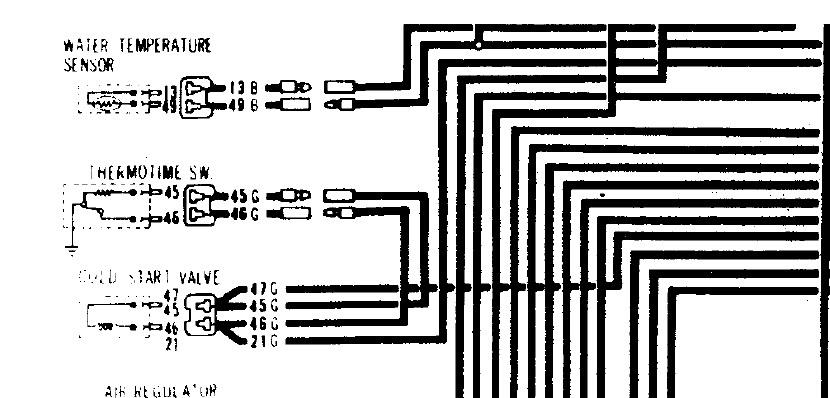
And the point of the snippet I posted is to show the inconclusiveness of the wire colors on the sensor side of the little stub harnesses. The pic Zed Head posted has black for everything in those little harnesses, but the one I posted has black for one sensor and green for the other. That's why I was saying the colors on the main harness seem to be well defined, but on the sensor side, those little foot long harness extensions are ambiguous.
-
I took another look just to make sure I saw what I saw... Here's a snippet from another FSM. Supposedly for a 77. "B" is black and "G" is green:
-
Yeah, I forced some of that stuff together too and tried to convince myself it was good enough. And then I bough the Yazaki stuff. Haha!! Sorry about the lack of extractor pics. Completely forgot.
-
-
On the main EFI harness, the black wires go to the temp sensor and the green ones go to the thermotime. ON THE MAIN HARNESS. As for the little stub harnesses that connect to the main harness and convert from bullet to EFI style connectors, I'm not positive of the wire colors*. One wiring diagram I have indicates that those same wire colors were continued all the way to the thermostat housing (pair of blacks to the temp sensor and pair of greens to the thermotime), but another FSM diagram I have indicates everything past the bullet connectors is black. So as for the stubs... I'm not so sure. But of course, since they're just a foot long, you can easily verify the connections just by tracing the stubs back to the main harness. * And I can't check my 77 as my stubs have been remade and aren't original colors anymore.
-
THANK you!!! I was beginning to think that nobody got that at all!!
-
I made (surprised?) my own extractor tools for those connectors. I'll take a pic and post next time I'm in the shop. You think the male pins are difficult? Just wait till you try to take one of the female receptacles out! And you're also trying to mate new parts with those? If so, there's nothing from Molex or Tyco that is going to work. Everything is the wrong size. You're going to have to spring for the Yazaki originals. I got mine from CycleTerminal >>> http://www.cycleterminal.com/yazaki-ypc.html And note that they have extractor tools for those contacts... Just $58 for the set! I believe Eastern Beaver has these too, but I didn't have enough of an order to warrant overseas shipping. If you're going to put an order in (from either place), let me know and maybe I can add on a little bit. Since you're working with headlights... Are you looking for the big contact too, or just the small one (like the ones you pictured above)?
-
She's a Beauty!!

-
And as you mentioned, you might pass smog the way it is. I don't know the details.
-
Hmmm.... On the fuel injected cars, the only thing that is really split 1-2-3 and 4-5-6 is the ECU. Everything else is pretty much shared evenly between all the cylinders. If you really think you've got an issue that is split like that, you could try swapping a couple of the injector wires. I think some of the wires have enough slack in them that you can move them around. I'm thinking you could swap the wires going to 3 and 4 to see what happens. If you swap 3 - 4 and then find that your sooty plug follows the injector connector, then you might want to look into a different ECU. Clean up those plugs, swap the wires, and drive around for a little bit and then pull the plugs again to see what they look like?
-
Glad to help. And of course, but some of the potential culprits may depend on the year you're working on. For example, (quick look at some of the wiring diagrams indicate that) 75 and 76 have a connector (C-2) between the fuse and the multifunction switch, while 77 and 78 do not. So if you're working on a 75 or 76, that connector may be corroded as well. But basically... Yeah. I would first start by putting a meter on both sides of the fuse and see what happens when you turn the switch on. Both sides should be solid battery voltage regardless of the switch position. And then work your way downstream from there if the problem isn't the fuse itself. Also, I'm assuming the fusible link and wiring to the "high side" of all the fuses is good or you would have mentioned a whole host of other electrical issues. I'm assuming this problem is relatively isolated to the lights. I mean, if you had a problem with the fusible link, it would show up in a whoooooole bunch of other areas as well. If everything else pretty much works, you ought to be able to start at the fuse box and work your way down from there.
-
Excellent. Not that it really matters, but I'm unclear on what Jeff meant by "it was the wires in the distributor", but like I said, doesn't really matter. I'm just glad you're fixed. And looking forward.... I'm gonna be no help whatsoever on any paint questions. Man's got to know his limitations.
-
First of all, I got no problem whatsoever with this: License plate bulbs (two), the remaining marker light, bunch of dash lights, glove box, cigarette lighter, ash tray.... Probably others. All in parallel? I got no problem with a couple Ohms to ground on the G/W. As for the readings you're seeing on the switch... I'm thinking you've got a high impedance connection somewhere upstream in that G/L wire. When the switch is in the OFF position and there is nothing connected to drag the G/L wire down, it floats up to battery voltage and looks good. But as soon as you turn the switch on, all those filaments in parallel will drag that high impedance source to ground. I'm guaranteeing that there IS current flowing. Just not enough for your home wiring style clamp-on meter to detect. So I'm thinking that's the issue. Finding it is a different story. Fuse that looks good, but isn't really? Barely holding on by a tiny sliver of metal inside? End caps that have been overheated and mostly de-soldered themselves? Corrosion on the fuse clips? Corrosion in the headlight switch? (Unlikely because you would have probably seen that while you were messing with the switch). Solder joint on the back of the switch that looks good, but really isn't. (I've never seen you solder. LOL) Anyway, happy hunting.
-
Glad you got it sorted! Enjoy the ride!
-
The only function of that arm on the front is for anchoring one end of the return spring? Seems like they could have put that somewhere else. Is there a center support tower? If there is, maybe on the rear side of that? Maybe at the back between the rearmost tower and the flange for connecting to the shepherd's hook? Does that use a custom adjustable length shepherd's hook?
-
Sure do! And I apologize they are still sitting there like that!!
-
Thanks. I was thinking about doing just that (after I saw your post on your 510 thread). "Test" out the amount of drop before I permanently committed to it. But I still need a pair of struts!
-
What do you mean when you say the pendulum slowly stops? Does the clock seem to work fine for a couple seconds in the normal position, but then over time the pendulum seems to lose amplitude and eventually comes to a stop? Pendulum won't start by itself, but seems to work OK for a little while if you give it a kick-start? I've seen that before. Any chance you can post a video? I'm with Dave... I suspect some long term drift of electrical components.


