My daughter has an assignment and she is struggling to get going at it the right way. Maybe one of you whiz kids could help
"Basically, I am trying to figure out what the Equations of Motion (EOM) for the system are. It is complicated by the fact that we have a moving cart and a massless pendulum. "
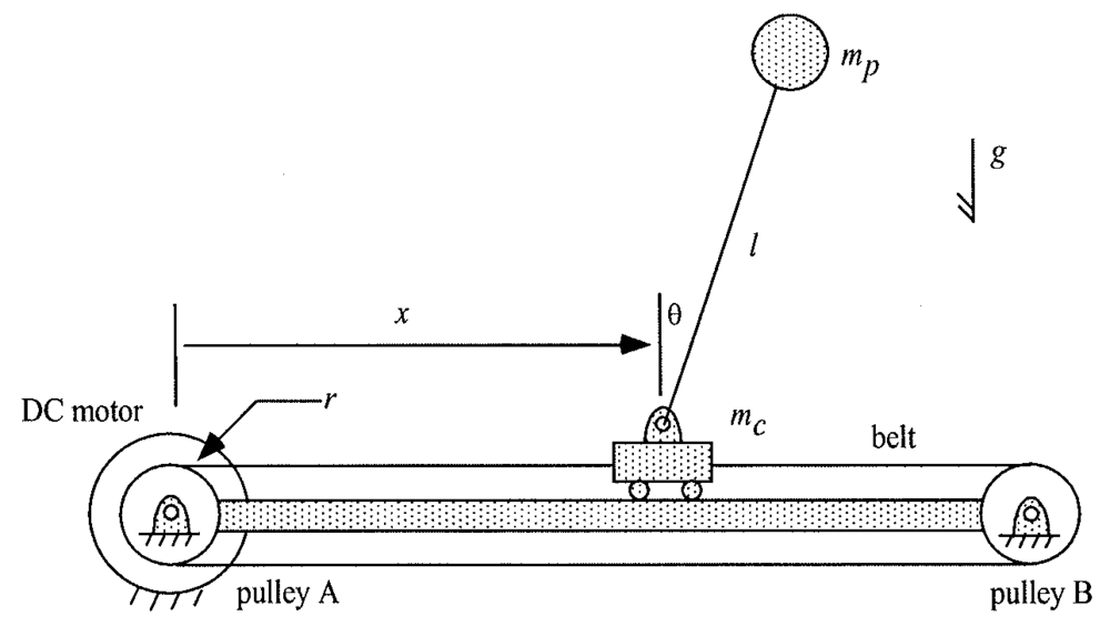
Inverted pendulum is a classic problem in control engineering, as its unstable nature poses a significant challenge to the design and implementation of its controller. The typical configuration of an inverted pendulum system is shown in the figure below.
The moving cart that supports the inverted pendulum is powered by an electric motor through a pulley-belt drive. The rotating bar of the pendulum (mass negligible) supports a metal ball at the top, which can be modeled as a point mass mp. The parameters of the system are as follows:
mp = 300 g; mc = 500 g;
l = 60 cm; r = 2.5 cm.
Additionally, the viscous damping in the cart movement is estimated to be bc = 125 g/sec.
Regarding the instrumentation of the system, the motor shaft rotation angle is measured with a rotary multi-turn potentiometer, with the output of 2V corresponding to each full turn of the shaft. The pendulum angle is measured with a single-turn potentiometer, with ±10V output corresponding to ±160˚ of rotation. Each signal come with 2% of noise. The DC motor in this system has a torque constant of 0.1 N-m/A, and the servo amplifier that drives the motor has a gain of 0.5A per volt of command signal. To simplify the analysis, assume that saturation of the amplifier and motor can be neglected.
2
Controller Design Goals
To prevent the inverted pendulum from falling over, the pendulum rotation angle θ should be stabilized to the equilibrium of zero degree. Additionally, due to the cart’s limited range of motion, the cart movement should be stabilized and controllable. Furthermore, the system should be sufficiently robust against disturbances (e.g., a horizontal impulse force).
As the basis of the controller design, the complete dynamic model of the system should be derived. The model of the plant takes the servo amplifier command (in the unit of V) as the input, and its outputs are the cart position/velocity and the pendulum angular position/velocity (note that only positions are physically measured with potentiometers). In your derivation, model all the dynamic effects without simplification, and obtain the complete state-space dynamic model first. It should be nonlinear. For the controller simulation, this nonlinear model should be implemented directly (without linearization) in the Matlab Simulink to represent the physical system (“plant”). Subsequently, in the controller design, the model can be linearized such that the linear control techniques can be applied.
Two types of control approaches should be investigated, including the classical control (PD or lead compensator) and the modern control approach (full-state feedback).
(1) For the classical control method, the single output of the system should be the cart position (NOT the pendulum angular position). If such method is unable to accomplish the design goal, detailed derivation should be presented to support your conclusion.
(2) For the modern control method, both cart position and pendulum angular position should be controlled. Use the pole placement technique to design the controller.
The controllers should be simulated to quantify its performance. As the references (set points), the desired pendulum angular position is always zero degree (i.e., vertical), and step/ sinusoidal commands should be used for the desired cart position. Furthermore, a horizontal pulse force should be applied to the tip of the pendulum to test and quantify the controller’s robustness, and the maximum value of the force that can be accommodated by your controller should be included in the project report.
Deliverables
This is a group project, with two to three students in each group. The grades will be assigned based on a controller presentation/demonstration (20%), and a project report (80%).
The controller presentation/demonstration will be conducted during the last week of class. Each group will give a 5-minute presentation (2 slides) to summarize the controller design, and demonstrate the controller in Simulink. The controller should be encapsulated into a two-input-single-output subsystem, and combined with the standard plant model (provided by the instructor) for the demonstration.
The project report is due April 26, 2019. Scan or convert your report into a single, colored pdf file (less than 10 MB) and submit it through Blackboard (a group assignment will be created for this purpose). No other files should be uploaded. The following contents are expected in the report (the contents should be arranged in the order shown below):
3
1. A short transmittal letter briefly describing the contributions of each group member, not to exceed one page. This letter should be dated and signed by all group members. (10%)
2. A short description of the project, not to exceed one page using 12 point Times font, minimum 1.5 line spacing, and 1 inch margins all around (minimum). This description should provide an overview of the results obtained in the project, including the system model, the controller design, as well as the simulation results. (10%)
3. System modeling analysis and results. All relevant equations and diagrams should be included. (15%)
4. Control design analysis and results. All details should be presented, including the figures and Matlab scripts. (25%)
5. Simulation results. Simulate the responses to the following commands in cart position: i) a commanded 10 cm step; and ii) 10 cm amplitude sinusoidal commands at 0.25/0.5/1.0 Hz frequencies. Additionally, simulate the system response to an impulse force applied to the tip of the pendulum. Gradually increase the force magnitude and find the maximum value that can be accommodated. Plot the responses of all four states, and also plot the motor torque required. For the sinusoidal tracking, your plots should capture 3 cycles of the desired cart command. Include a discussion on the simulation results, especially on the tracking performances at the different frequencies and the controller’s capability in disturbance rejection.


 Subscriber
 Oh, it's five o'clock somewhere!!!