


Namerow
Free Member
-
Joined
-
Last visited
Everything posted by Namerow
-
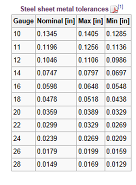
 We'll probably never get a better measurement of the factory floor thickness than that. Closer to 1.1mm than to 1.2mm, so let's call it 1.1mm then. BTW, both 1.1mm and 1.2mm are, according to a modern supplier of rolled sheet steel (Parker Steel / MetricMetal.com), legitimate standard sheet thicknesses for bulk metric rolled sheet... Unfortunately, this is one of those cases where the measured thickness doesn't align very well with American gauge standards... 0.044" places the floor panel right at the lower (thinnest) boundary for 18-gauge. Conversely, the upper (thickest) boundary for 20-gauge is just 0.0389". So, we can consider the factory floor panels to be either thin-ish 18-gauge or way-out-of-spec 20-gauge. We can also say that the floor panels are the same thickness/gauge as the main outer body panels (which, interesting to note, are commonly considered to be "20-gauge" but are, per my notes above, closer to 18-gauge than they are to 20). In the end, 1.1mm is probably the correct representation. Comments welcomed.
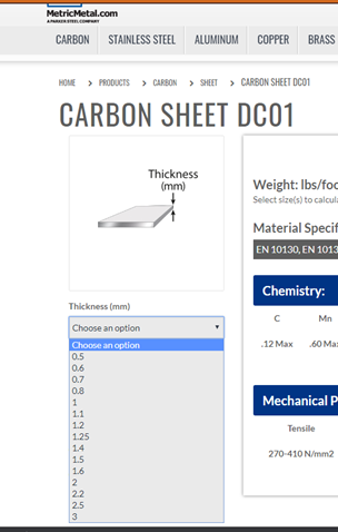
-
A key panel not reported on yet is the floor pan. Anyone? Easy to measure by pulling one of the drain plugs, but requires a vernier set up like CanTechZ's in order to measure properly.
-
Although it's now 30 years old, 'Carroll Smith's Nuts, Bolts, Fasteners and Plumbing Handbook' provides some great insights into fastener technology. Smith was an important part of the Shelby American racing story and a respected member of the American pro racing fabricators' community for many years. He is best known for his 'Prepare to Win' and 'Tune to Win' books, which were racers' bibles in the 1980's.
-
Small-block Chevy? Or maybe it's electric. Front axle looks like at came off a mid-60's AA/Altered Fuel drag racer. Just the thing for you and your friends to arrive in at the local casino.
-
Updated chart... Panel Location Measured Thickness (t) Source Gauge (derived from ‘t’) Gauge (reported) Source Front Apron (engine compartment) 0.032” Jfa.series1 20 20 Grannyknot Tabco repair panels (all) 20 Manufacturer ConverTT Klokkerholm repair panels (rear quarter) 22 ConverTT Thick-gauge panels & pieces (which ones?) 18 2manyZs kmack Lower Front Frame Rail (OE) 0.050” Carl Beck 18 18 ConverTT Lower Front Frame Rail (ZeddFindings) 0.062” Namerow 16 Upper Front Frame Rail (‘horn’) 0.054” Carl Beck ~ 16 Front Valence Panel 0.032” Namerow ~ 20 Front Crossframe 0.076” Namerow ~ 14 Door – outer skin 20 ConverTT Inner Rocker Panel 18 ConverTT Radiator Support 18 + 20 ConverTT
-
Well, it could be a lot worse, you know. In England, they came up with something called the 'British Whitworth' system for fastener threads and that is a standard that defies comprehension (I can hear keyboards in Britain warming right now and I expect that we'll shortly be seeing explanations about why BW is actually the best system in the world ?). Here in Canada, our government decided way back in 1967 that metric was the way of the future and decreed that it would be the national standard from that point forward. Unfortunately, our neighbours to the south didn't completely agree (although large parts of the American industrial community did, including the auto manufacturers). Canadians of my generation (boomers) have adapted reasonably well to jumping back and forth between pounds and kilograms, and inches/feet vs. centimeters/meters. Depending on what you're shopping for, the preferred measurement could be metric or it could be fps (sometimes both!). Some of our food containers have truly unfortunate metric sizings (454ml, for example), because the container is actually sized in the old 'quart/ounce' system but labelled to adhere to the legal metric requirement. Speaking of quarts and ounces, did I mention that our 'Imperial' quarts and ounces are not the same as our American neighbours' quarts and ounces? I suspect that younger Canadians can only function in metric. All of these measurement standards have been made to work acceptably* when kept confined to their own geographic sectors. It's only when you start mixing them that things get difficult. (* Well, sort of acceptably. In engineering calculations, the fps system requires an unfortunate concoction called 'slugs' in order to make things work out.)
-
I've been reading another thread that focuses on the new floor and frame rail stampings being offered by a shop in Florida (name?). I noted that there seems to be uncertainty over the actual OE panel thicknesses used for the S30's panels and stampings. Given the shear number of experienced S30 restorationists who have been participating in the CZCC website over the years, I'm a little surprised that we don't already have an in-place consensus on the gauges of the factory floor and rail stampings (not to mention all of the rest of the S30 structural and body panels). One would have thought that this would have been discussed and agreed upon long ago? @Patcon @ConVerTT @grannyknot @240260280 And yet... I've never come across a posting that pulls all of this information together in one place. So... here's a table that shows information that I've either collected from others in old posts or measured by myself from pieces from my 1970 and 1972 Z's (and the replacement frame rail that I ordered from ZeddFindings) (worth noting that measured thicknesses don't always line up cleanly against American gauge specs. My guess is that its because the Nissan OE panels were created from metric-spec steel sheet sourced from Japanese steel mills.) If you have a panel thickness measurement that you'd like to offer for any of the S30's panels or major stampings, maybe you'd like to consider posting it here so that we can build up a more complete library. Or, if you already have your own table of panel thicknesses, why not post it here so that everybody else can benefit? Panel Location Measured Thickness Gauge (reported) Gauge (derived by Namerow) Measured (or reported) by Front Apron (under Battery Tray) 20 Grannyknot Tabco replacement panels 20 manufacturer Thicker-gauge panels & pieces (locations?) 18 2manyZs, kmack Lower Front Frame Rail 0.050” 18 Carl Beck Lower Front Frame Rail - Zeddfindings 0.062” 16 Namerow Upper Front Frame Rail (‘Horn’) 0.054” ~ 16 Carl Beck Front Valence Panel 0.032” ~ 20 Namerow Front Crossframe 0.076” ~ 14 Namerow
-
In all my years living in various parts of Canada, I don't think I've ever seen anything like that. Thanks for sharing. BTW, snow-packing in and around air inlets can be one of the most challenging aspects of vehicle design and development. It's really difficult to simulate properly in a test chamber and climatic wind tunnel and field testing can be a hit-and-miss affair.
-
-
The numbers are probably accurate but, as CO has pointed out, may be difficult to apply real-world results. Perhaps we should get back to your experiences with your equipment. We can draw conclusions (possibly wrong ) afterwards about how they relate to the specs. The choice between spot-welding vs. MIG stitch-welding seems a really under-discussed part of the hobby-restoration process.
-
I'm inclined to agree. It can be really challenging to translate engineering specs into real-world outcomes. However, some of us like playing with numbers, so... The duty cycle (%) means that the machine can sustain the stated power output for x% of the time. If the machine is rated as 1.6kVA with a 50% duty cycle, it means that it can produce a stated output of 1.6kVA for, say, 2 seconds, provided that it gets a 2-second dwell time before the next actuation. Or at least, that's the way you'd interpret it for a MIG welder, where the operation tends to be somewhat sustained (as in running a 1/2"-long bead). However, for a spot welder it's a little different. Here, the normal electrical operating mode (selected by the operator, but controlled by the machine) is a continuous and rapid on-off cycling (1 time unit 'ON' followed by 1 time unit 'OFF' = 50% duty cycle). For reference, notice the 'square wave' icon next to the green indicator light on the machine shown in the video. So: the 'n' in 'Sn' means 'normale'. This is written as 'conventional power' on British-spec welders. Probably stated as 'regular operating power' or 'regular duty cycle' in North America. I do not know what the 'p' in 'Sp' means for your machine, other than the fact that it's probably tied to the 'I2p' current rating. I do know that 'I2 cc' refers to the machine's closed-circuit (or 'short-circuit') current rating.
-
I lifted the '1.6kVA' rating from your photo, which I took to be the unit your are using. There are two things in play with these welder ratings: When an electrical device relies on power bursts to do its job, the basic electrical power formula of 'P = V x A' is too simplistic and doesn't (directly) apply. That formula is most appropriately used for continuous conditions, such as calculating the power delivered by an electrical transmission line. And even in that case, there are correction factors that need to be used. The power rating for a welder only makes practical sense if it's measured and stated specific to a particular duty cycle (50% in this case). You`ll see a similar approach used for MIG welder ratings. Back in my days as a mechanical engineering undergrad, electrical engineering ratings and calculations always gave me a headache. They still do.
-
Suggest you just go to your local ATV/motorcycle shop and buy a pair of the Kawasaki u-joints. They work fine.
-
SEM 'Landau Black' vinyl paint. You'll need to clean the color area carefully (follow the instructions on the can). SEM products can usually be found at local auto parts suppliers. It might be easier (and even cheaper), though, to just buy a replacement lever -- new or used -- that's in better shape..
-
I decided to create a separate, new Topic to better explain the repairs that I did for my 70 Z's ashtray. It's posted (with a few pictures) in the 'Interior' section. More, and more accurate, details about what I did.
-
-
The diameters for the wire and the drill bit were based on my sometimes flawed memory. You may need to experiment a bit (wire and old drill bits are cheap). I'll try to post a photo of my restored ashtray later today. It had broken in the usual way -- the plastic boss for one of the door hinge pins had failed (perhaps due to the over-aggressive spring tension mentioned in this thread). I rebuilt that area using scrap plastic and JB Weld. After completing the repair, the OE spring looked to me like it was going to overload the area. That's what made me decide to make a low-tension replacement.
-
It's quite easy to make your own low-tension replacement spring. Start with a 12" length of regular (non-tempered) steel wire (stainless preferred), about 1/32" diameter. For a forming device, clamp an old 3/32" drill bit in your bench vise. It should be clamped vertical, with the shank (smooth end) exposed and the cutting end clamped. Now take the length of wire and wrap it ~ 1-3/4 times around the drill bit, so that the two legs form a 90-degree angle when the coiled part of the wire relaxes (it may take you two or three tries before you get the finished angle right). Once you're happy with your result, trim the two legs to the correct length. Remember to form the 90-degree bend on one of the legs before you cut away the excess wire. The lack of temper in the wire won't affect the action of the spring. There's not enough flexure created in the coil or legs to take the wire past its elastic limit. I made my own replacement spring this way several years ago and it still works fine.
-
Especially interesting to see how the hinged arm managed to bend (noticeably) along its long axis. If it was just a flat piece, that would be hard to do. The stamped-in kink near the centre pivot point seems to be the culprit.
-
I wonder if the problem here is that the downward force you've applied to the hood has generated not just displacement of the hinge plate but also a slight 'wind-up' (rotational displacement) of the hood torsion bars. After you tighten down the hinge bolts, the torsion rods unwind and the hood edge pops up again. Just a theory. Someone with more panel installation experience can either verify or offer a more accurate explanation -- along with (hopefully) a remedy.
-
Thanks for this update. In the video, the commentator points out that the bigger STP model (VersaSpot) produces a weld dimple that's noticeably deeper (and bigger in diameter) than the one produced by the smaller, QuikSpot unit. He attributes this to the greater clamping pressure (300 lb) generated by the VersaSpot's pneumatic system. I'm going to guess that the QuikSpot's manual clamping system can't generate much more than 200 lb. Flattening the tip profile might create some unwanted consequences for weld quality. Here are a few quotes from a feature article on spot welders that appeared in the Spring 2014 issue of the British auto magazine, 'Practical Classics': ""Welder power is measured in kVA. The higher the kVA, the larger the diameter of weld you can achieve. The points of the arms need to be sharpened regularly to a diameter that creates an effective weld at the given power... The welder must provide enough power the weld tip to melt the material. A 2kVA welder is only suitable for welding thin steel (up to 0.9mm) using short arms. You'll need a 6kVA machine to weld effectively with longs arms on 1.0mm steel." For reference, inlinesix is using a 1.6kVA machine. The Practical Classics article included a photo of the adjustment guide chart for a 6 kVA machine. It specifies recommended tip diameter, clamping force and weld pulse time depending on the metal thickness and arm length. For joining 1.0mm+1.0mm, it recommends that the tips be 'sharpened' to create a flat contact surface of 4.5mm diameter. Recommended clamping force for a 6" arm is 200 lb. Recommended weld time is written as 0,28" (which, I believe, is how certain parts of Europe and Asia write what us North Americans would take to be 0.28 seconds). FYI, 1.0mm sheet = 0.039" (which sits at the thick end of the tolerance range for 20 gauge). ""It is important to bear in mind that the longer the arms used, the less power is available at the weld tips - so use the shortest arms possible to reach around the item that is being joined." "The arms and body of the welder need to be kept cool. A temperature rise equates to higher resistance and a loss of power at the weld tip. Larger welders will usually be water-cooled. With a smaller welder, allow time for it to cool between welds." BTW, the water cooling feature includes water jackets around the arms. In Britain (small country, big population, lots of big cities, robust DIY community), spot welders can be rented by the day. Wish we had that where I live! Looking forward to reading more about your experiences with your spot welder as your build progresses.
-
On the east coast, Bel-Metric in Massachusetts has a wide assortment of name-brand braided hose (mostly Continental), sold by the meter. Prices are competitive. This is a large, well-established vendor with excellent shipping. Huge catalog metric fasteners and hardware, as well. www.belmetric.com The fittings for the S30 vacuum hoses measure 10mm OD. That suggests that a 9mm hose will be the correct size.
-
You lathe guys are always showing off. Not that I'm jealous or anything.
-
Agree. However, my 70 Z`s dash came with that blank socket and I think it makes the dash look unfinished and suggests a base-trim model with missing options. For that reason, I bought a second toggle-type flasher switch, installed it in the blank socket and then wired it to become the ON-OFF switch for a set of fog lights. Given that Nissan included the wiring for fog lights in the stock Dash harness and originally put the cigarette lighter in the centre console, I like to think that I've just tied up some loose ends that Nissan left behind. I wonder whether fog lights were standard equipment in certain markets (Europe? Japan?) and the blank socket was indeed filled in with a second toggle switch (just like I've done).
-
Good catch. My 5/70 also lacks these ribs. Added floor stiffness to better cope with 220-lb + North American occupants? Better strength for side impact crash testing? Doesn't look like it adds much to the seat mounts.

