Namerow
Free Member
-
Joined
-
Last visited
Everything posted by Namerow
-
 I wonder how many thousands of Z's suffered from this particular affliction. The problem bolt is the 10mm (M6) item located at the 10:30 position... x I think that innocent-looking bolt head probably fools a lot of first-timers because it conceals the fact that the hole in the timing cover is just a pass-through, with the bolt actually threading into the front face of the engine block. That means there's an inch or so of freestanding length sitting proud of the block face -- permitting just enough wind-up under wrenching torque to trick you into thinking that the threaded part is starting to move. And then.... 'SNAP'. Just for fun, I simulated the set-up by locking a 10mm bolt (6mm shank) in my bench vise and then using an old-style torque wrench to see how much torque it would take to snap the bolt. I located the start of the threaded section right at the face of the vise jaws, with the 1-1/2" unthreaded length sitting about the jaws. IIRC, the bolt broke at under 10 lb-ft! . I was just using a hardware store bolt, but I don't expect that the Nissan OE bolt would offer much more than double the strength. So the threshold between, 'I think it's moving' and 'uh-oh' is about 15 to 20 lb-ft. If the bolt was infinitely strong, I'll bet it would take 30 - 40 lb-ft to break the frozen threads free. So it looks like a losing proposition if your only solution consists of leaning on the wrench just a little harder. Just for comparison's sake, the bolt torque reference chart for ISO fasteners that's included in Wick Humble's 'How to Restore Your Datsun Z-Car' indicates that the recommended tightening torque for a Grade 4 (per the OE Nissan item) M6 bolt is just 2.5 lb-ft! (and only 6 - 8 lb-ft for the heavy-duty, Gr. 9 version). The L-Series FSM is notably silent on recommended tightening torques for these types of secondary fasteners. What a contrast! Install = finger-tight. Remove = beyond snapping point.. The two other 10mm bolts have their own problems. Just like certain other bolts on the L-Series engine, you have a steel bolt threaded into an aluminum casting, so internal corrosion sets up because of the dissimilar metals. I've had good luck with these timing cover bolts on two different engines by using a small, handheld impact driver and a medium-size mechanic's hammer. Just takes a bit of patience (along with removing the radiator).
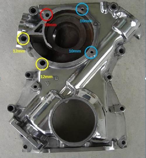
-
I discovered the SAE thread anomaly, too. I can't remember what I used as the puller cross-piece (maybe my generic steering wheel puller), but my recollection is that it really didn't take much force to make the harmonic balancer free up. I'm pretty sure I just used hardware-store grade bolts. Why not give it a try before you get too worked up about trying to find high-strength bolts? The balancer is a tight sliding fit, but not an interference fit... ... unless there's been corrosion at work.
-
PM me and I'll send you contact details for the specialist I hired. He caters to dealer service department jobs and is extremely competent. Golden Horseshoe coverage. Price is reasonable for job-done-right.
-
Good summary of Z buyer mentalities. Nissan put a lot of improvements into the 280Z's design, delivering a car that was a lot better daily driver than the original 240Z... and that was what was needed to hit the target market of the day. Unfortunately, those improvements don't really matter to buyers of a 40-year-old 'classic car'.
-
I believe this is probably related to rear-end collision protection (and maybe also protection from electrical sparks). It might also have to do with protection from shifting cargo in the hatch area. Or all of the above. Safety considerations were pretty thin when the original S30 design was laid down in the mid/late 60's. They ratcheted up significantly throughout the 70's. Consider: A tank sitting behind the rear wheels that's filled with fuel vapors, connected to the fuel tank by cloth-covered rubber hoses. Did any other cars of the era use this particular placement for the vapor recovery tank? For possible clues re manufacturer's motivation, see: Ford Pinto.
-
These dampers get added when a manufacturer discovers an unwanted truth about their drivetrain after it's too late to come up with a more elegant solution. And you know how car companies hate adding invisible items to a vehicle that don't add to the profit margin, so there has to be a substantial problem before they'll add something like this. When I worked with a manufacturer (who shall remain nameless) on the public launch of one of their prestige-class models ten years ago, I found a very similar device attached to the rear diff casing on the versions with the optional AWD powertrain. And this was well into the era of CAE, FEA and computer-driven lab-baseddrivetrain testing. I expect that the usual issue is a buzz or drone at a key highway cruising speed. An 'enthusiast' owner, of course, may never notice the issue.
-
Try Vintage Connections (west coast) and Eastern Beaver (east coast, IIRC). They'll be your best bets (esp. Eastern Beaver, who sources from Japan). Otherwise: If you need to be original-equipment: There are dozens, if not hundreds, of rusted out Z hulks that are waiting to be your parts donor. If you don't need to be OE: Either Motorsports Auto or Z-Car Depot (maybe both) has a headlight connector kit available and is waiting to receive your order.
-
Why don't you just go to Z-Car Parts of Arizona for these? They're quality parts vendor and basically located in your backyard.
-
I bought pair from a vendor called DatsunLandSoCal several years ago. They install with metal clips (from the underside, so not visible) rather than staples and I am very satisfied with the shape and dimensions, the appearance and the installation system. They sold at the time for over $50 for the pair, so not cheap. Unfortunately, the seller seems to no longer be in business. Somewhere out there, there might be a roll of this rubber, waiting to be put to use. Where is it?
-
Here's a picture of that tool, copied from 240260280's rebuild write-up on the old AtlanticZ website. A pragmatic solution (and environmentally sustainable, too!)

-
I was reading this thread out of idle interest and decided to check out Jim's recommendationre the EZ-Clip hose fittings. Look's like a great solution for aftermarket AC installers. Check out this Eaton Corp. video for details... http://www.eaton.com/Eaton/ProductsServices/Hydraulics/HoseHoseFittings/TransportationHoseProducts/ACRefrigeration/ezclip/index.htm
-
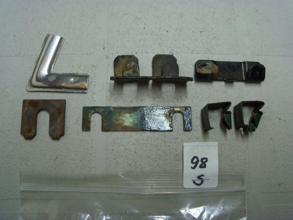
Among all of the assorted little bits of hardware that I've accumulated over the years is a 'slotted' shim plate (lower row, centre, in the photo below). I could never figure out what it was intended for... until now! If you find that you need something like this, it shouldn't be that difficult to to make up a pair from some sheet stock. Maybe make two or three pairs, so that you can stack them. If you go with metal, rust will be an issue so brass would be best (if you can find it this thick). It might be easier and better, though, if you make them from 1/32" or 1/16" clear plastic sheet stock. A little more fragile for installation, but easier to fabricate and zero rust issues. A quick cruise of your local hardware store's shelves should turn up lots of items that could be used as material donors.
-
If the locating pin on the old control arm was bent, you may want to check for frame damage back there too. Look for a wrinkled wall on one of the reinforcement 'ribs'. At some point in its life, the car may have slid off the road and smacked a curb with the rear wheel (easy to do in the snow). Probably a separate incident from whatever caused the frame twist up at the front. Hopefully, it just bent the LCA pin. Maybe somebody else who's seen similar LCA damage like this can comment.
-
Here you go...
-
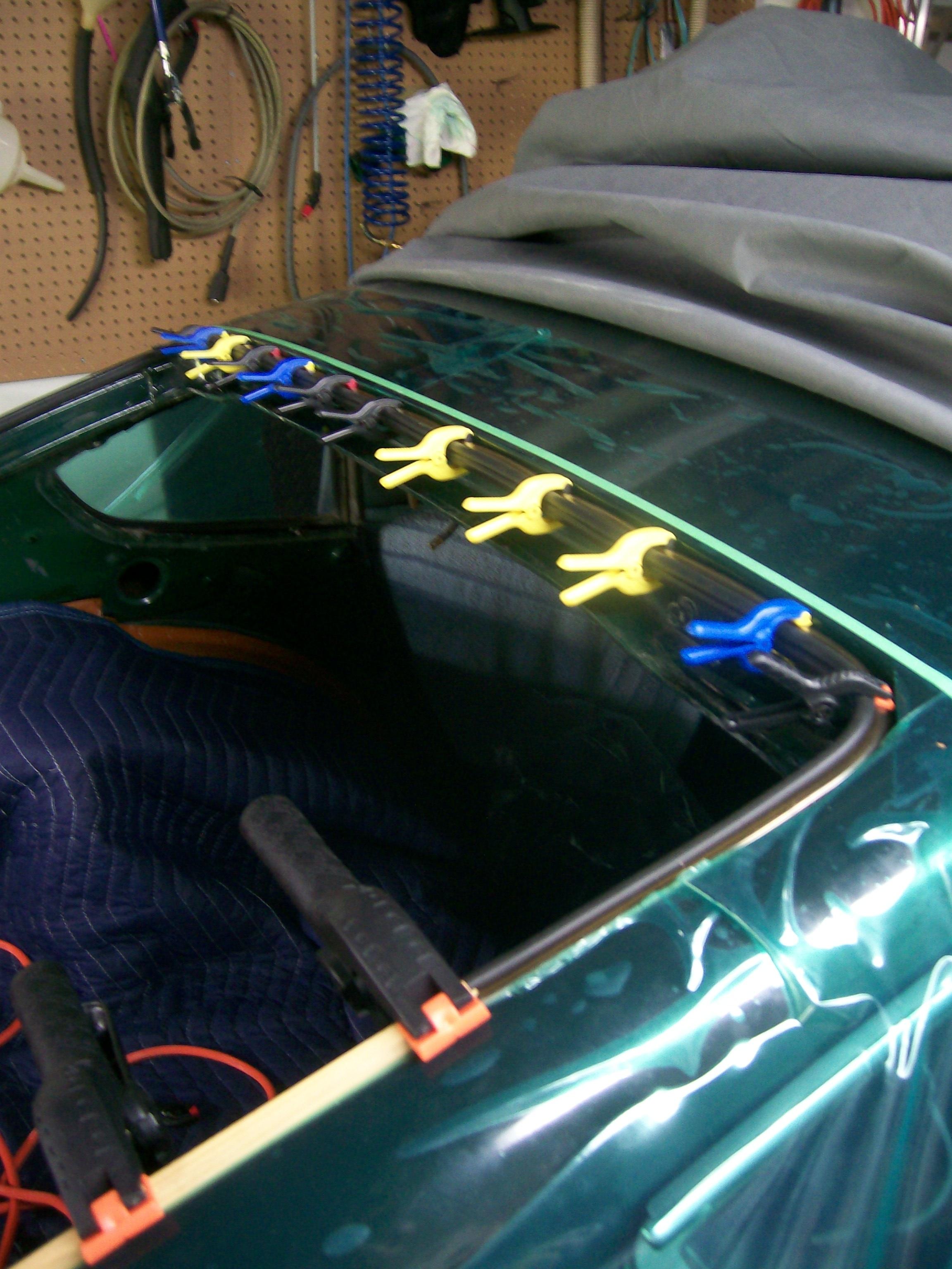
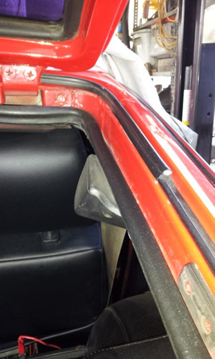
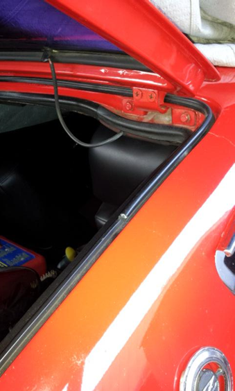
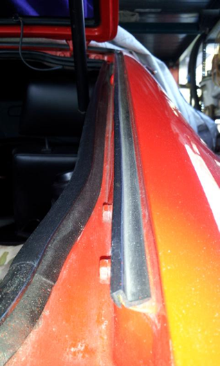
Not sure why you've had problems, 'breaking these when I close the hatch'. Maybe you can explain where the problem is occurring. Pix #1-3, below, were posted by another CZCC member (sorry, no name to credit) and show the OE-style, 3-piece outer seal. It uses a bulb-type seal across the top and around the upper corners. After that, the bottom pieces on the left and right are -- as Jim says -- really just water gutters, rather than seals. The aftermarket, one-piece seal uses a bulb design along its entire length In my experience, the top piece was difficult to install properly with the hatch in place. Also, the metal lip on which this seal mounts isn't that deep, so you shouldn't really rely on just a mechanical fit to hold the seal in place. Some judicious use of weatherstrip cement is called for here (see photo #4). If you've just been pushing the seal into place and hoping for the best, that may be the source of your problems.

-
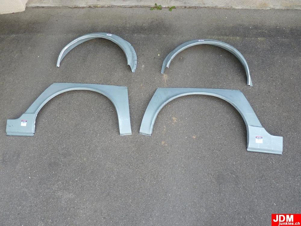
This photo may help you understand the details for the Tabco rear-quarter patch panels. Unfortunately, it doesn't answer your specific question, because the door jamb edge can't be seen on either panel. Looks like they may be difficult to integrate properly unless you also replace the outer wheel housings (also shown in the photo) so as to get a decent bonding/sealing surface around the lip. The four pieces will probably cost Cdn $800 - $1000 after you've paid for shipping, tax, duties, etc.
-
Maybe time to add one of those induction heater thingies to your tool box?
-
I think the chemical engineers designed that old brake fluid in keeping with the idea of owners trading in their vehicles every four years or so. How many people do you know who actually ponied up the money for a brake system flush? Oil and filter replacement? Absolutely. Maybe even a can of STP or top-cylinder lube. Ignition system tune-up kit? Of course. New brake pads? OK, if I really have to. But new brake fluid? I think not.
-
Not sure what you are including when you say, 'wiper linkages', so just in case: The main cause of slow wipers isn't the linkage joints. Instead, it's dried-out bushings for two stub spindles that the wiper arms are mounted to. The grease used by the factory for these bushings seems to coagulate over time and ends up performing like 'anti-grease'. Some owners have claimed that cleaning and re-greasing these bushings makes it unnecessary to upgrade the motor. I'm not sure I'd go quite that far, but it does make a big difference.
-
Given the traditional reluctance of (mainstream) auto manufacturers to spend money on parts not vital for a functioning and legal-for-sale vehicle, it's interesting that someone within the Z's product design/engineering team was able to recommend and get approval for these competition-use-only attachment points to be installed in every one of the tens of thousands of cars that were going to be produced. That's eight (maybe twelve?) captive nuts, individually tack-welded in place.
-
I was instantly a fan of anyone who could do those kind of repairs and mods while lying underneath a jacked-up car parked outdoors on on a crushed-rock driveway. None of that 3-bay-garage, epoxy-coated floor stuff for our Mr. Blue. Always made me wonder, though: Aren't there any mosquitoes or blackflies in Nova Scotia?
-
As the star of most of your well-known how-to write-ups on the Atlantic Z website, I think it would be fair to call this particular Z, 'iconic'. Kind of sad to see the exterior rust that's set in. Just patina, right?
-
The plugs are conveniently available (in various colors) from any of the leading suppliers of Z replacement/accessory parts. Try any of these: Motorsport Auto (Los Angeles) Z Car Source of Arizona Z Car Depot (St. Louis) Banzai Motorsport (Virginia) BTW, the plugs don't have to be broken to remove them. Just push the center pin all the way through (can't be extracted - sorry), then use a forked trim-removal tool to lever out the plug. The center pins typically fall down into deep recesses in the body cavities. If you rig up a length of 1" rubber hose on the end of your shopvac hose, you can probably recover most of them. A plug without the center pin is useless. Brand-new plugs and pins are easier, of course. Depends on how frugal you are. Be careful not to flex the plastic panels too much when your re-and-re-ing them (especially the one that covers the antenna location). They're a lot more expensive to replace than the plugs. Note, too, that the panels don't react well to overzealous use of heat gun to make them flex better. A blow drier is a better bet.
-
Here in my part of Canada, we are fortunate to have access to Rick Scott, parts dept manager at Brantford Nissan (Brantford, Ontario is a small city located about 60 miles west of Toronto). Rick is a long-time Z owner, restorer and enthusiast who knows the cars, the parts, the company, and the customers. He and the dealership make their lot and service area available for a Z-parts swap meet once a year. By contrast, my local Nissan dealership couldn't care less.
-
Grannyknot did some comparable fab work when he modified the front crossmember on his 240 to provide clearance for the sump of the BMW he was installing. Maybe he can post a sketch of how he'd go about fabbing this part. Great reference pix posted by 240260280. Notice the doubler plate that's installed in the region right next to the shock tower.