


Zed Head
Free Member
-
Joined
-
Last visited
Everything posted by Zed Head
-
 I apologize, I am way off my game. Getting lazy. I posted a drawing of the EFI relay. I'll see if I can find one of the ignition relay.
 -
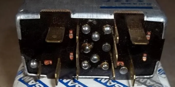
Different relay, borrowed picture from zcar forum but you can see the numbers.
-
I think that the numbers might be faintly visible on the relay, by each pin.
-
Here's a place I go to to see what parts might be correct. Found a 75 there, with EGR. Like yours. No AC though so the AC vacuum ports are blocked. https://bringatrailer.com/listing/1975-datsun-280z-43/
-
Did 1975 California have EGR? Maybe that is a 1975 intake manifold. Just checked 1976 and CA did have EGR. So 75 probably did too. I jumped the gun on the manifold I think. All I'm really certain of at this point is that 1975 never had an N47 head. They did not exist then. I'm going to go with everything is stock except the head and that it's a Maxima N47 head. Which means the head has been off. Maybe other work has been done also. Thanks for the new puzzle.
-
Pretty sure the ZX cooling fans are turned on by a switch in the thermostat housing. I had a spare ZX engine and messed around with the switch once when I was trying to make my own cooling fan system. I see some other odd things in the pictures. It has the original three piece fuel rail. But it's been messed with, screws are missing. Why not use the ZX or Maxima fuel rail? It's one piece. The AFM number might be important. If the PO used the ZX AFM there might be problems. I'd get all the numbers together and see what's what before getting carried away. I'm not even positive that that's a ZX intake manifold. Maybe it's an L24E unit.
-
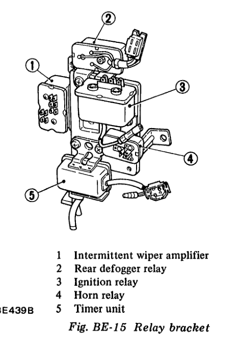
Look by the fusebox and you should recognize the relays.
-
It could be. That picture I posted in #17 is the one that came from my car. It was bypassed with a wire. Not sure what else did not work before I replaced it. It's not too hard to get to. Unplug it, remove the screws, and pull it out. If you're good with a meter you could do some testing. Post #19. Easy to open also, just bend the tabs back.
-
The built in tool and parts shelf.
-
I've thought that only the L24E Maxima N47 came with the cylinder head temperature sensor. Cylinder pressures will be a clue. Especially if it's an F54 block with flat tops.
-
Oops. Still, check the hoses. My fuel injector hoses were also age cracked and ended up shooting tiny streams of gasoline. Made it all the way to the sidewalk when I opened the hood. Another lucky break, I smelled it in the city before I got on the highway. You have a bunch of small odds and ends in front of you. Have fun.
-
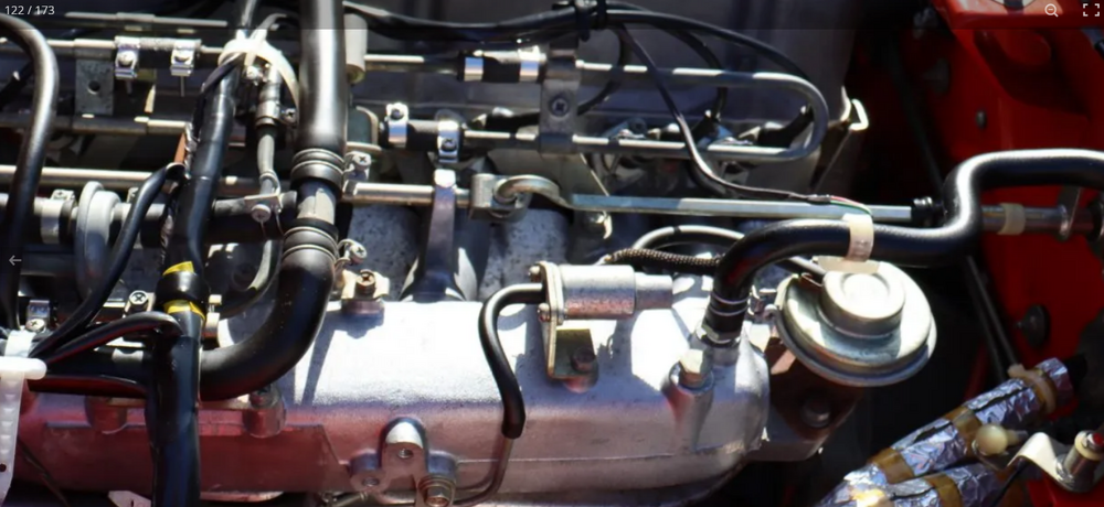
That would be the cylinder head temperature sensor. That deepens the mystery. It was used in 1980 on the P79 and P90 heads but I don't think the Z car N47 heads got it. That might be a Maxima N47 head. A popular compression ratio "upgrade" for the L28's. @madkaw knows. If you look on the driver's side by the engine mount you might be able to see the block casting number. It should be N42 or F54. I was going to mention the fuel hoses. Make sure that they are all high pressure EFI hose. I'm pretty sure that that glass filter is not rated for 36 psi. Check the rubber hose in the back from the fuel pump also. My car had low pressure hose when I got it and it split while I was driving. Luckily a UPS drive saw the fuel spilling and flagged me down.
-
It's not a big deal. It will only affect things like intake/exhaust manifold gaskets. Look between the 1 and 2 spark plugs on the cylinder head and you''ll probably see N47 or P79. Check for numbers on the exhaust manifold. They might have used the N42 manifold from the 75. The port shapes are different.
-
Somebody put a 280ZX engine in that car. Maybe they did the 5 speed too. That would be nice. The intake manifold and the cooling fan ducts over the valve cover are the tell. It should run just like the original 75 L28. Had second thoughts. Probably not. Looks like a 75 manifold. https://bringatrailer.com/listing/1975-datsun-280z-43/
-
It already has front wheel discs. Download the FSM, and wiring diagram, and Owners Manual before you get too far along. And get a multimeter, it will help a lot with the EFI system. https://www.classiczcars.com/files/ There's also a thread on the forum somewhere about things to do before trying to resurrect an old Z that's been sitting. You can avoid some damage and increase the odds of a good startup. I'd read up on that before even trying to turn the engine over. Welcome to the Z world.
-
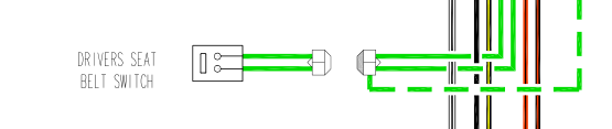
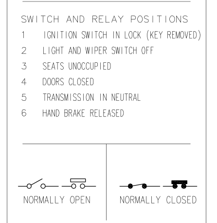
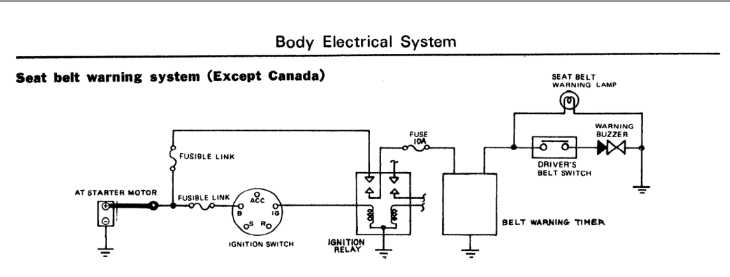
EuroDat added a dotted green line from the inhibitor switch to the seat belt switch. Maybe he had the same thoughts. Maybe the dotted line means maybe. It's not shown in the FSM original. He also changed the closed relay to open. Normally closed seems to make more sense since it would complete the buzzer circuit unitl you opened it by fastening the seat belt. Maybe. Oh well, just another puzzle that Nissan left us.

-
Or a short to ground. Not as obvious though. At about 2:00.
-
The coil and ballast resistor won't affect just a single cylinder. They will affect all of them equally. If you have a single cylinder problem it won't be fixed with a new coil and resistor.
-
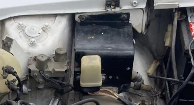
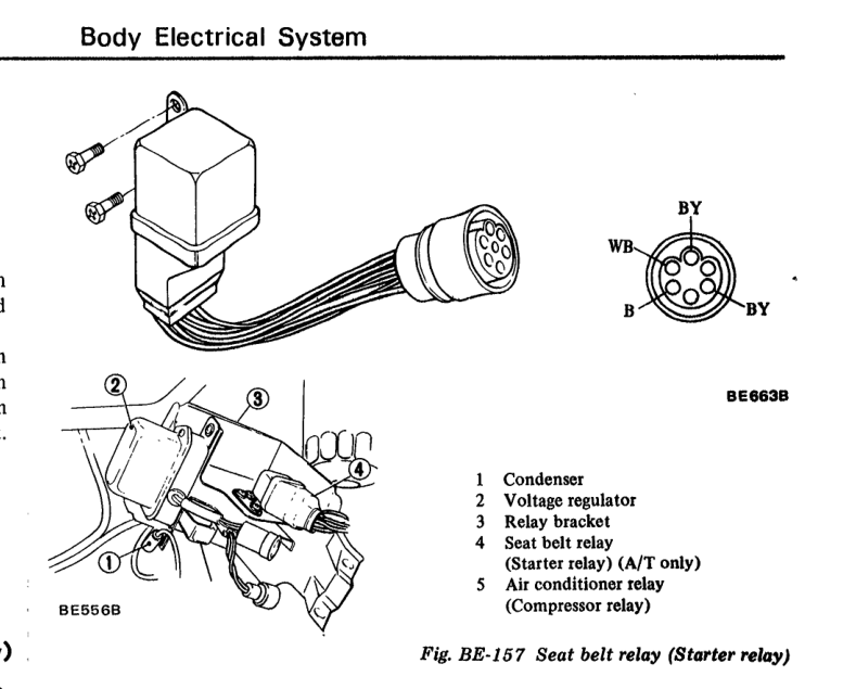
One is under the voltage regulator in the engine bay (I think that they're trying to show the oil filter in the background in their drawing ,with the bracket unbolted so that it can be reached), the other is by the fuse box in the cabin.
-
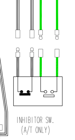
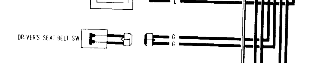
But they do show the belt switch wires as two green wires, which correlate with the two greens at the inhibitor switch. So, if the buzzer works then stops then the inhibitor is probably getting its power too. Your problem is probably in the ignition relay or the starter seat belt relay, if jumping the inhibitor doesn't work.
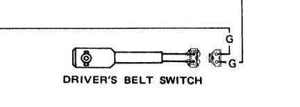
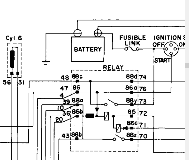
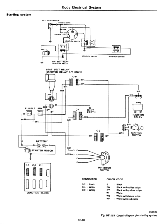
 I don't know why Nissan calls that relay a Seat Belt relay. Hard to tell by the wiring diagrams. Looks like the seat belt buzzer has its own circuit. They show the "driver's belt switch" here but not in the starting diagrams above. Confusing.
 Something that the electrical guys might be able to explain - does this diagram not show power from a fusible link passing through two normally closed relays to a realu coil then to ground? Can't be right, right?
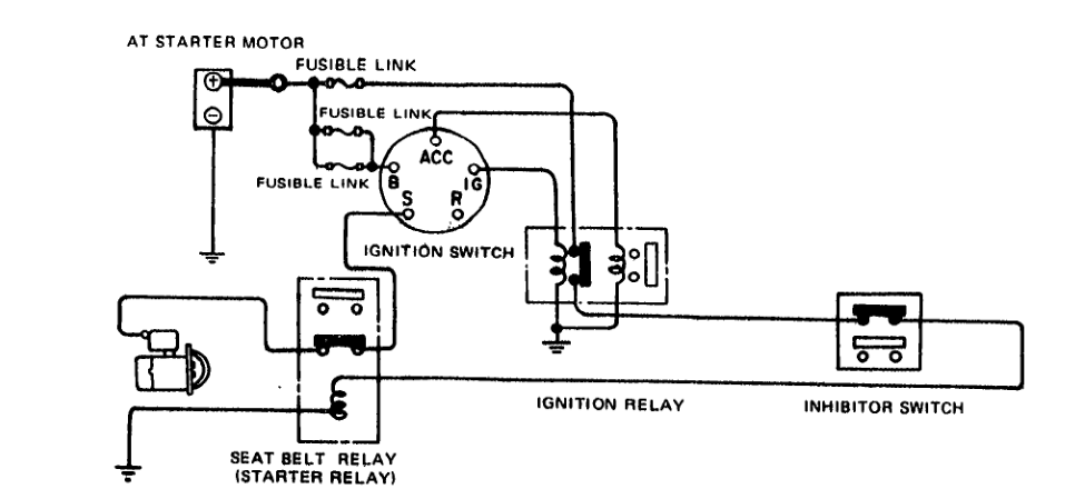


Important Information
By using this site, you agree to our Privacy Policy and Guidelines. We have placed cookies on your device to help make this website better. You can adjust your cookie settings, otherwise we'll assume you're okay to continue.